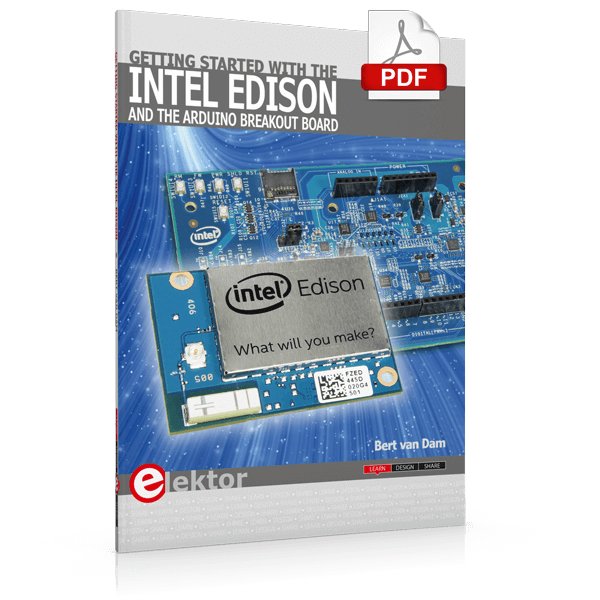
The Internet of Things is rapidly gaining interest, and that has fueled the development of the Edison. A tiny computer, the size of a postage stamp, with a lot of power and built-in wireless communication capabilities.
In this eBook we will help you get up-to-speed with the Edison, by installing the software both on the Edison as well as on your Windows PC. We will use the Edison Arduino break-out board because it is easy to work with. We will discuss Linux, Arduino C++ and Python, and show examples of how the Edison can interface with other hardware. We will use Wi-Fi and Bluetooth to set up wireless connections, and show you a trick to program sketches over Wi-Fi.
Once you have completed this book your Edison will be up and running with the latest software version, and you will have sufficient knowledge of both hardware and software to start making your own applications. You will even be able to program the Edison over USB and wireless both in Arduino C++ and Python.
This is not a projects eBook, but a toolbox that will allow you to explore the wonderful world of the Intel Edison!
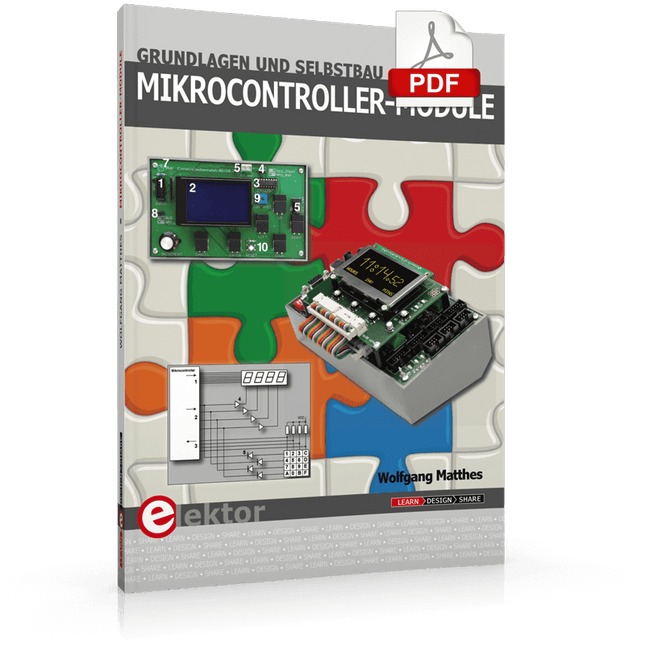
Grundlagen und Selbstbau
Weshalb nicht damit beginnen, Mikrocontroller-Module selbst zu entwickeln, zumindest aber sich in Gedanken mit solchen Aufgaben zu beschäftigen? Wie Mikrocontroller-Module aufgebaut sind und wozu sie verwendet werden, soll in 'Mikrocontroller-Module – Grundlagen und Selbstbau' dargestellt werden.
Das vorliegende Buch beleuchtet Mikrocontroller-Module, die vor allem zum Experimentieren, zum Lernen und zum Einarbeiten in die Entwicklung und Programmierung von Embedded Systems gedacht sind.
Die Entwurfsgrundsätze, Lösungsvorschläge und Projekte, die in diesem Buch beschrieben werden, sind aus zwei Ideen hervorgegangen: Erstens können neue Entwicklungen zwischen den weit verbreiteten kostengünstigen Mikrocontroller-Modulen und der industriellen Computer- und Steuerungstechnik ihren Platz finden und zweitens ist es eine Herausforderung an sich, solche Module zu entwickeln und einzusetzen.
In den ersten sieben Kapiteln dieses Buches werden die technischen Grundlagen diskutiert und anhand eigener Entwicklungen veranschaulicht. Das achte Kapitel gibt einen Überblick über diesen Modulbaukasten.
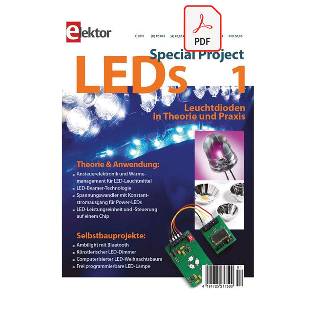
Alle Fotos aus dem Buch können hier vierfarbig heruntergeladen werden.
Inhalt
Theorie & Anwendung
Es werde Licht – Physikalische Grundlagen zu Licht und Beleuchtung
Illuminati – Beleuchtungstechnik: Grundlagen und Anwendungen
Steuerzentrale – LED-Leistungseinheit und -Steuerung auf einem Chip
LED-Beamer-Technologie – Funktionsweise und Anwendungen
Hitzeschild – Kaltleiter als Strombegrenzer für LEDs
Strahler 09 – Ansteuerelektronik und Wärmemanagement für Leuchtmittel auf LED-Basis
LEDs für eine neue Ära in der Lichttechnik – Die Leuchtdiode und ihre Möglichkeiten aus Sicht eines Herstellers
Ökobilanz von LED-Lampen – Ergebnisse einer Gesamtlebenszyklusanalyse für LED-Lampen
Lichtpumpe – Spannungswandler mit Konstantstromausgang für 0,5-W- und 1-W-Power-LEDs
LED the sun shine – LED-Licht fürs Automobil
Licht im Tunnel – Die XLamp LED-Serie von Cree
Selbstbauprojekte
Ambilight mit Bluetooth – Ein modulares RGB-Power-LED-System mit PC-Schnittstelle
Universelle LED-Lampe – Mit programmierbarem Farbwechsel
LED-Tester – Lichtstärke prüfen und vergleichen
Künstlerischer LED-Dimmer – Farbmischung stufenlos einstellen
Computerisierter LED-Weihnachtsbaum
LED-Würfel – Mogeln unmöglich!
Der Stativadapter ist individuell aus einem massiven Aluminiumblock gefertigt und bietet zwei Standard-Stativbefestigungspunkte mit 3/8-16- bzw. leichtem 1/4-20-Gewinde. Dadurch können Sie den AxiDraw bei Bedarf auf einem Stativ montieren.
Wir empfehlen dringend die Verwendung eines stabilen Stativs mit einem 3/8-16-Anschlusspunkt und einem geeigneten Gegengewicht (Sandsack, Hebegewichte usw.), um das Gewicht des AxiDraw während des Gebrauchs auszugleichen.
Die Installation ist unkompliziert und erfordert keine anderen Werkzeuge als die im Lieferumfang von AxiDraw enthaltenen: Entfernen Sie die vorhandenen Fußpolster vom AxiDraw (entweder Standard- oder Auslegerfüße, je nach Modell) und befestigen Sie diese Platte an den festgehaltenen Muttern in der Unterseite des AxiDraw. Bei AxiDraw SE/A3 (April 2019 und neuer) wird der Stativadapter direkt an den Gewindelöchern in der Basis der Maschine befestigt. Dieser robuste Stativadapter ist mit AxiDraw V3, AxiDraw V3/A3 und AxiDraw V3 XLX kompatibel. Es ist auch mit AxiDraw SE/A3 kompatibel, das im April 2019 und neuer hergestellt wurde.
Spezifikationen
Material: Eloxiertes 6061-T6-Aluminium
Größe: 3,90 x 2,36 x 0,35 Zoll (99,1 x 60 x 8,3 mm)
Gewicht: ca. 144 g
Montagematerial: im Lieferumfang enthalten (vier M4x10-Montageschrauben aus hochfestem Stahl)
Zusätzliche Staffeleibretter für AxiDraw V3/A3 können als Ersatz oder zur Bereitstellung zusätzlicher Werkstücke für den schnellen Wechsel zum nächsten Plot verwendet werden.
Dieses Set besteht aus einer 11,75 x 17 Zoll (29,85 x 43,18 cm) großen Hartfaserplatte mit angebrachten Gummifüßen sowie acht Mikrobinderklammern.
The tinySA Ultra+ ZS-407 is a compact, handheld spectrum analyzer and signal generator. Covering 100 kHz to 7.3 GHz in Ultra mode, it lets you visualize and analyze RF signals from HF right through many modern wireless bands – and can even spot signals up to ~12 GHz thanks to harmonic tracking.
The intuitive 4-inch resistive touchscreen and rechargeable battery make it great for fieldwork, while features like a built-in signal generator, switchable bandpass filters, step attenuator, USB-PC control and auto-calibration add serious versatility.
Features
Screen size: 4 inch (480 x 320)
Spectrum Analyzer for 0.1-900 MHz or, with Ultra mode enabled up to 7.3 GHz, level calibrated up to 7.3 GHz. Can observe signals up to 12 GHz
Signal Generator with sine wave output between 0.1-900 MHz or square wave up to 6.3 GHz or RF test signal output up to 7.3 GHz when not used as Spectrum Analyzer.
Switchable resolution bandpass filters from 200 Hz to 850 kHz
Built-in 20 dB optional LNA
Color display showing max 450 points providing gapless covering up to the full frequency range.
MicroSD card slot for storing measurements, settings and screen captures.
Technische Daten (Spektrum-Analyzer)
Input frequency range from 100 kHz to 900 MHz in normal mode and up to 7.3 GHz with ULTRA mode enabled
Input impedance 50 ohm when input attenuation set to 10 dB or more.
Selectable manual and automatic input attenuation between 0 dB and 31 dB in 1 dB steps when LNA not active
Maximum +/-5V DC input
Absolute maximum input level of +6 dBm with 0 dB internal attenuation
Absolute maximum short term peak input power of +20 dBm with 30 dB internal attenuation
Suggested maximum input power of +0 dBm with internal attenuation in automatic mode
For best measurements keep input power below -25 dBm
Input Intercept Point of third order modulation products (IIP3) of +15 dBm with 0 dB internal attenuation
1 dB compression point at -1 dBm with 0 dB internal attenuation
Power detector resolution of 0.5 dB and linearity versus frequency of ±2 dB below 5.3 GHz, ±5dB between 5.3 GHz and 6 GHz
Minimum burst length for correct level measurement at 850 kHz RBW in zero span mode of 50 microseconds
Absolute power level accuracy after power level calibration of ±2 dB
Built-in optional 20 dB LNA with Noise Figure of 5 dB up to 6 GHz
Lowest discernible signal without LNA at 30 MHz using a resolution bandwidth of 30 kHz of -102 dBm
Lowest discernible signal with LNA at 30 MHz using a resolution bandwidth of 200 Hz of -145 dBm
Frequency accuracy equal to the selected resolution bandwidth
Phase noise at 30 MHz of -108 dB/Hz at 100 kHz offset and -115 dB/Hz at 1MHz offset
Spur free dynamic range when using a 30 kHz resolution bandwidth of 70 dB
Resolution filters with a width of 0.2, 1, 3, 10, 30, 100, 300, 600 and 850 kHz
On screen resolution of 51, 101, 145, 290 or 450 measurement points.
Scanning speed of over 1000 points/second using largest resolution filters.
Automatic optimization of actual scanning points to ensure coverage of the whole scan range regardless of the chosen resolution bandwidth
Spur suppression option for assessing if certain signals are internally generated or actually present in the input signal
Headphone output for listening to the demodulated audio (AM only). Stereo connector with or without microphone, high impedance is louder, short protected
Technische Daten (Signalgenerator)
Sine wave output with harmonics below -40 dB of fundamental from 100 kHz to 900 MHz
Output level selectable in 1 dB steps between -115 dBm and -19 dBm
Above 800 MHz choice of two output modes:
Cleanest signal mode: square wave, up to 6 GHz with coarse frequency steps and less accurate output level
Highest accuracy mode: reduced harmonics with possibly strong spurs up to 7.3 GHz with frequency resolution equal to below 800 MHz and fine output level steps
Level accuracy ±2 dB up to 800 MHz between -72 dBm and -19 dBm, less accuracy below -72 dBm, even less accuracy below -110 dBm
Output frequency resolution 57.2 Hz
Optional AM or FM modulation frequencies between 50 Hz and 5 kHz (AM) or 1 kHz (FM) or sweep over selectable frequency span
AM modulation depth between 10% and 100%
FM deviation between 1 kHz and 300 kHz
Optional output level sweep over maximum the entire output level range
Lieferumfang
1x tinySA Ultra+ ZS407 Spectrum Analyzer
2x SMA connection cables
1x Barrel connector
1x Antenna with SMA connector
1x USB-C cable
1x microSD card (32 GB)
Downloads
Wiki
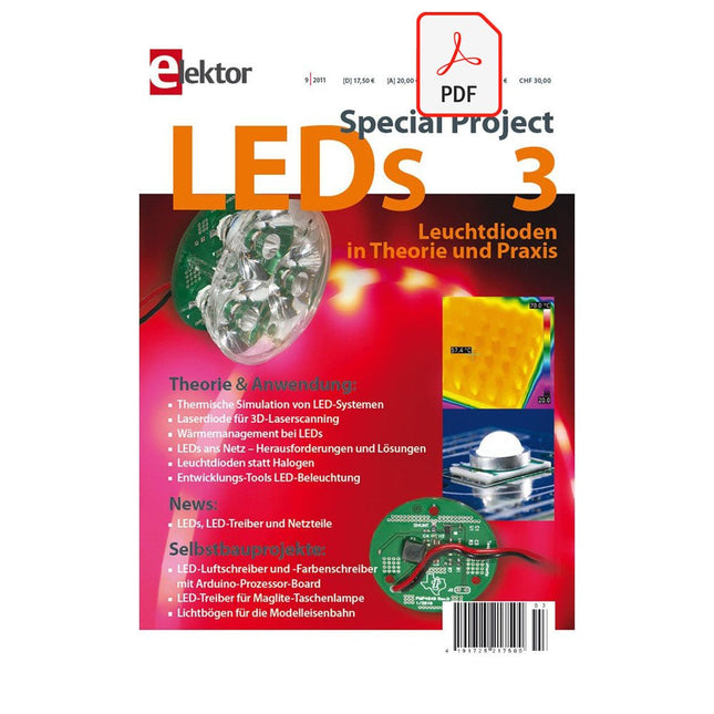
Inhalt
Theorie & Anwendung
Thermische Simulation von LED-Systemen
LUVLED
100 LEDs
LEDs ans Netz
Laserstrukturierung von TCOs
Ha(l)lo LED
Wärmemanagement bei LEDs
3D-Laserscanning mit Linienlaser und Smart Camera
Selbstbauprojekte
Lichtbögen für die Modelleisenbahn
LED-Anwendungen mit Arduino
LED-Treiber für Maglite-Taschenlampe
35 Projects for Beginners
This book is for hobbyists, students and engineers who want to learn C and how to use an mbed ARM microcontroller in an easy and fun way, without the need for cumbersome software installations.
ARM mbed microcontroller NXP LPC1768
The projects in this book are meant for beginners in C and ARM microcontrollers. That doesn't mean the projects are simple, but it does mean that they are easy to understand. We use for example USB communications, a subject that is made so easy by the mbed that it is suitable for a beginners book.
Cloud technology
The mbed NXP LPC1768 uses cloud technology, a revolutionary concept in software development. This means you do not need to install software on your PC in order to program the mbed!
The only thing you need is a browser such as Microsoft Internet Explorer, and a USB port on your PC. You can get access to your project from any PC anywhere in the world and continue working on it. When you are done a few simple mouse clicks transfer the program to your mbed hardware. Of course you can optionally download the projects and store them on your own PC.
Features of this Book
Learn how to program an mbed ARM microcontroller using cloud technology. No complicated software installation on your PC needed.
Learn programming in C by doing fun and interesting projects. No previous experience or knowledge required.
Examples of projects in this book: flashing light, timer, light activated switch, digital thermometer, people detector, USB communication, talking microcontroller, debugging, sound switch, and much more - 35 projects in total.
Examples of C subjects in this book: variables, commands, functions, program execution, pointers (introduction).
Benutzeroberfläche mit doppelter Hintergrundbeleuchtung: Die doppelt beleuchtete Taste ist genau wie die einzelne hintergrundbeleuchtete Taste, macht aber doppelt so viel Spaß! Verwenden Sie diese Komponente, wenn Sie etwas nach oben und unten oder von rechts nach links bewegen müssen. Mit ausgeschnittenem Vinyl können Sie Symbole und Aufkleber auf Stoff erstellen, die Ihren Benutzern die Tastenfunktion zeigen.
Merkmale
Komponente: 4,6' x 6,3'
Einzelne Knopfgröße: 1' Radiuskreis
Haltbarkeit der Presse: Bis zu 10.000 Pressungen unter 5 lbf
LED-Spannung: 5V
Die einzelne Taste mit Hintergrundbeleuchtung ist ein einfacher mechanischer Schalter mit einer LED im Inneren. Wenn Sie die Taste drücken, wird der Stromkreis geschlossen und Ihr Pin auf High oder Low geschaltet. Verwenden Sie die eingebettete LED, um ein leuchtendes Stromsymbol, ein Logo oder was auch immer Ihren Vorstellungen entspricht, zu erstellen.
Merkmale
Haltbarkeit der Presse: Bis zu 10.000 Pressvorgänge unter 22,24 N (5lbf)
LED-Spannung: 5V
Komponente: 2' x 3' Einzelperson (5,08 cm x 7,62 cm)
Knopfgröße: Kreis mit 1' Radius (2,54 cm)