Produkte
-
Elektor Digital Elektor 09-10/2024 (PDF)
Diese Ausgabe steht allen GOLD- und GREEN-Mitgliedern auf der ElektorMagazine-Website zum Download bereit! Sie sind noch kein Mitglied? Hier klicken! Ein autonomer SensorknotenLoRa-Datenübertragung und Solar-Stromversorgung Elektor eXpansion Board v1.0Für ESP32-S3 und andere XIAO-Controller-Boards Modelleisenbahn mit KameraEinbau eines ESP32-CAM-Moduls Breitband-Magnetantenne für LangwelleMehrere Sender ohne Abstimmung TensorFlow Lite auf kleinen MikrocontrollernEin (sehr) einsteigerfreundlicher Blickwinkel Ein Hub für RS-422 und RS-485Verdrahten Sie Ihre Geräte wie einen Stern HF-SondeMit LED-Balkenanzeige Aller Anfang...muss nicht schwer sein: mehr Verstärkerschaltungen MultiLayer-SegmentierungEin neuer Ansatz für adressierbare LED-Streifen Open VarioOpen-Source Multifunktions-Variometer für Gleitschirmflieger Aus dem Leben gegriffenÜber die Selbstverständlichkeit der Dinge KI-gestützter WasserzählerTeil 2: Firmware-Installation, Anwendung und Montage Intelligente LandwirtschaftML-basierte Schädlingserkennung mit IoT-Vernetzung Warum Anybus CompactCom die ideale Wahl für die industrielle Embedded-Kommunikation ist Kommunikationsstandard IQRFZuverlässigkeit für verlustbehaftete drahtlose Mesh-Netzwerke mit niedriger Rate Bau eines intelligenten AgrarrobotersWelche wesentlichen technischen Überlegungen und Herausforderungen müssen Entwickler von Agrarrobotern berücksichtigen? Audio-Notchfilter mit einstellbarer FrequenzUniverselle Lösung zur Unterdrückung von Frequenzen im Audiobereich Das System LeoINAGPSNützliche Einblicke in Ihr Elektrofahrzeug Solarbetriebener LoRa-KnotenEine modulare, kompakte und vielseitige IoT-Lösung AWS für Arduino und Co.Teil 2: Daten senden mit AWS-IoT-ExpressLink Projekt 2.0Korrekturen, Updates und Leserbriefe 2024: Eine Odyssee in die KIBeschleuniger: Desktop vs. Embedded, ein Blick auf einige Optionen ESP32-ReichweitenverlängererEine einfache Antennenmodifikation
€ 11,90
-

Elektor 09-10/2025 (DE)
Diese Ausgabe steht allen GOLD- und GREEN-Mitgliedern auf der ElektorMagazine-Website zum Download bereit! Sie sind noch kein Mitglied? Hier klicken! ESP32-Audio-Transceiver-Board (Teil 2)Drahtlose Audioübertragung Induktiver AM-SenderPIO des Pico in einem Arduino-Sketch Navigieren durch drahtlose ProtokolleEin technischer Leitfaden Satellitenverfolgung mit LoRaDas TinyGS-Netzwerk: Raumfahrtdaten gelangen zur Erde 4G-kompatible SMS-FernbedienungSteuern Sie Ihr Zuhause per Telefon aus der Ferne Hochgeschwindigkeits-TastkopfHochohmige Eingänge für Signale bis 200 MHz Aus dem Leben gegriffenKafka KrakenSDREin phasenkohärenter SDR-Empfänger Geschwindigkeitstests mit dem RP2350Lohnt sich der Umstieg von Raspberry Pi Pico 1 auf Version 2? Kontaktlose E-Feld-Messungen (2)Ein Laser-Vibrometer zur Erfassung der Membranschwingungen Quarze und OszillatorenQuarzgenauigkeit durch die Kondensatorwahl verbessern Aller Anfang ...... ist gar nicht schwer: Spezielle Audio-ICs Einstieg ins Programmieren von Selbstbauprojekten SPECTRAN® V6 MobileModular konfigurierbarer Echtzeit-Spektrum-Analyzer für zuverlässige Messungen in allen Frequenzbereichen Die Zukunft der KI wird in Silizium geschmiedetEin Interview mit Anastasiia Nosova Autonomer Sensorknoten v2.0 (Systemarchitektur)Solarbetriebene Sensorplattform mit integriertem GPS, LoRaWAN und weiteren Funktionen Präzise PositionsbestimmungBluetooth Channel Sounding ausprobiert Die Zukunft der Wireless-KommunikationDie ultradünnen Festkörperbatterien von BTRY Testgetriebene Programmierung in der Firmware-Entwicklung Handy-gesteuertes ModellautoWLAN + ESP32 + Smartphone = Fernsteuerung 2025: Eine KI-OdysseeKI-Denkmodelle: die Gedankenketten-Revolution Solarladeregler mit MPP-TrackingTeil 3: Software und Inbetriebnahme Web-Streaming-Kamera mit Raspberry Pi ZeroVerwendung des ZeroTier-VPN
€ 15,90
-

Elektor Digital Elektor 09-10/2025 (PDF) DE
Diese Ausgabe steht allen GOLD- und GREEN-Mitgliedern auf der ElektorMagazine-Website zum Download bereit! Sie sind noch kein Mitglied? Hier klicken! ESP32-Audio-Transceiver-Board (Teil 2)Drahtlose Audioübertragung Induktiver AM-SenderPIO des Pico in einem Arduino-Sketch Navigieren durch drahtlose ProtokolleEin technischer Leitfaden Satellitenverfolgung mit LoRaDas TinyGS-Netzwerk: Raumfahrtdaten gelangen zur Erde 4G-kompatible SMS-FernbedienungSteuern Sie Ihr Zuhause per Telefon aus der Ferne Hochgeschwindigkeits-TastkopfHochohmige Eingänge für Signale bis 200 MHz Aus dem Leben gegriffenKafka KrakenSDREin phasenkohärenter SDR-Empfänger Geschwindigkeitstests mit dem RP2350Lohnt sich der Umstieg von Raspberry Pi Pico 1 auf Version 2? Kontaktlose E-Feld-Messungen (2)Ein Laser-Vibrometer zur Erfassung der Membranschwingungen Quarze und OszillatorenQuarzgenauigkeit durch die Kondensatorwahl verbessern Aller Anfang ...... ist gar nicht schwer: Spezielle Audio-ICs Einstieg ins Programmieren von Selbstbauprojekten SPECTRAN® V6 MobileModular konfigurierbarer Echtzeit-Spektrum-Analyzer für zuverlässige Messungen in allen Frequenzbereichen Die Zukunft der KI wird in Silizium geschmiedetEin Interview mit Anastasiia Nosova Autonomer Sensorknoten v2.0 (Systemarchitektur)Solarbetriebene Sensorplattform mit integriertem GPS, LoRaWAN und weiteren Funktionen Präzise PositionsbestimmungBluetooth Channel Sounding ausprobiert Die Zukunft der Wireless-KommunikationDie ultradünnen Festkörperbatterien von BTRY Testgetriebene Programmierung in der Firmware-Entwicklung Handy-gesteuertes ModellautoWLAN + ESP32 + Smartphone = Fernsteuerung 2025: Eine KI-OdysseeKI-Denkmodelle: die Gedankenketten-Revolution Solarladeregler mit MPP-TrackingTeil 3: Software und Inbetriebnahme Web-Streaming-Kamera mit Raspberry Pi ZeroVerwendung des ZeroTier-VPN
€ 11,90
-
Elektor Digital Elektor 11-12/2020 (PDF)
NEUES LCR-MESSGERÄT 50 HZ BIS 2 MHZAutomatische Impedanzmessbrücke misst Widerstand, Kapazität und Induktivität von Bauteilen mit einer Impedanz von 10 mΩ bis 100 MΩVOM DING-DONG-TÜRGONG ZUR IOT-TÜRGLOCKEVerbinden Sie Ihre Türklingel im Home Assistant mit ESPHome!BATTERIEMANAGEMENTWas man beim Einsatz von (Lithium-)Akkus beachten mussALLER ANFANG...muss nicht schwer sein!VON DER PIKE AUF GELERNTNeues aus der Elektor-IdeenkisteBREADBOARDANSICHTEN MIT FRITZINGDESIGN ANALOGER FILTER (TEIL 2)Aktive FilterZUTRIFF FÜR UNBEFUGTE VERBOTEN!Ein Blick ins Allerheiligste aller ElektronikerVON ENTWICKLERN FÜR ENTWICKLERTipps & Tricks, Best Practice und andere nützliche InfosREVIEW: VIERKANAL-OSZILLOSKOP RIGOL DS1054ZWEIHNACHTSWUNDERKERZEPuste sie aus!DURCHSTIMMBARER RÖHREN-SINUSGENERATORRetro ist in…OSZILLOSKOPE DER SERIE PICOSCOPE 2000REVIEW: GENERATOR RIGOL DG2072KICAD-PLUGINS UND ADD-ONSDIFFERENTIELLER STROMTASTKOPF FÜR OSZILLOSKOPE 2.0Ströme mit dem Oszilloskop messenDIE HEWLETT-PACKARD INTERFACE-LOOPVerbinde die Welt!DIE ZUKUNFT DES MASCHINELLEN LERNENSEin Interview mit Daniel SitunayakeMOBILE APPS FÜR ANDROID UND IOSAus einem Guss programmiertAUS DEM LEBEN GEGRIFFENDer Zusammenprall von Alphas, Betas und Gammas5G: WIE INFRASTRUKTUR UNSERE GESELLSCHAFT FORMTPRAKTISCHES ESP32-MULTITASKING (5)Task-EreignisbenachrichtigungLORA-GPS-TRACKERMit offener Hard- und SoftwarePROGRAMMIERUNG EINES ENDLICHEN ZUSTANDSAUTOMATENMit 8-bit-PICs in Assembler und CHEXADOKUSudoku für Elektroniker
€ 11,90
-
Elektor Digital Elektor 11-12/2021 (PDF)
NVIDIA JETSON NANO - BILDVERARBEITUNG FÜR EINSTEIGER (TEIL 2) Erkennen von Objekten mit Edge-Impulsen ELEKTOR JUMPSTARTER-NEWS Kommende Kampagnen OPEN-SOURCE-GPS-TRACKING-PLATTFORM Fahrzeug-Tracking ohne fremde Cloud mit Traccar MULTIFUNKTIONS-KOMPONENTENTESTER LCR-T7 VON JOY-IT Tests von passiven Bauteilen, diskreten Halbleitern und IR-Fernbedienungen RAUSCH-SYNTHESIZER Vom Rauschen zur Musik mit dem PRBSynth1 ALLER ANFANG … ist gar nicht schwer! Weiter geht's mit der Spule... DIE NEURONEN IN NEURONALEN NETZEN VERSTEHEN Teil 2: Logische Neuronen BLITZLICHT-GESCHÜTZTER ANALOGSPEICHER-ZUSATZ FÜR DAS MANIPULATIONSSICHERER DATENPAKET Probleme mit der Sicherheit? Bekämpfen Sie Feuer mit Feuer! LCR-METER-PLAKAT BLUETOOTH-BEACONS IN DER PRAXIS Ortsbestimmung in Innenräumen C-PROGRAMMIERUNG AUF RASPBERRY PI Ein Beispielkapitel: Kommunizieren über WLAN EMV-VORKONFORMITÄTSTEST FÜR IHR DC-VERSORGTES PROJEKT Teil 2: Die Hardware und wie man sie benutzt PARALLAX-PROPELLER 2 Teil 5: Das Innenleben des Smart Pins MODBUS ÜBER WLAN Teil 1: Hardware und Programmierung ZUTRITT FÜR UNBEFUGTE VERBOTEN Wie der Junior-Computer wieder zum Leben erweckt wurde BAUEN SIE IHREN EIGENEN HOCHPRÄZISIONSKALIBRATOR -10 V bis +10 V, 0 bis 40 mA, 0,001% ARDUINO NANO RP2040 VERBINDEN Raspberry Pi RP2040 + WLAN + Bluetooth DER PHYSISCHE KÖRPER DER KÜNSTLICHEN INTELLIGENZ PROJEKT 2.0 Korrekturen, Updates und Leserbriefe GRAFISCHE BENUTZEROBERFLÄCHEN MIT PYTHON UND GUIZERO CO2-MESSGERÄT-SET FÜRS KLASSENZIMMER Ein ESP8266-basiertes Gerät, entwickelt von der FH Aachen NOSTALGISCHES MW/LW-RADIO MIT MK484 ...macht immer Spaß beim Bauen! 60 JAHRE ELEKTOR Es werde Licht! HEXADOKUS Das Original von Elektorized Sudoku
€ 11,90
-
Elektor Digital Elektor 11-12/2022 (PDF)
Diese Ausgabe steht allen GOLD- und GREEN-Mitgliedern auf der ElektorMagazine-Website zum Download bereit! Sind Sie noch kein Mitglied? Hier klicken! High-End aus dem Elektor-Labor High-End-Verstärker Fortissimo-100 Vollsymmetrische Audio-Endstufe mit 100/190 W Frequenzbestimmung unbekannter Schwingkreise und Quarze Tipps & Tricks, Best Practices und andere nützliche Informationen Platinen entwerfen Tipps aus der Praxis Löten ….na und? Ein etwas genauerer Blick auf die heutige Löttechnik Bluetooth-Garagentorsteuerung mit niedriger Latenz Steuerung mit kurzen BLE-Nachrichten über ein Smartphone Idealer Dioden-Controller „Dioden“ mit geringer Verlustleistung LED-Girlanden mit ESP32 und FreeRTOS Blinken und variable Helligkeit Aller Anfang ... ... muss nicht schwer sein: Es geht weiter mit den Z-Dioden UKW/DAB+-Empfänger Das Beste aus beiden Welten Aus dem Leben gegriffen Electronica Obscura Software-Fehler drahtlos auf der Spur Zirkularer Puffer und Webserver auf dem ESP32 Hat Covid einen Innovationsschub im Ingenieurwesen ausgelöst? Innovative Bauteile, Komponenten und Lösungen 2022 Ersa i-CON TRACE – die IoT-Lötstation für Praktiker Infografiken Was wollen wir mit all diesen Daten machen? Ansteuerung des E-Paper-Displays von Ynvisible Immer innovativ mit InnoFaith F&A mit Walter Arkesteijn Industrielle Automatisierung Einfache und skalierbare IoT-Nachrüstungen Das Oszilloskop der nächsten Generation für schnellere Einblicke Rohde & Schwarz präsentiert die R&S MXO 4 Serie Linear-Steckverbinder mit niedrigem Profil lösen Aufgaben im Multi-Signal-Datenmanagement Smart – Innovativ – Kosteneffizient GateMate-FPGAs entwickelt und hergestellt in Deutschland Vom Layout zum Prototypen an einem Tag 4-Lagen-PCBs im Elektronik-Labor Tools für die kostengünstige Sensorentwicklung Isolierter Analogausgang für Arduino Uno Betreten für Unbefugte verboten! Herr Karenovics entdeckt das Theremin electronica fast forward 2022 - unterstützt von Elektor Line-up und Zeitplan Senderpeilung Verlorene Funk-Wettersensoren wiederfinden Das interne Rauschen eines ICs abschätzen Mit einer einfachen Methode Ethik in Aktion Unterstützt vom WEEF Ohne Ethik kein nachhaltiges Geschäft Ein Interview mit Professor Stefan Heinemann Der WEEF-Index 2023 Filter-Software Design-Tools für analoge Filter TV-B-weg! ... oder zumindest: B-OFF RP2040-basierte Luftgütemessung Kickstart zu Python 3 Ein Beispiel-Kapitel: Digitale Bildverarbeitung und Wand-Bibliothek Polysicherungen Bemerkenswerte Bauteile Hexadoku
€ 11,90
-
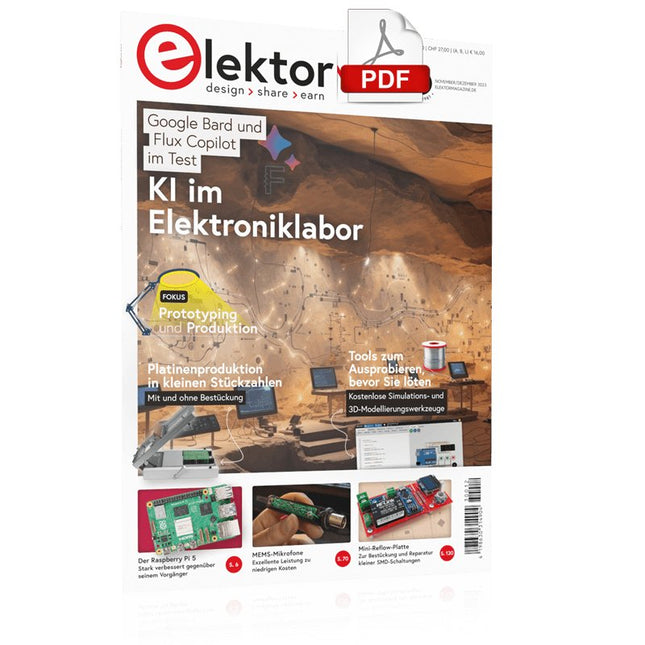
Elektor Digital Elektor 11-12/2023 (PDF)
Diese Ausgabe steht allen GOLD- und GREEN-Mitgliedern auf der ElektorMagazine-Website zum Download bereit! Sind Sie noch kein Mitglied? Hier klicken! Der Raspberry Pi 5 Gegenüber diesem Vorgänger enormer Rückstand KI im Elektroniklabor Schaltungsdesign, Bauteil-Suche, Software Funktionsgenerator mit dem Arduino Nano Nano + Code = Funktionsgenerator Solarbetriebene Weihnachtsgirlande Eine umweltfreundliche Lösung für die Dekoration Ihres Balkons USB-Killer-Detektor Besser sicher als traurig Ein einfaches CNC-Gehäuse Schritt für Schritt mit Autodesk Fusion 360 Platinenproduktion in kleinen Stückzahlen Mit und ohne Bestückung IoT-Simulation vereinfacht mit Wokwi Entwickler Uri Shaked über Entwicklung, Software und mehr Eine Anleitung zur Bare-Metal-Programmierung Teil 3: CMSIS-Header, automatische Tests und ein Webserver LoRa, ein Schweizer Taschenmesser Teil 2: Hard- und Software MEMS-Mikrofon Entwurf und Konstruktion eines Messmikrofons Werkzeuge zum Ausprobieren, bevor Sie löten Simulations- und 3D-Modellierungstools, die kostenlos genutzt werden können Neue Tools von Microchip! Version 5 von PICkit und ICD jetzt erhältlich Rapid Prototyping von flexibler, dehnbarer Elektronik Wie Voltera NOVA Innovationen bei tragbaren elektronischen Systemen beschleunigen Galvanische Trennung Fototransistor-Optokoppler erfolgreich einsetzen Die komplexe Lösung oder die Lösung von Anybus? Embedded Industrial Ethernet als Kurzstrecke statt als Marathon Ihre essentielle DFM-Checkliste Wie Sie mit dem Entwurf für die Fertigung beginnen Filamente für den 3D-Druck Arten, Eigenschaften und Verwendung im Prototyping Spezialisten für eine grundlegende Signalauswertung von ELF bis EHF-Band Aaronias neuester Echtzeit-Spektrumanalyzer der SPECTRAN® V6-Serie Herausforderungen der DFM-Analyse für Flex- und Rigid-Flex-Design Einrichten einer SMT-Fertigungsstrecke Die richtige Kombination für die zuverlässige Baugruppe Revolution in der Industrie Der Aufstieg der Autonomen Mobilen Roboter (AMR) Für höchste Anforderungen weiterentwickelt R&S MXO 5 mit acht Kanälen ergänzt Oszilloskope der nächsten Generation Aller Anfang... ... muss nicht schwer sein: Verstärkung von Unterschieden Mini-Reflow-Platte Für die Bestückung und die Reparatur kleiner SMD-Schaltungen Starte nicht mit einem Prototyp – starte mit einem Pretotyp! Prüfe zunächst, ob es einen Markt für dein Produkt gibt, bevor du deinen Lötkolben vorwärmst 2023: Odyssee in die KI Hilfe beim Entwerfen eines physikalischen Projekts erhalten Innovationen aus Brüssel Unterstützung für die Spitzentechnologie
€ 11,90
-
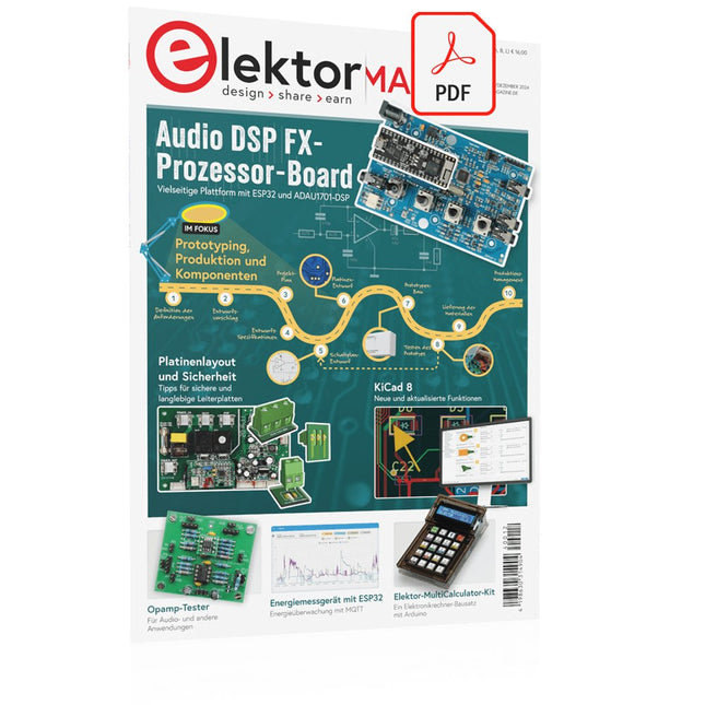
Elektor Digital Elektor 11-12/2024 (PDF)
Diese Ausgabe steht allen GOLD- und GREEN-Mitgliedern auf der ElektorMagazine-Website zum Download bereit! Sie sind noch kein Mitglied? Hier klicken! Audio-DSP-FX-Prozessor-BoardTeil 1: Eigenschaften und Design 50 Jahre Elektor in englischer Sprache KiCad 8Neue und aktualisierte Funktionen MultiCalculator-KitEin Elektronikrechner-Bausatz von Elektor mit Arduino Preiswerte GNSS-RTK-SystemeFür zentimetergenaue Positionsbestimmung Platinenlayout und SicherheitTipps für sichere und langlebige Leiterplatten Opamp-TesterFür Audio- und andere Anwendungen Projekt-Update #4 : Energiemessgerät mit ESP32Energieüberwachung mit MQTT Echtzeit-Spektrumanalyzer mit Waveguide-Technologie und Multi-Schnittstellen-PCsAaronia etabliert neues Produktsegment und präsentiert erste Prototypen auf der electronica in München electronica 2024Highspeed und robuste Board-to Board Steckverbinder InduktivitätenSpulen und Ferrite anwendungsorientiert selektieren EMI-Abschirmung zur Einhaltung der elektromagnetischen Konformität Das ultimative Werkzeug für jeden Elektronik-EnthusiastenUnendliche Möglichkeiten mit Red Pitaya und 1.000+ Click Boards™ Die 100 % durchgängige Flussmittelseele Siglent stellt seine neue Vektornetzwerkanalysator-Plattform SNA6000A vor HDI der MittelklasseEin neuer ökonomischer PCB Pooling Service für hochpolige BGAs Ferngesteuerte IoT-EntwicklungDie einzige Lösung für Fernunterricht und Entwicklung in der Embedded-Industrie Herausforderungen der DFM-Analyse für Flex- und Rigid-Flex-Design Aus dem Leben gegriffenMikrotechnophobie Feliz Natal: 3D-WeihnachtsbaumEine 3D-Platine mit preiswertem 32-Bit-Mikrocontroller Aller Anfang......muss nicht schwer sein: Weiter geht es mit den Opamps! Ein autonomer SensorknotenProjekt-Update #1: Reduzierung der Leerlauf-Stromaufnahme mit externer RTC mit Leistungsschalter 2024: Eine Odyssee in die KIEin Blick zurück in die Zukunft LED-Displays mit dem MAX7219Ein praktischer Ansatz für einen großartigen Chip Projekt 2.0Korrekturen, Updates und Leserbriefe VibroTactile-HandschuheEin Durchbruch für Parkinson-Patienten?
€ 11,90
-

Elektor 11-12/2025 (DE)
Diese Ausgabe steht allen GOLD- und GREEN-Mitgliedern auf der ElektorMagazine-Website zum Download bereit! Sie sind noch kein Mitglied? Hier klicken! Relio v1.0 – Anwesenheitserkennung und FernsteuerungEin Matter-fähiger Smart-Controller für Hausgeräte Bessere Leiterplatten entwerfenEin praxisnaher Leitfaden für Profis und Maker KiCad 9Die wichtigsten neuen und aktualisierten Funktionen Präzisions-Picoamperemeter (Teil 1)Mit Kennlinienschreiber-Funktion bis in den pA-Bereich Analoger Pipeline-VerzerrerEin cooler Audioeffekt für Gitarren und andere Instrumente Halogene in LötmittelnFakten statt Mythen 100-mV-Durchgangsprüfer Wer treibt die europäische Elektronik voran?Unternehmen im Fokus productronica 2025Neuheiten in Elektronikentwicklung und -fertigung Automatisierung bewältigt Herausforderungenwie Reshoring, Zölle und Arbeitskräftemangel Mehr als ZukunftssicherheitKreislaufwirtschaft in der Elektronik Passive BauelementeVerlustarme Induktivitäten für hocheffiziente DC/DC-Wandler PCB-Produktion im WandelDesktop-Maschinen eröffnen neue Wege für die Leiterplattenfertigung Aller Anfang ...... braucht Spannung UHD-Displays mühelos ansteuernIhr Leitfaden, um unterschiedliche TFT-LCDs schnell in Betrieb zu nehmen Löten im Jahr 2025Praktische Tipps direkt von der Werkbank Weihnachtsstern 2025Ein Stern wird gelötet SimulIDEEin All-in-One-Werkzeug für die Schaltungsentwicklung 2025: Eine KI-OdysseeVom Autovervollständiger zum Kollegen Wortreicher WeihnachtsbaumEin festliches Elektronikprojekt mit verbalem Highlight Projekt 2.0Korrekturen, Updates und Leserbriefe ESP32-Audio-Transceiver-Board (Teil 3)Stereosender und Dual Radio
€ 15,90
-

Elektor Digital Elektor 11-12/2025 (PDF) DE
Diese Ausgabe steht allen GOLD- und GREEN-Mitgliedern auf der ElektorMagazine-Website zum Download bereit! Sie sind noch kein Mitglied? Hier klicken! Relio v1.0 – Anwesenheitserkennung und FernsteuerungEin Matter-fähiger Smart-Controller für Hausgeräte Bessere Leiterplatten entwerfenEin praxisnaher Leitfaden für Profis und Maker KiCad 9Die wichtigsten neuen und aktualisierten Funktionen Präzisions-Picoamperemeter (Teil 1)Mit Kennlinienschreiber-Funktion bis in den pA-Bereich Analoger Pipeline-VerzerrerEin cooler Audioeffekt für Gitarren und andere Instrumente Halogene in LötmittelnFakten statt Mythen 100-mV-Durchgangsprüfer Wer treibt die europäische Elektronik voran?Unternehmen im Fokus productronica 2025Neuheiten in Elektronikentwicklung und -fertigung Automatisierung bewältigt Herausforderungenwie Reshoring, Zölle und Arbeitskräftemangel Mehr als ZukunftssicherheitKreislaufwirtschaft in der Elektronik Passive BauelementeVerlustarme Induktivitäten für hocheffiziente DC/DC-Wandler PCB-Produktion im WandelDesktop-Maschinen eröffnen neue Wege für die Leiterplattenfertigung Aller Anfang ...... braucht Spannung UHD-Displays mühelos ansteuernIhr Leitfaden, um unterschiedliche TFT-LCDs schnell in Betrieb zu nehmen Löten im Jahr 2025Praktische Tipps direkt von der Werkbank Weihnachtsstern 2025Ein Stern wird gelötet SimulIDEEin All-in-One-Werkzeug für die Schaltungsentwicklung 2025: Eine KI-OdysseeVom Autovervollständiger zum Kollegen Wortreicher WeihnachtsbaumEin festliches Elektronikprojekt mit verbalem Highlight Projekt 2.0Korrekturen, Updates und Leserbriefe ESP32-Audio-Transceiver-Board (Teil 3)Stereosender und Dual Radio
€ 11,90
-
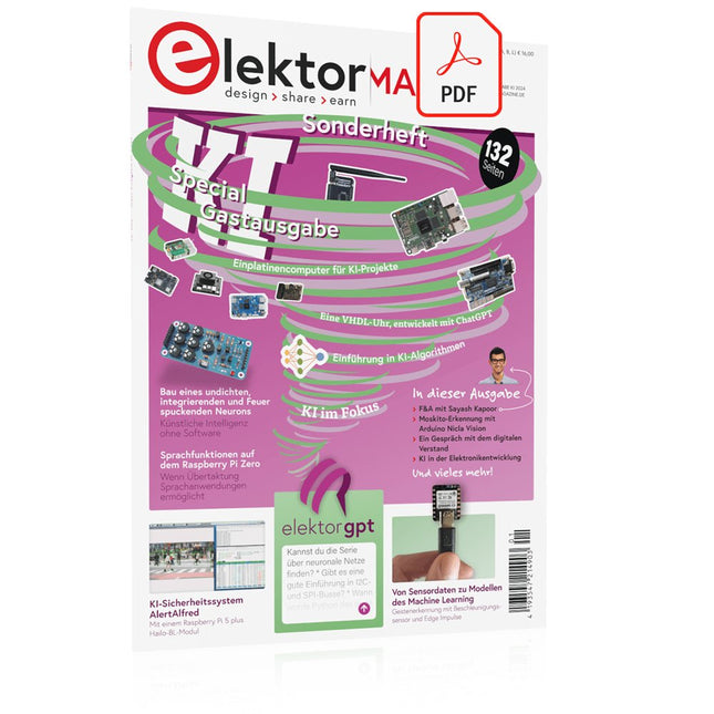
Elektor Digital Elektor AI Guest Edition 2024 (PDF)
Diese Ausgabe steht allen GOLD- und GREEN-Mitgliedern auf der ElektorMagazine-Website zum Download bereit! Sie sind noch kein Mitglied? Hier klicken! KI-Sicherheitssystem AlertAlfredMit einem Raspberry Pi 5 plus Hailo-8L-Modul KI in der ElektronikentwicklungEin Update nach nur einem Jahr Einführung in KI-AlgorithmenPrompt: Welche Algorithmen werden in KI-Tools verwendet? Einplatinencomputer für KI-ProjekteÜberblick und Hintergründiges Von Sensordaten zu Modellen des Machine LearningGestenerkennung mit einem Beschleunigungssensor und Edge Impulse Bau eines undichten, integrierenden und Feuer spuckenden NeuronsKünstliche Intelligenz ohne Software ChatGPT für den ElektronikentwurfMacht GPT-4o es besser? KI at the Edge mit dem ESP32-P4 Sprachfunktionen auf dem Raspberry Pi ZeroWenn Übertaktung Sprachanwendungen ermöglicht Die wachsende Rolle von Edge-KIEin Trend, der die Zukunft prägt Die Macht der Edge-KI entfesselnEin Gespräch mit François de Rochebouët von STMicroelectronics Eine VHDL-Uhr, entwickelt mit ChatGPT Die wahren Auswirkungen der KISayash Kapoor über „KI-Schlangenöl“ und mehr Das Neueste von BeagleBoardBeagleY-AI, BeagleV-Fire, BeagleMod, BeaglePlay und BeagleConnect Freedom Moskito-Erkennung mit offenen Daten und Arduino Nicla Vision KI heute und morgenEinblicke von Espressif, Arduino und SparkFun Zeitleiste: Künstliche Intelligenz BeagleY-AIDer neuste Einplatinencomputer für KI-Anwendungen KI im FokusPerspektiven aus der Elektor-Community Maschinelles Sehen mit OpenMVBau eines Limonadendosen-Detektors Ein Gespräch mit dem digitalen VerstandChatGPT vs. Gemini Skilling Me Softly with this Bot?Scheitert die KI-Revolution im elektronischen Bereich an mangelnder sozialer Präzision?
€ 11,90
-
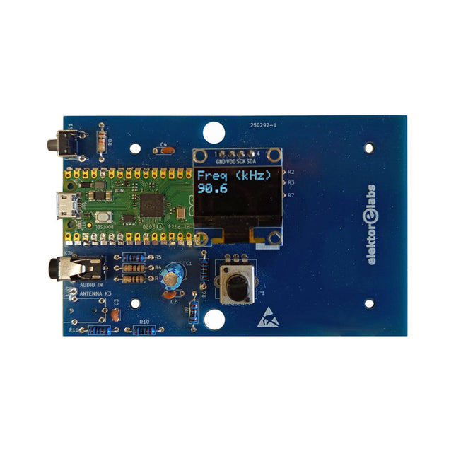
Elektor Labs Elektor AM-Sender-Kit
Bauen Sie Ihren eigenen Vintage-Radiosender Das Elektor AM-Sender-Kit ermöglicht das Streamen von Audio auf Vintage-AM-Radioempfänger. Basierend auf einem Raspberry Pi Pico Mikrocontroller-Modul kann der AM-Sender auf 32 Frequenzen im AM-Band senden, von 500 kHz bis 1,6 MHz in 32 Schritten von ca. 35 kHz. Die Frequenz wird mit einem Potentiometer gewählt und auf einem 0,96" OLED-Display angezeigt. Eine Taste ermöglicht das Umschalten des Sendemodus zwischen Ein und Aus. Die Reichweite des Senders hängt von der Antenne ab. Die integrierte Antenne bietet eine Reichweite von wenigen Zentimetern, sodass der AM-Sender nahe am Radio oder im Radio selbst platziert werden muss. Eine externe Loop-Antenne (nicht enthalten) kann angeschlossen werden, um die Reichweite zu erhöhen. Das Elektor AM-Sender-Kit wird als Bausatz geliefert, den Sie selbst auf die Platine löten müssen. Features Die Platine ist kompatibel mit einem Hammond-1593N-Gehäuse (nicht enthalten).Ein 5-VDC-Netzteil mit Micro-USB-Anschluss (z. B. ein altes Handy-Ladegerät) wird benötigt, um das Kit zu betreiben (nicht enthalten). Stromaufnahme: 100 mA. Die Arduino-Software (benötigt Earle Philhowers RP2040-Boards-Paket) für das Elektor-AM-Sender-Kit sowie weitere Informationen sind auf der Elektor-Labs-Seite dieses Projekts verfügbar. Stückliste Widerstände R1, R4 = 100 Ω R2, R3, R8 = 10 kΩ R5, R6, R9, R10, R11 = 1 kΩ R7 = optional (nicht enthalten) P1 = Potentiometer 100 kΩ, linear Kondensatoren C1 = 22 µF 16V C2, C4 = 10 nF C3 = 150 pF Sonstiges K1 = 4×1 Stiftleiste K2, K3 = 3,5-mm-Buchse Raspberry Pi Pico Drucktaste, Winkelmontage 0,96" monochromes I²C-OLED-Display Leiterplatte 150292-1
€ 34,95€ 29,95
Bestpreis
-

Elektor Classics Elektor Archiv 1970-2025 (USB-Stick)
56 Jahrgänge auf USB – Jetzt inkl. Jahrgang 2025! NEU: Für Artikel ab dem Jahr 2000 gibt es jetzt eine separate Downloadoption für Zusatzmaterialien wie PCB-Layouts, Gerber-Dateien und Software! Dieser USB-Stick (64 GB, USB 3.0) enthält alle Elektor-Ausgaben der Jahrgänge 1970 bis 2025 im PDF-Format. Die Fachzeitschrift Elektor vermittelt ihren Lesern moderne Elektronik und Computertechnik durch die Veröffentlichung nachbausicherer, professionell konzipierter Schaltungen zu allen Bereichen der Elektronik: Audio & Video Computer & Peripherie Grundlagen Haus & Hof Hobby & Modellbau Hochfrequenz Messen & Testen Mikrocontroller Stromversorgung Themen, die sich nicht katalogisieren lassen. Die über 12.000 einzelnen Elektor-Artikel sind chronologisch nach Erscheinungsdatum (Monat/Jahr) geordnet. Elektor GPT Elektor GPT ist ein KI-gestütztes Tool, das Benutzern hilft, durch das jahrzehntelange Elektor-Archiv zu navigieren. Mithilfe erweiterter Suchalgorithmen und Verarbeitung natürlicher Sprache findet Elektor GPT schnell Artikel, Projekte und andere Ressourcen aus dem Archiv. Technische Daten Speicher 64 GB Anschlüsse 1x USB-A1x USB-C Systemvoraussetzungen Rechner geeignet für Adobe Reader ab Version 7.0 Web-Browser
€ 199,95€ 99,95
Bestpreis
-

Elektor Classics Elektor Archive 1978-2025 (USB Stick) FR
48 années sur clé USB – Année 2025 incluse ! NOUVEAU : Pour les articles à partir de l’année 2000, une option de téléchargement séparée est désormais disponible pour des ressources supplémentaires telles que les plans de PCB, les fichiers Gerber et les logiciels ! Cette clé USB (64 Go, USB 3.0) contient tous les numéros d’Elektor en français des années 1978 à 2025. Elektor propose à ses lecteurs des montages électroniques de conception professionnelle et aisément reproductibles, dans les domaines de l’électronique et de l’informatique appliquées. Il leur apporte également des informations sur l’évolution technologique et les nouveaux produits. Les principaux domaines d’application sont : Alimentation Audio, vidéo & HiFi Auto, moto & vélo Domestique Expérimentation Hautes-fréquences Informations générales Loisirs Mesure Microcontrôleurs & PC Photographie Plus de 10.000 articles d’Elektor sont réunis sur cette clé USB, présentés par ordre de parution (mois/année). Elektor GPT Elektor GPT est un outil basé sur l'IA qui aide les utilisateurs à naviguer dans les archives d'Elektor, vieilles de plusieurs décennies. Grâce à des algorithmes de recherche avancés et au traitement du langage naturel, Elektor GPT trouve rapidement des articles, des projets et d'autres ressources dans les archives. Spécifications Stockage 64 Go Connecteurs 1x USB-A1x USB-C Matériel et logiciel requis Ordinateur avec Adobe Reader version 7 ou sup. Navigateur Internet
€ 199,95€ 99,95
Bestpreis
-
Elektor Digital Elektor-Special: Gastausgabe von Arduino 2022 (PDF)
Diese Ausgabe steht allen GOLD- und GREEN-Mitgliedern auf der ElektorMagazine-Website zum Download bereit! Sind Sie noch kein Mitglied? Hier klicken! Arduino Portenta Machine Control und Arduino Potenta H7 Ein CAN-zu-MQTT Gateway Demo Projekt Ausgepackt: Der Elektor-LCR-Meter-Bausatz von Elektor MicroPython hält Einzug in die Arduino-Welt Vernetzte Projekte, einfach eingerichtet Ihr Weg in die Arduino-Cloud Einführung in TinyML Groß ist nicht immer besser Arduino K-Weg Komfortableres Schreiben von Arduino-Sketches Lernen Sie Arduino kennen! Erste Schritte mit Portenta X8 Sichere Softwareverwaltung mit Containern Skalierbare, sichere Anwendungen erstellen, in Betrieb nehmen und pflegen Arduino Portenta X8 mit dem i.MX 8M Mini-Anwendungsprozessor von NXP und dem EdgeLock Secure Element SE050 Wie ich mein Haus automatisiert habe Arduino-CEO Fabio Violante entwickelt und teilt Lösungen Altair-8800-Emulator Hardware-Simulation eines alten Computers MS-DOS auf dem Portenta-H7-Board Alte Software auf moderner Hardware ausführen Bauen Sie es selbst an Eine digital gesteuerte Anzuchtbox für Indoor-Farming Kann Hausautomatisierung den Planeten retten? MQTT auf dem Arduino Nano RP2040 Connect Professionelle Anwendungen mit Arduino Pro Intelligente Backöfen der nächsten Generation Tagvance sorgt mit Arduino für sicherere Baustellen Santagostino ist da! mit einer Fernüberwachung, die KI für vorausschauende Wartung nutzt Höchste Sicherheit mit der MKR-basierten Lösung von RIoT Secure Eine neue Generation des Wassermanagements mit Open-Source Senso Abholzung mit Schallanalyse aufspüren Die Arduino-Bibliothek Mozzi für Klangsynthese Einblicke von Tim Barrass Das neue Portenta-X8-Board (mit Linux!) und Max Carrier machen es möglich! Wie Arduino Schülern hilft, zukünftige Fähigkeiten zu entwickeln Must-Haves für Ihren Elektronik-Arbeitsplatz Die Bedeutung der Robotik in der Ausbildung Ein zuverlässiges IoT auf Basis von LoRa Ausgepackt: die Portenta-Maschinensteuerung 8-Bit-Gaming mit Arduboy Reduzierung des Wasserverbrauchs auf der Pferderennbahn Ein IoT zur ständigen Überwachung von Bodenfeuchtigkeit und Temperatur Das Panettone-Projekt Ein Robotsystem zur Verwaltung von Sauerteigstartern Unterstützung durch Arduino-Reseller Space Invaders mit Arduino Kunst mit Arduino Inspirierende Einblicke von Künstlern und Designern Arduino-Produktkatalog Die Zukunft von Arduino David und Fabio orakeln
€ 11,90
-
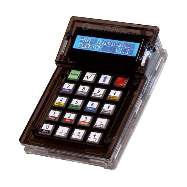
Elektor Labs Elektor Arduino MultiCalculator
Das Elektor MultiCalculator Kit ist ein Arduino-basierter Multifunktionsrechner, der über einfache Berechnungen hinausgeht. Es bietet 22 Funktionen, darunter Licht- und Temperaturmessung, Differenztemperaturanalyse und NEC-IR-Fernbedienungsdekodierung. Der Elektor MultiCalculator ist ein praktisches Werkzeug für den Einsatz in Ihren Projekten oder für Bildungszwecke. Das Kit enthält ein Pro Mini-Modul als Recheneinheit. Die Platine lässt sich mithilfe von Durchgangslochkomponenten einfach zusammenbauen. Das Gehäuse besteht aus 11 Acrylplatten und Montagematerial für eine einfache Montage. Darüber hinaus ist das Gerät mit einem 16x2 alphanumerischen LCD, 20 Tasten und Temperatursensoren ausgestattet. Der Elektor MultiCalculator ist über einen 6-Wege-PCB-Header mit der Arduino-IDE programmierbar. Der Rechner kann mit einem Programmieradapter programmiert werden und wird über USB-C mit Strom versorgt. Betriebsmodi Rechner 4-Ring-Widerstandscode 5-Ring-Widerstandscode Konvertierung von Dezimalzahlen in Hexadezimalzahlen und Zeichen (ASCII) Konvertierung von Hexadezimalzahlen in Dezimalzahlen und Zeichen (ASCII) Dezimal-zu-Binär- und Zeichen-Konvertierung (ASCII) Binär-zu-Dezimal- und Hexadezimal-Konvertierung Berechnung von Hz, nF und kapazitiver Reaktanz (XC) Hz, µH, Berechnung der induktiven Reaktanz (XL) Widerstandsberechnung zweier parallel geschalteter Widerstände Widerstandsberechnung zweier in Reihe geschalteter Widerstände Berechnung des unbekannten Parallelwiderstands Temperaturmessung Differenztemperaturmessung T1&T2 und Delta (δ) Lichtmessung Stoppuhr mit Rundenzeitfunktion Artikelzähler NEC IR-Fernbedienungsdekodierung AWG-Umwandlung (American Wire Gauge) Würfeln Startnachricht personalisieren Temperaturkalibrierung Technische Daten Menüsprachen: Englisch, Niederländisch Abmessungen: 92 x 138 x 40 mm Bauzeit: ca. 5 Stunden Lieferumfang Leiterplatten- und Durchgangslochkomponenten Vorgeschnittene Acrylplatten mit allen mechanischen Teilen Pro Mini Mikrocontroller-Modul (ATmega328/5 V/16 MHz) Programmieradapter Wasserdichte Temperatursensoren USB-C Kabel Downloads Software
€ 49,95€ 39,95
Bestpreis
-

Elektor Labs Elektor Arduino Nano MCCAB Trainingsboard
Das Elektor Arduino Nano MCCAB Trainingsboard enthält alle Bauteile (inkl. Arduino Nano), die für die Übungen des "Mikrocontroller-Praxiskurs für Arduino-Einsteiger" benötigt werden wie Leuchtdioden, Schalter, Taster, akustische Signalgeber usw. Auch externe Sensoren, Motoren oder Baugruppen können mit diesem Mikrocontroller-Übungssystem abgefragt oder gesteuert werden. Technische Daten (Arduino Nano Trainingsboard MCCAB) Stromversorgung Über die USB-Verbindung des zur Erstellung der Programme sowieso angeschlossenen PCs oder ein externes Netzteil (nicht im Lieferumfang enthalten) Betriebsspannung +5 Vcc Eingangsspannung Alle Eingänge 0 V bis +5 V VX1 und VX2 +8 V bis +12 V (nur bei Verwendung eines externen Netzteils) Mikrocontrollermodul Arduino Nano Hardwareperipherie LCD 2x16 Zeichen Potenziometer P1 & P2 JP3: Auswahl der Betriebsspannung von P1 & P2 Verteiler SV4: Verteiler für die BetriebsspannungenSV5, SV6: Verteiler für die Ein-/Ausgänge des Mikrocontrollers Schalter und Taster RESET-Taster auf dem Arduino Nano-Modul6x Tastschalter K1 … K66x Schiebeschalter S1 … S6JP2: Verbindung der Schalter mit den Eingängen des Mikrocontrollers Summer Piezo-Summer Buzzer1 mit Steckbrücke auf JP6 Leuchtanzeigen LED L auf dem Arduino Nano-Modul, verbunden mit GPIO D1311x LED: Zustandsanzeige für die Ein-/AusgängeJP6: Verbindung der LEDs LD10 … LD20 mit den GPIOs D2 … D12 Serielle SchnittstellenSPI & I²C JP4: Auswahl des Signals an Pin X der SPI-Steckerleiste SV12SV9 bis SV12: SPI-Interface (3,3 V/5 V) bzw. I²C-Interface Schaltausgang für externe Geräte SV1, SV7: Schaltausgang (maximal +24 V/160 mA, extern zugeführt)SV2: 2x13 Pins zum Anschluss externer Module 3x3 LED-Matrix (9 rote LEDs) SV3: Spalten der 3x3 LED-Matrix (Ausgänge D6 … D8)JP1: Verbindung der Reihen mit den GPIOs D3 … D5 Software Library MCCABLib Steuerung der Hardware-Komponenten (Schalter, Taster, Leuchtdioden, 3x3 LED-Matrix, Summer) auf dem MCCAB Trainingsboard Betriebstemperatur bis +40 °C Abmessungen 100 x 100 x 20 mm Technische Daten (Arduino Nano) Mikrocontroller ATmega328P Architektur AVR Betriebsspannung 5 V Flashspeicher 32 KB, davon 2 KB vom Bootloader belegt SRAM 2 KB Taktfrequenz 16 MHz Analoge IN-Pins 8 EEPROM 1 KB DC-Strom pro I/O-Pin 40 mA an einem I/O-Pin, insgesamt maximal 200 mA an allen Pins gemeinsam Eingangsspannung 7-12 V Digitale I/O-Pins 22 (6 davon sind PWM-fähig) PWM-Ausgänge 6 Stromverbrauch 19 mA Abmessungen 18 x 45 mm Gewicht 7 g Lieferumfang 1x Elektor Arduino Nano Trainingsboard (MCCAB) 1x Arduino Nano
€ 79,95
Mitglieder: € 71,96
-
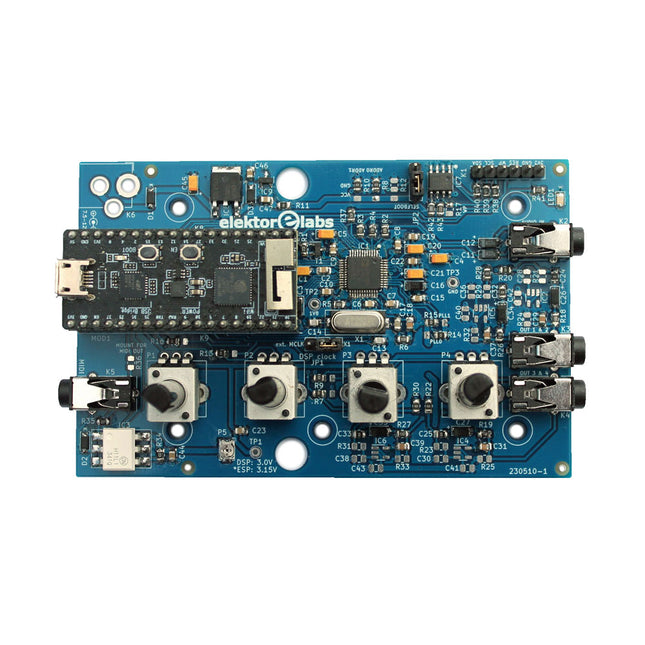
Elektor Labs Elektor Audio DSP FX Processor (Neue Revision)
Der Elektor Audio DSP FX Processor kombiniert einen ESP32-Mikrocontroller und einen ADAU1701 Audio DSP von Analog Devices. Neben einem vom Benutzer programmierbaren DSP-Kern verfügt der ADAU1701 über hochwertige integrierte Analog-Digital- und Digital-Analog-Wandler und verfügt über einen I²S-Port. Dadurch eignet es sich als hochwertiges Audio-Interface für den ESP32. Programme für den ESP32 können mit Arduino, Platform IO, CMake oder durch die Verwendung des Espressif IDF auf andere Weise erstellt werden. Programme für die Audio-DSPs ADAU7101 werden mit dem kostenlosen visuellen Programmiertool SigmaStudio durch Ziehen und Ablegen vordefinierter Algorithmusblöcke auf einer Leinwand erstellt. Anwendungen Bluetooth/Wi-Fi-Audiosink (z. B. Lautsprecher) & Quelle Gitarreneffektpedal (Stomp-Box) Musiksynthesizer Sound-/Funktionsgenerator Programmierbarer Crossover-Filter für Lautsprecher Erweiterter Audioeffektprozessor (Hall, Chorus, Pitch-Shifting usw.) Mit dem Internet verbundenes Audiogerät DSP-Experimentierplattform Drahtloses MIDI MIDI-zu-CV-Konverter und viele mehr... Technische Daten ADAU1701 28-/56-Bit, 50-MIPS digitaler Audioprozessor, der Abtastraten von bis zu 192 kHz unterstützt ESP32 32-Bit-Dual-Core-Mikrocontroller mit Wi-Fi 802.11b/g/n und Bluetooth 4.2 BR/EDR und BLE 2x 24-Bit-Audioeingänge (2 V RMS, 20 kΩ) 4x 24-Bit-Audioausgänge (0,9 V RMS, 600 Ω) 4x Steuerpotentiometer MIDI Ein- und Ausgang I²C-Erweiterungsport Multi-Mode-Betrieb Stromversorgung: 5 V DC USB oder 7,5-12 V DC (Hohlbuchse, mittlerer Pin ist GND) Stromverbrauch (Durchschnitt): 200 mA Lieferumfang 1x ESP32 Audio DSP FX Prozessor Board (montiert) 1x ESP32-PICO-KIT 2x Jumper 2x 18-Pin Header (female) 4x 10 KB Potentiometer Downloads Documentation GitHub
€ 99,95€ 84,95
Bestpreis
-
Elektor Digital Elektor Circuit Special 2023 (PDF)
Diese Ausgabe steht allen GOLD- und GREEN-Mitgliedern auf der ElektorMagazine-Website zum Download bereit! Sind Sie noch kein Mitglied? Hier klicken! Winzige Solarversorgung Sonnenlicht rein, 3,3 V raus Solid-State-Stereo-Audio-Schalter Frei von Klicks und beweglichen Teilen Große RGB-Ziffer Mit eingebauten WS2812-LEDs Mikrofonvorverstärker mit 48-V-Phantomversorgung Ideal für Podcasting und Pro Audio Rechteckgeneratoren mit Tastverhältnis- und Frequenzeinstellungssteuerung Einfache Schaltungen mit CMOS und TTL Einfacher Dynamik-Kompressor Mit sanfter Steuerung und warmem Klang Einfaches elektronisches Schloss Aktiver Gleichrichter Für 2...40 V bis 3 A mit Rückstromunterdrückung Ein/Aus-Schalter für Aktivboxen Unsymmetrisch-Symmetrisch-Wandler Mit RFI-Filter und DC-Schutz 2023: Odyssee in der KI Wo kommt sie her, wo führt sie hin? Drehzahlsteller für Lüfter oder Ventilator Manuell und mit Thermostat-Modus Das Neuste vom Arduino Project Hub Spannende Projekte aus der Community Strom-Überlast-Monitor Überwachung von Leitungen auf übermäßigen Strom Blinken im Dunkeln ohne Transistoren Ein Oszillator nur mit Zweipolen Morsecode-Generator Verwenden Sie ihn als Backen oder zum Lernen! Programmierbarer Video-DAC Verarbeitet jedes Format bis zu RGB888 Ein T(eeny)-Tiny-Piano Ohne bewegliche Teile Doppelwürfel ohne Controller Zwei Würfel auf einer Platine – plus einige Entwicklungstricks Elektronische Vogelscheuche Steuerungen, die Unterhaltung, Kontrolle und Verblüffen LC-LP-HA-Thermometer Genaue Messungen und eine binäre Anzeige THD-Generator Verzerrungen absichtlich erzeugen Übertemperaturanzeige mit Thyristor Ein unkonventionell verwendetes elektronisches Bauteil Ein PTC-Flipflop Komischer Vogel Ein zwitschernder Elektor-Klassiker Glimmlampe am Mikrocontroller Temperaturstabile IC-Stromquelle Temperaturdrift integrierter Stromquellen neutralisieren Einstellbare Höhenanhebung zweite Ordnung Eine spezielle Hörhilfe für ältere Menschen Edwin kommt nach Hause! Zurück zu den Wurzeln nach 53 Jahren Einarmiger Bandit Ein einfacher, lustiger, nostalgischer und lehrreicher Elektor-Klassiker! Einfacher digital gesteuerter variabler Widerstand Wasserleck ahoi! Schutz und Alarm in einem Öko-Timer mit automatischer Abschaltung Benötigt 0,00 mW im Aus-Modus! ChatGPT und Arduino Z-Dioden-Messgerät Messen von Z-Spannungen von Z-Dioden? 100 V Servo-Tester ESP32-Windows-Controller mit kostenloser Software Analoge und gemischte Systeme von Microchip Energieeffizientes Versorgungsmanagement und Signalverarbeitung Schnittstellen-Standards Filter und Überspannungsschutz für den I²C-Bus Li-Ion-Batterie-Monitor Restladungen bieten visuelle Rückmeldung PS/2-Maus als Drehgeber und andere Kunststücke Einfacher Dämmerungsschalter Nachrüstung von Lampen oder Installationen Wasserpumpen-Controller Bereiten Sie sich auf steigende Wasserstände vor Solarbetriebene UKW-Radio-Weihnachtsbaumkugel Alles, was Sie sich zu Weihnachten wünschen, ist genau dies Vibrationssensor mit Relais Tippen oder Schütteln zum Einschalten Durchgangsprüfer Empfindlich und unaufdringlich Ein-/Ausschalten mit einem Taster Drehzahlregler für Mini-Bohrmaschinen reloaded Überarbeitung eines Entwurfs von 1979 Digitaler Vibrationssensor Schwingungen in präzise getaktete Impulse umwandeln Verpolungsschutz mit geringem Spannungsabfall Ein billigstes Frequenznormal Winziger DCF77-Simulator Ein präziser Fake-Zeitstandard Testbericht: T-PicoC3 von LilyGO Kombination aus RP2040, ESP32-C3 und Full-Color-TFT-Display Hexadoku
€ 11,90
-
Elektor Digital Elektor Circuit Special 2024 (PDF)
Diese Ausgabe steht allen GOLD- und GREEN-Mitgliedern auf der ElektorMagazine-Website zum Download bereit! Sie sind noch kein Mitglied? Hier klicken! Digitale Last für HochstromtestsVon der Notwendigkeit zur Innovation GesangsentfernerInstant-Karaoke-Schaltung Audio-Eingangswahlschalter mit VerstärkungseinstellungSchaltet von Mikrofon- auf Line-Eingänge um Ladeschaltung für LIR2032Optimierte Ladung = längere Haltbarkeit Touch-Sensing leicht gemachtEin DIY-Leitfaden für jeden Mikrocontroller Universeller Infrarot-FernschalterEin neues Leben für alte Fernbedienungen Mikrocontroller-gesteuerte MuhdoseBovine Klänge mit einem Mikrocontroller erzeugen USB-Batterieschnittstelle Stromversorgung von Low-Power-Geräten mit PowerbanksEine Stay-Alive-Lösung Kleiner Klasse-A-Audioverstärker mit StromausgangLautsprecher mit Strom statt mit Spannung ansteuern Pseudosymmetrisches ModulHohes Gleichtaktunterdrückungsverhältnis trotz asymmetrischen Audioverbindungen Automatisches Ladegerät für Ni-MH-ZellenFüllen Sie alle Ihre Akkupacks in einem Rutsch auf! Sicherheit durch thyristor-basierte Strombegrenzung Fingerabdruck-Sensor-SchalterEin nützliches Gerät zum Identitätsnachweis 3-A-GleichspannungswandlerBessere Nutzung Ihrer Festspannungsquellen Innovationen aus dem Arduino-Project-HubNeue Projekte aus der Community Fernkontrolle eines BoilersSpannungs- und Stromdetektion für Netzspannungsleitungen Abschwächer für AudiosignaleTeil 1. Einstellbar über Jumper Autobatterie-Ladegerät aufgemotztTeil 1. Wiederverwenden statt wegwerfen! Eine Platine für „The Blue One“Platine für Alps-Motorpotentiometer mit Rückmeldung 50-Hz-Referenz aus 60-Hz-NetzspannungWie man 50-Hz-Elektronik in 60-Hz-Umgebungen verwendet Digitale IsolatorenGalvanische Trennung einfach realisieren Kompakter 12-W-Hi-Fi-MonoverstärkerKlein, aber leistungsstark LM386-Rampengenerator DrehstromgeneratorMit Raspberry Pi Pico Türöffner für musikalisch Begabte Elektor-Klassiker: Surf-SynthesizerMeereswassersporthintergrundgeräuschgenerator (Mwsh3g) Autobatterie-Ladegerät aufgemotztTeil 2. Ladesteuerung analog und digital LampenstromüberwachungMit Raspberry Pi Pico Infrarot-Telegraphie Fnirsi SWM-10Reparatur von Batteriepacks mit tragbarem intelligentem Punktschweißgerät Stereo-Audio-Codec für ESP32 und Co.Keine Angst vor Audio-Messtechnik Die Kunst des LötensLötzinn-Techniken für einwandfreie Verbindungen Abschwächer für AudiosignaleTeil 2. Umschalten per Relais USB-C-PowerStrom aus USB-C-Netzteilen beziehen Drei Schaltungen mit zwei und drei Zähler-ICs4017-ICs im Zusammenspiel Aktive Bauelemente – Die Diode Timer für extrem lange VerzögerungenEinstellen und vergessen! Klinke rein, Klinke rausEine nützlicher Anschluss für Audioschaltungen ESP32 mit nur einer Lithium-Zelle versorgen Hexadoku
€ 11,90
-
Elektor Circuit Special 2025 (DE)
Diese Ausgabe steht allen GOLD- und GREEN-Mitgliedern auf der ElektorMagazine-Website zum Download bereit! Sie sind noch kein Mitglied? Hier klicken! USB-MessadapterStrom und Signalqualität von USB-Anschlüssen testen 4...20 mA Stromausgang für Arduino UnoEine zuverlässige, EMI-unempfindliche Stromschleifenschnittstelle Automatische StaubsaugersteuerungHalten Sie den Arbeitsbereich Ihrer Werkzeuge sauber DDS-Generator mit ATtiny Opamp-Tester V2Neue Platine – nun auch für SMDs geeignet 550-mW-„Lamp“-AudioverstärkerDer warme Klang von Röhren – ganz einfach SicherungswächterSicherung mit Blink-LED überwachen Hochwertiger RIAA-VorverstärkerHolen Sie das Beste aus Ihren Vinyl-Schallplatten heraus! Drahzahlkalibrator für PlattenspielerEin Arduino-basierter Stroboskopgenerator mit 100–120 Hz Infrarot-fernbedienbarer DimmerSteuern Sie Ihre Halogen- oder LED-Stehleuchte mühelos und mit Stil Wie man switch…case mit Strings in C++/Arduino IDE verwendet Magnetfindermit einfachem Hall-Effekt-Sensor Intelligenter Einschaltknopf für Raspberry PiEine Lösung für Raspberry Pi bis zum Modell 4 Essenzielle Maker-TippsProfessionelle Einblicke für den Maker-Alltag Praktische Projekte mit dem 555-TimerGleichstrommotorsteuerung und Reaktionszeitschallungen Einfacher AC-Last-Ein-MonitorEnergie sparen mit einem einfachen Gerät Powerbanks parallel schaltenEine durchgehende Stromversorgung für drei Tage VFO bis 15 MHzMit Raspberry Pi Pico Geigen-Stimmgerät mit ATtiny202 Elektor Classics: Video-Eingangsverstärker für S/W-Fernseher Kapazitätsmesser20 pF bis 600 nF Quasi-analoges Uhrwerk MkIIZwei LED-Ringe für Stunden und Minuten Sie können alles tun, was Sie wollen(mit dem Arduino-Ökosystem an Ihrer Seite) Neon-Würfel mit Glimmlampen Elektor Classics: Video-Verstärker Inspirierende Hardware-Designs für Ihre ESPs Elektor Classics: RTTY-Abgleichanzeige RGB-LEDs mit integrierter SteuerschaltungLicht mit Präzision: ICLEDs setzen Maßstäbe Experiment: Auf dem Weg zu einem Mixed-Signal-Theremin?Moderne Time-of-Flight-Sensoren im Zusammenspiel mit dem zeitlosen XR2206-Analoggenerator ESP32-Audio-Transceiver-Board (Teil 1)SD-Karten-WAV-Player-Demo Infografiken: Schaltungen & Schaltungsdesign 2025 Kleiner Audio-MixerEinfaches und vielseitiges skalierbares Design Intelligenter Treppenlicht-TimerEffiziente Lichtsteuerung zur Reduzierung des Energieverbrauchs Machen Sie Ihre Rollläden smartVelux-Hardware steuern mit ESP32 und MQTT Solid-State-FußwärmerEnergieeffizienter Komfort Ist der M5Stamp Fly Quadcopter der nächste Tello? Erhöhung der WLAN-Reichweite des ESP32-C3 SuperMiniEine einfache und wirkungsvolle Antennenmodifikation ZD-8968 Heißluft-LötstationEin preisgünstiges Arbeitstier oder nur heiße Luft? Parksensor-TesterDefekte beim PDC-System am Auto finden
€ 15,90
-
Elektor Digital Elektor Circuit Special 2025 (PDF) DE
Diese Ausgabe steht allen GOLD- und GREEN-Mitgliedern auf der ElektorMagazine-Website zum Download bereit! Sie sind noch kein Mitglied? Hier klicken! USB-MessadapterStrom und Signalqualität von USB-Anschlüssen testen 4...20 mA Stromausgang für Arduino UnoEine zuverlässige, EMI-unempfindliche Stromschleifenschnittstelle Automatische StaubsaugersteuerungHalten Sie den Arbeitsbereich Ihrer Werkzeuge sauber DDS-Generator mit ATtiny Opamp-Tester V2Neue Platine – nun auch für SMDs geeignet 550-mW-„Lamp“-AudioverstärkerDer warme Klang von Röhren – ganz einfach SicherungswächterSicherung mit Blink-LED überwachen Hochwertiger RIAA-VorverstärkerHolen Sie das Beste aus Ihren Vinyl-Schallplatten heraus! Drahzahlkalibrator für PlattenspielerEin Arduino-basierter Stroboskopgenerator mit 100–120 Hz Infrarot-fernbedienbarer DimmerSteuern Sie Ihre Halogen- oder LED-Stehleuchte mühelos und mit Stil Wie man switch…case mit Strings in C++/Arduino IDE verwendet Magnetfindermit einfachem Hall-Effekt-Sensor Intelligenter Einschaltknopf für Raspberry PiEine Lösung für Raspberry Pi bis zum Modell 4 Essenzielle Maker-TippsProfessionelle Einblicke für den Maker-Alltag Praktische Projekte mit dem 555-TimerGleichstrommotorsteuerung und Reaktionszeitschallungen Einfacher AC-Last-Ein-MonitorEnergie sparen mit einem einfachen Gerät Powerbanks parallel schaltenEine durchgehende Stromversorgung für drei Tage VFO bis 15 MHzMit Raspberry Pi Pico Geigen-Stimmgerät mit ATtiny202 Elektor Classics: Video-Eingangsverstärker für S/W-Fernseher Kapazitätsmesser20 pF bis 600 nF Quasi-analoges Uhrwerk MkIIZwei LED-Ringe für Stunden und Minuten Sie können alles tun, was Sie wollen(mit dem Arduino-Ökosystem an Ihrer Seite) Neon-Würfel mit Glimmlampen Elektor Classics: Video-Verstärker Inspirierende Hardware-Designs für Ihre ESPs Elektor Classics: RTTY-Abgleichanzeige RGB-LEDs mit integrierter SteuerschaltungLicht mit Präzision: ICLEDs setzen Maßstäbe Experiment: Auf dem Weg zu einem Mixed-Signal-Theremin?Moderne Time-of-Flight-Sensoren im Zusammenspiel mit dem zeitlosen XR2206-Analoggenerator ESP32-Audio-Transceiver-Board (Teil 1)SD-Karten-WAV-Player-Demo Infografiken: Schaltungen & Schaltungsdesign 2025 Kleiner Audio-MixerEinfaches und vielseitiges skalierbares Design Intelligenter Treppenlicht-TimerEffiziente Lichtsteuerung zur Reduzierung des Energieverbrauchs Machen Sie Ihre Rollläden smartVelux-Hardware steuern mit ESP32 und MQTT Solid-State-FußwärmerEnergieeffizienter Komfort Ist der M5Stamp Fly Quadcopter der nächste Tello? Erhöhung der WLAN-Reichweite des ESP32-C3 SuperMiniEine einfache und wirkungsvolle Antennenmodifikation ZD-8968 Heißluft-LötstationEin preisgünstiges Arbeitstier oder nur heiße Luft? Parksensor-TesterDefekte beim PDC-System am Auto finden
€ 11,90
-
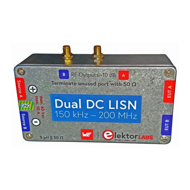
Elektor Labs Elektor Dual DC LISN (150 kHz – 200 MHz)
Die Messung der leitungsgebundenen Emission ist die einfachste und kostengünstigste Methode, um einen Hinweis darauf zu erhalten, ob ein Design die EMI/EMV-Anforderungen erfüllen kann. Ein Line Impedance Stabilization Network (LISN) ist dabei ein unverzichtbarer Bestandteil eines EMV-Prüfaufbaus (Pre-Compliance). In Zusammenarbeit mit Würth Elektronik hat Elektor einen 5 µH, 50 Ω Dual DC LISN entwickelt, der Spannungen bis zu 60 V und Ströme bis zu 10 A unterstützt. Das Gerät misst HF-Störungen auf beiden Kanälen (der Stromversorgung) mit Hilfe von 5-μH-Sperrinduktivitäten. Das interne 10-dB-Dämpfungsnetzwerk – eines in jedem Kanal – enthält einen Hochpassfilter dritter Ordnung mit einer Grenzfrequenz von 9 kHz, um den Eingang von Instrumenten wie z. B. einem Spektrumanalysator vor potenziell schädlichen Gleichspannungen oder niedrigen Frequenzen zu schützen, die vom Prüfling (EUT – Equipment Under Test) stammen. Technische Daten RF-Pfad Kanäle 2 (mit Klemmdioden) Bandbreite 150 kHz – 200 MHz Induktivität 5 μH || 50 Ω Interne Abschwächung 10 dB Steckverbinder SMA DC-Pfad Max. Strom < 10 ADC Max. Spannung < 60 VDC DC-Widerstand < 2 x 70 mΩ Platinengröße 94,2 x 57,4 mm Steckverbinder 4-mm-Bananenstecker Hammond-Gehäuse Typ 1590N Abmessungen 121 x 66 x 40 mm Lieferumfang 1x 4-lagige Platine mit allen SMD-Bauteilen bestückt 1x Vorgebohrtes Gehäuse mit vorgedrucktem Frontplattenlayout 5x Vergoldete, isolierte 4-mm-Bananenbuchsen, ausgelegt für 24 A, 1 kV 1x Hammond-Gehäuse 1590N1, Aluminium (Druckgusslegierung) Mehr Info Projekt auf Elektor Labs: Dual DC LISN for EMC pre-compliance testing Elektor 9-10/2021: EMV-Vor-Konformitätstester für Ihr Projekt mit DC-Versorgung (Teil 1) Elektor 11-12/2021: EMV-Vorkonformitätstest für Ihr DC-versorgtes Projekt (Teil 2)
-

Elektor Edge Impulse Guest Edition 2025 (DE)
Diese Ausgabe steht allen GOLD- und GREEN-Mitgliedern auf der ElektorMagazine-Website zum Download bereit! Sie sind noch kein Mitglied? Hier klicken! Was genau ist eigentlich Edge-KI?Intelligenz direkt im Gerät Wir stellen vor: Edge Impulse StudioKI-Modelle für Edge-Geräte einfach erstellen und bereitstellen Keyword Spotting mit Edge ImpulseErfassen, Trainieren und Implementieren Intelligente Gerätesteuerung per Sprachbefehl mit Nordic Thingy:53 Edge-KISchlüsselbegriffe zum Verständnis von Edge-KI und Machine Learning Crashkurs: Einstieg in Edge ImpulseWie Sie mit dem Arduino Nano 33 BLE Sense ein ML-Modell erfassen, trainieren und bereitstellen Ein neues Kapitel für ArduinoVom Hobby-Board zur Edge-Computing-Plattform Erste Schritte mit Objekterkennung auf Edge-Geräten Fehlererkennung auf LeiterplattenComputer Vision mit dem Raspberry Pi KI-Skalierung für kleinste Geräte Optimierung der Energieeffizienz bei batteriebetriebenen Edge-KI-Geräten KI-ToasterWenn Edge-KI das Frühstück rettet Thundercomm Rubik Pi 3Raspberry Pi trifft Edge-KI Unternehmensführung, Embedded ML und die Edge-Revolution Vision-Language-Modelle für Edge-GeräteKaskadierte Modelle für höhere Zuverlässigkeit Lernen Sie Edge Impulse kennenFragen aus der Elektor-Community Projekt-Update #5: Energiemessgerät mit ESP32Haushaltsgeräte mit Edge-KI erkennen Bewegungserkennung mit Anomalie-ErkennungEin End-to-End-Tutorial Intelligentes Belüftungssystem: Verbindung von Schall- und UmweltdatenEin Dual-MCU-Ansatz mit Machine Learning für die automatische Steuerung von Fenstern und Jalousien Sprachsteuerung für Ohrhörer und Headsets Edge-KI: Intelligente Geräte auf dem Vormarsch
€ 15,90


