Das LoRa-E5 Development Kit ist ein benutzerfreundliches, kompaktes Entwicklungs-Toolset, mit dem Sie die leistungsstarke Leistung des LoRa-E5 STM32WLE5JC nutzen können. Es besteht aus einem LoRa-E5-Entwicklungsboard, einer Antenne (EU868), einem USB-Typ-C-Kabel und einem 2 AA 3-V-Batteriehalter. LoRa-E5-Entwicklungsplatine mit eingebettetem LoRa-E5-STM32WLE5JC-Modul, das die weltweit erste Kombination aus LoRa-HF- und MCU-Chip in einem einzigen winzigen Chip ist und FCC- und CE-zertifiziert ist. Es wird von einem ARM Cortex-M4-Kern und einem Semtech SX126X LoRa-Chip angetrieben und unterstützt sowohl das LoRaWAN- als auch das LoRa-Protokoll auf der weltweiten Frequenz sowie (G)FSK-, BPSK-, (G)MSK- und LoRa-Modulationen. Das LoRa-E5-Entwicklungsboard zeichnet sich durch eine extrem lange Übertragungsreichweite, einen extrem niedrigen Stromverbrauch des Chips und benutzerfreundliche Schnittstellen aus. Das LoRa-E5-Entwicklungsboard hat eine Langstrecken-Übertragungsreichweite von LoRa-E5 von bis zu 10 km in einem offenen Bereich. Der Ruhestrom der LoRa-E5-Module an Bord beträgt nur 2,1 uA (WOR-Modus). Es wurde nach Industriestandards mit einem breiten Arbeitstemperaturbereich von -40℃ ~ 85℃, hoher Empfindlichkeit zwischen -116,5 dBm bis -136 dBm und einer Ausgangsleistung von bis zu +20,8 dBm bei 3,3 V entwickelt. LoRa-E5 Dev Board hat auch umfangreiche Schnittstellen. Entwickelt, um die volle Funktionalität des LoRa-E5-Moduls freizuschalten, hat das LoRa-E5-Entwicklungsboard volle 28 Pins von LoRa-E5 herausgeführt und bietet umfangreiche Schnittstellen, darunter Grove-Anschlüsse, RS-485-Anschluss, männliche/weibliche Stiftleisten für Sie Verbinden Sie Sensoren und Module mit verschiedenen Anschlüssen und Datenprotokollen und sparen Sie Zeit beim Löten von Drähten. Sie können das Board auch einfach mit Strom versorgen, indem Sie den Batteriehalter mit 2 AA-Batterien verbinden, was eine vorübergehende Verwendung ermöglicht, wenn keine externe Stromquelle vorhanden ist. Es ist ein benutzerfreundliches Board für einfaches Testen und schnelles Prototyping. Technische Daten Abmessungen LoRa-E5 Dev Board: 85,6 x 54 mm Spannung (Versorgung) 3-5 V (Batterie) / 5 V (USB-C) Spannung (Ausgang) EN 3V3 / 5 V Leistung (Ausgang) Bis zu +20,8 dBm bei 3,3 V Frequenz EU868 Protokoll LoRaWAN Empfindlichkeit -116,5 dBm ~ -136 dBm Schnittstellen USB-C / JST2.0 / 3x Grove (2x I²C/1x UART) / RS485 / SMA-K / IPEX Modulation LoRa, (G)FSK, (G)MSK, BPSK Betriebstemperatur -40℃ ~ 85℃ Strom LoRa-E5-Modul mit nur 2,1 uA Ruhestrom (WOR-Modus) Lieferumfang 1x LoRa-E5 Dev Board 1x Antenne (EU868) 1x USB-C-Kabel (20 cm) 1x 2 AA 3-V-Batteriehalter
Dies ist eine leistungsstarke Kühllösung, die darauf ausgelegt ist, Wärme effektiv abzuleiten und optimale Betriebstemperaturen für den Raspberry Pi sicherzustellen. Es ist ein unverzichtbares Zubehör für Benutzer, die die Leistung und Langlebigkeit ihres Raspberry Pi-Geräts verbessern möchten.
Das kompakte Design des Wasserkühlungskits für Raspberry Pi 5 ermöglicht die nahtlose Installation auf der Ober- und Unterseite des Raspberry Pi 5, wodurch eine effiziente Wärmeübertragung gewährleistet und die Unterseite des Raspberry Pi perfekt geschützt wird . Dank des einfachen Installationsprozesses ist keine komplexe Verkabelung oder zusätzliches Werkzeug erforderlich, sodass es sowohl für Anfänger als auch für erfahrene Raspberry-Pi-Enthusiasten geeignet ist.
Mit seiner leistungsstarken Kühlleistung leitet das Wasserkühlungsset für Raspberry Pi 5 die vom Raspberry Pi bei intensiven Aufgaben oder längerer Nutzung erzeugte Wärme effektiv ab. Dies verhindert eine Überhitzung und sorgt für eine stabile Leistung. Eine effiziente wassergekühlte Kühlung ermöglicht es Ihnen, mehrere Raspberry Pi-Boards an eine Reihe von Kühlgeräten anzuschließen. Wenn Sie Raspberry Pi in einem Cluster verwenden, können Sie eine Reihe wassergekühlter Geräte verwenden, um mehrere Raspberry Pi-Boards effektiv zu kühlen.
Features
Hergestellt für Raspberry Pi: Speziell für Raspberry Pi 5 entwickelt, 1:1-Formöffnung, deckt alle Wärmequellen ab, einschließlich CPU, WLAN, Power-Chip und eMMC.
Kühlleistung: Leitet die vom Raspberry Pi erzeugte Wärme effektiv ab, sorgt für optimale Betriebstemperaturen und verhindert Überhitzung.
Einfach zu bedienen: Das integrierte Design der Wasserpumpe und des Kühlventilators ist für Benutzer bequem zu installieren.
RGB-Farbbeleuchtung: An den Lüfter- und Wasserpumpenstandorten sind RGB-Farblichter installiert.
Lieferumfang
1x Wasserkühlungsset
1x Wasserkühlungskühler
1x schwarzer Kühlkörper
2x Silikonschlauch
1x 12 V/2 A Netzteil (US)
4x Sechskantschraube M2,5x10
1x L-Schlüssel-Inbusschlüssel
You can use RF Explorer 3G Combo equally well outdoor and indoor, and you can also connect it to a PC for extra functionality using standard mini-USB 2.0 connector.
This model includes a WSUB1G baseline unit plus an RFEMWSUB3G Expansion Module conveniently assembled and tested. It comes with two SMA connectors and two antennas,a dual band telescopic 144 / 430 MHz antenna for all Sub-GHz frequencies and a whip helical antenna for 2.4 GHz band. Additional, specific band antennas may be needed to cover efficiently some of the frequencies supported.
The combination of these two models offer the wide band coverage of the WSUB3G module, together with the highest sensitivity and quick response of the WSUB1G model for the popular sub-1GHz frequencies.
Features
Pocket size and light weight
Solid aluminum metal case
Includes a transport EVA carry case for RF Explorer
Spectrum Analyzer mode with Peak Max and Hold, Normal, Overwrite and Averaging modes
Lifetime free firmware upgrades available, open to community requested features
High capacity Lipo for 16 hours+ of continuous run, rechargeable by USB
Windows PC client Open Source
Can be extended with internal Expansion Modules for additional band and functionality
Wide band coverage to all popular RF frequencies, starting at 15 MHz and going up to 2.7 GHz. This includes very interesting frequency areas such as 2 m HAM radio, all VHF and UHF, FM radio, GPS, WiFi and WiMax, Bluetooth, etc.
Firmware: RF Explorer 3G Combo is delivered with upgraded firmware v1.09. Note some of the features and operation accuracy will be improved in upcoming free firmware revisions.
Specifications
Battery
Lithium Cells / Batteries contained in equipment UN3481 - PI967
Frequency band
15-2700 MHz
Frequency span
112 KHz - 600 MHz
Graphics LCD
128 x 64 pixels, great visibility outdoors
PC Windows client
supports Windows XP/Vista/Win7 both 32 and 64bits
Backlight
for great indoor visibility
2 standard SMA 50 ohms connector,
one for Sub-GHz wideband Nagoya NA-773 telescopic antenna included and another 2.4 GHz one for 15-2700 MHz band with helical antenna included.
Amplitude resolution
0.5 dBm
Dynamic range
Left SMA port (WSUB1G)
-115 dBm to 0 dBm
Right SMA port (WSUB3G)
-110 dBm to -10 dBm
Absolute Max input power
Left SMA port (WSUB1G)
+5 dBm
Right SMA port (WSUB3G)
+30 dBm
Average noise level (typical)
-110 dBm
Frequency stability and accuracy (typical)
+-10 ppm
Amplitude stability and accuracy (typical)
+-6 dBm
Frequency resolution
1 KHz
Resolution bandwidth (RBW)
automatic 3 KHz to 600 KHz
Weight
185 g
Size
113 x 70 x 25 mm
Included
RF Explorer 3G Combo
Nagoya NA-773 wideband telescopic antenna
2.4 GHz band antenna
EVA Case
Documentation
For more info and to get started with your RF Explorer, visit the start page.
For questions and support, please visit https://support.rf-explorer.com
Features
Internal LNA amplifier and selectable attenuator
Low frequency support from 50KHz covering LF, MF, HF, VHF and UHF up to 960Mhz
New HELP and SET buttons to improve user interface and configuration selection with 2-clicks
Wide band coverage to all popular sub-1Ghz bands, including FM, TV and DTV, ISM, RFID, GSM, etc.
Ideal choice for HAM bands from 160meters to 33cm
Pocket size and light weight
Solid metal case
Spectrum Analyzer mode with Peak Max and Hold, Normal, Overwrite and Averaging modes
High capacity internal Lithium battery for 20hs+ of continuous run, rechargeable by USB
Multi-platform Windows/Linux/MacOS Open Source software and API libraries
Can be extended with internal Expansion Modules for additional band and functionality
Specifications
Frequency band: 0.05 MHz - 960 MHz
Frequency span: 0.1 MHz - 960 MHz
Internal selectable LNA 25 dB gain
Internal selectable Attenuator 30 dB
Graphics LCD 128 x 64 pixels, great visibility outdoors
Support included for Windows, Linux and MacOS X
Backlight for great visibility indoor
Internal Lithium Ion 1800mA/h rechargeable battery
Standard SMA 50 Ω connector
Wideband 144/433MHz dual band telescopic antenna included
UHF 400-900 MHz rubber duck articulated antenna included
Amplitude resolution: 0.5dBm
Dynamic range: -125 dBm to 10 dBm
Absolute Max input power: +30dBm
Average noise level (typical LNA): -125 dBm
Frequency stability and accuracy (typical): +-10 ppm
Amplitude stability and accuracy (typical): +-2d Bm
Frequency resolution: 1kHz
Resolution bandwidth (RBW): automatic 2.6 kHz to 600 kHz
Included
1x RF Explorer WSUB1G+ Spectrum Analyzer
1x Mini USB cable
1x Dual band 144/430MHz Telescopic antenna
1x UHF 400-900Mhz antenna
1x EVA case
This book details the use of the Arduino Uno and the Raspberry Pi 4 in practical CAN bus based projects. Using either the Arduino Uno or the Raspberry Pi with off-the-shelf CAN bus interface modules considerably ease developing, debugging, and testing CAN bus based projects.
This book is written for students, practicing engineers, enthusiasts, and for everyone else wanting to learn more about the CAN bus and its applications. The book assumes that the reader has some knowledge of basic electronics. Knowledge of the C and Python programming languages and programming the Arduino Uno using its IDE and Raspberry Pi will be useful, especially if the reader intends to develop microcontroller-based projects using the CAN bus.
The book should be a useful source of reference material for anyone interested in finding answers to questions such as:
What bus systems are available for the automotive industry?
What are the principles of the CAN bus?
How can I create a physical CAN bus?
What types of frames (or data packets) are available in a CAN bus system?
How can errors be detected in a CAN bus system and how dependable is a CAN bus system?
What types of CAN bus controllers exist?
How do I use the MCP2515 CAN bus controller?
How do I create 2-node Arduino Uno-based CAN bus projects?
How do I create 3-node Arduino Uno-based CAN bus projects?
How do I set the acceptance masks and acceptance filters?
How do I analyze data on the CAN bus?
How do I create 2-node Raspberry Pi-based CAN bus projects?
How do I create 3-node Raspberry Pi-based CAN bus projects?
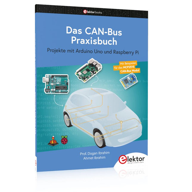
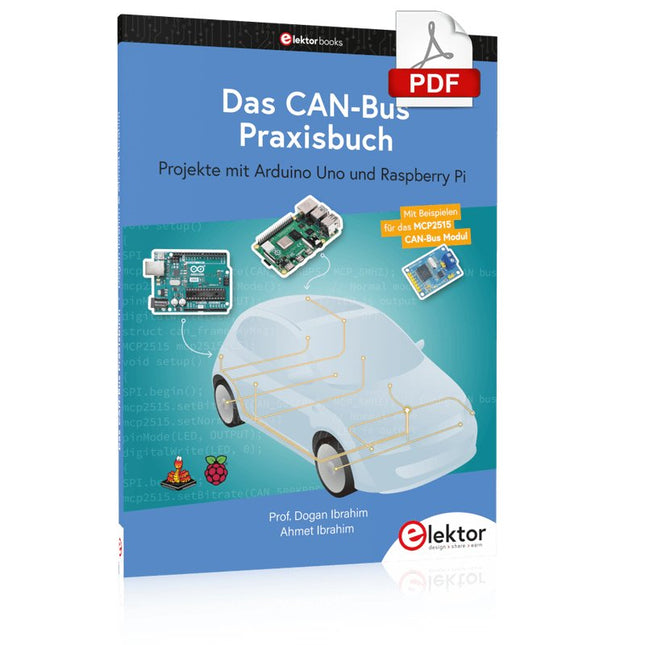
Projekte mit Arduino Uno und Raspberry Pi
In diesem Buch werden Anwendungen von Arduino Uno und Raspberry Pi 4 in praxisnahen Projekten auf Basis von CAN-Bus detailliert beschrieben. Durch den Einsatz von entweder Arduino Uno oder Raspberry Pi in Verbindung mit handelsüblichen CAN-Bus-Schnittstellenmodulen werden die Entwicklung, Fehlersuche und Fehlerbeseitigung sowie die Überprüfung von Projekten auf CAN-Bus-Basis erheblich erleichtert.
Dieses Buch richtet sich an jeden, der mehr über den CAN-Bus lernen möchte und mit den Grundlagen der Elektronik vertraut ist. Hilfreich ist auch Erfahrung mit den Programmiersprachen C und Python sowie mit der Programmierung von Arduino Uno unter Verwendung seiner IDE und von Raspberry Pi zu haben.
Das Buch ist eine nützliche Informationsquelle und ein Nachschlagewerk für jeden, der Antworten auf eine oder mehrere der folgenden Fragen sucht:
Welche Bussysteme stehen für die Automobilindustrie zur Verfügung?
Was sind die Grundprinzipien des CAN-Bus?
Welche Arten von Frames (oder Datenpaketen) stehen in einem CAN-Bussystem zur Verfügung?
Wie können Fehler in einem CAN-Bussystem erkannt werden, und wie zuverlässig ist ein CAN-Bussystem?
Welche Arten von CAN-Bus-Controllern gibt es?
Welches sind die Funktionsprinzipien des MCP2515 CAN-Bus-Controllers?
Wie kann ich ein CAN-Bus-Projekt mit Arduino Uno realisieren?
Wie kann ich Arduino oder Raspberry Pi CAN-Bus-Projekte mit 2 und 3 Knoten erstellen?
Wie kann ich die Daten auf dem CAN-Bus analysieren?
Wie kann ich ein CAN-Bus-Projekt mit Raspberry Pi ausführen?
Projekte mit Arduino Uno und Raspberry Pi
In diesem Buch werden Anwendungen von Arduino Uno und Raspberry Pi 4 in praxisnahen Projekten auf Basis von CAN-Bus detailliert beschrieben. Durch den Einsatz von entweder Arduino Uno oder Raspberry Pi in Verbindung mit handelsüblichen CAN-Bus-Schnittstellenmodulen werden die Entwicklung, Fehlersuche und Fehlerbeseitigung sowie die Überprüfung von Projekten auf CAN-Bus-Basis erheblich erleichtert.
Dieses Buch richtet sich an jeden, der mehr über den CAN-Bus lernen möchte und mit den Grundlagen der Elektronik vertraut ist. Hilfreich ist auch, Erfahrungen mit den Programmiersprachen C und Python sowie mit der Programmierung von Arduino Uno unter Verwendung seiner IDE und von Raspberry Pi zu haben.
Das Buch ist eine nützliche Informationsquelle und ein Nachschlagewerk für jeden, der Antworten auf eine oder mehrere der folgenden Fragen sucht:
Welche Bussysteme stehen für die Automobilindustrie zur Verfügung?
Was sind die Grundprinzipien des CAN-Bus?
Welche Arten von Frames (oder Datenpaketen) stehen in einem CAN-Bussystem zur Verfügung?
Wie können Fehler in einem CAN-Bussystem erkannt werden, und wie zuverlässig ist ein CAN-Bussystem?
Welche Arten von CAN-Bus-Controllern gibt es?
Was sind die Funktionsprinzipien des MCP2515 CAN-Bus-Controllers?
Wie kann ich ein CAN-Bus-Projekt mit Arduino Uno realisieren?
Wie kann ich Arduino- oder Raspberry Pi-CAN-Bus-Projekte mit 2 und 3 Knoten erstellen?
Wie kann ich die Daten auf dem CAN-Bus analysieren?
Wie kann ich ein CAN-Bus-Projekt mit Raspberry Pi ausführen?
Projects with Arduino Uno & Raspberry Pi with Examples for the MCP2515 CAN Bus Interface Module
This book details the use of the Arduino Uno and the Raspberry Pi 4 in practical CAN bus based projects. Using either the Arduino Uno or the Raspberry Pi with off-the-shelf CAN bus interface modules considerably ease developing, debugging, and testing CAN bus based projects.
This book is written for students, practicing engineers, enthusiasts, and for everyone else wanting to learn more about the CAN bus and its applications. The book assumes that the reader has some knowledge of basic electronics. Knowledge of the C and Python programming languages and programming the Arduino Uno using its IDE and Raspberry Pi will be useful, especially if the reader intends to develop microcontroller-based projects using the CAN bus.
The book should be a useful source of reference material for anyone interested in finding answers to questions such as:
What bus systems are available for the automotive industry?
What are the principles of the CAN bus?
How can I create a physical CAN bus?
What types of frames (or data packets) are available in a CAN bus system?
How can errors be detected in a CAN bus system and how dependable is a CAN bus system?
What types of CAN bus controllers exist?
How do I use the MCP2515 CAN bus controller?
How do I create 2-node Arduino Uno-based CAN bus projects?
How do I create 3-node Arduino Uno-based CAN bus projects?
How do I set the acceptance masks and acceptance filters?
How do I analyze data on the CAN bus?
How do I create 2-node Raspberry Pi-based CAN bus projects?
How do I create 3-node Raspberry Pi-based CAN bus projects?
Dieses Wi-Fi-Modul basiert auf dem beliebten ESP8266-Chip. Das Modul ist FCC- und CE-zertifiziert und RoHS-konform.
Voll kompatibel mit ESP-12E. 13 GPIO-Pins, 1 Analogeingang, 4 MB Flash-Speicher.
Grundlagen und Selbstbau
Weshalb nicht damit beginnen, Mikrocontroller-Module selbst zu entwickeln, zumindest aber sich in Gedanken mit solchen Aufgaben zu beschäftigen? Wie Mikrocontroller-Module aufgebaut sind und wozu sie verwendet werden, soll in 'Mikrocontroller-Module – Grundlagen und Selbstbau' dargestellt werden.
Das vorliegende Buch beleuchtet Mikrocontroller-Module, die vor allem zum Experimentieren, zum Lernen und zum Einarbeiten in die Entwicklung und Programmierung von Embedded Systems gedacht sind.
Die Entwurfsgrundsätze, Lösungsvorschläge und Projekte, die in diesem Buch beschrieben werden, sind aus zwei Ideen hervorgegangen: Erstens können neue Entwicklungen zwischen den weit verbreiteten kostengünstigen Mikrocontroller-Modulen und der industriellen Computer- und Steuerungstechnik ihren Platz finden und zweitens ist es eine Herausforderung an sich, solche Module zu entwickeln und einzusetzen.
In den ersten sieben Kapiteln dieses Buches werden die technischen Grundlagen diskutiert und anhand eigener Entwicklungen veranschaulicht. Das achte Kapitel gibt einen Überblick über diesen Modulbaukasten.
Alle Fotos aus dem Buch können hier vierfarbig heruntergeladen werden.
Mastering the I²C Bus takes you on an exploratory journey of the I²C Bus and its applications. Besides the Bus protocol, plenty of attention is given to the practical applications and designing a stable system. The most common I²C compatible chip classes are covered in detail.
Two experimentation boards are available that allow for rapid prototype development. These boards are completed by a USB to I²C probe and a software framework to control I²C devices from your computer. All samples programs can be downloaded from the 'Attachments/Downloads' section on this page.
Projects built on Board 1:
USB to I²C Interface, PCA 9534 Protected Input, PCA 9534 Protected Output, PCA 9553 PWM LED Controller, 24xxx EEPROM Module, LM75 Temperature Sensor, PCA8563 Real-time Clock with Battery Backup, LCD and Keyboard Module, Bus Power Supply.
Projects built on Board 2:
Protected Input, Protected Output, LM75 Temperature Sensor, PCF8574 I/O Board, SAA1064 LED Display, PCA9544 Bus Expander, MCP40D17 Potentiometer, PCF8591 AD/DA, ADC121 A/D Converter, MCP4725 D/A Converter, 24xxx EEPROM Module.