Das LoRa-E5 Development Kit ist ein benutzerfreundliches, kompaktes Entwicklungs-Toolset, mit dem Sie die leistungsstarke Leistung des LoRa-E5 STM32WLE5JC nutzen können. Es besteht aus einem LoRa-E5-Entwicklungsboard, einer Antenne (EU868), einem USB-Typ-C-Kabel und einem 2 AA 3-V-Batteriehalter. LoRa-E5-Entwicklungsplatine mit eingebettetem LoRa-E5-STM32WLE5JC-Modul, das die weltweit erste Kombination aus LoRa-HF- und MCU-Chip in einem einzigen winzigen Chip ist und FCC- und CE-zertifiziert ist. Es wird von einem ARM Cortex-M4-Kern und einem Semtech SX126X LoRa-Chip angetrieben und unterstützt sowohl das LoRaWAN- als auch das LoRa-Protokoll auf der weltweiten Frequenz sowie (G)FSK-, BPSK-, (G)MSK- und LoRa-Modulationen. Das LoRa-E5-Entwicklungsboard zeichnet sich durch eine extrem lange Übertragungsreichweite, einen extrem niedrigen Stromverbrauch des Chips und benutzerfreundliche Schnittstellen aus. Das LoRa-E5-Entwicklungsboard hat eine Langstrecken-Übertragungsreichweite von LoRa-E5 von bis zu 10 km in einem offenen Bereich. Der Ruhestrom der LoRa-E5-Module an Bord beträgt nur 2,1 uA (WOR-Modus). Es wurde nach Industriestandards mit einem breiten Arbeitstemperaturbereich von -40℃ ~ 85℃, hoher Empfindlichkeit zwischen -116,5 dBm bis -136 dBm und einer Ausgangsleistung von bis zu +20,8 dBm bei 3,3 V entwickelt. LoRa-E5 Dev Board hat auch umfangreiche Schnittstellen. Entwickelt, um die volle Funktionalität des LoRa-E5-Moduls freizuschalten, hat das LoRa-E5-Entwicklungsboard volle 28 Pins von LoRa-E5 herausgeführt und bietet umfangreiche Schnittstellen, darunter Grove-Anschlüsse, RS-485-Anschluss, männliche/weibliche Stiftleisten für Sie Verbinden Sie Sensoren und Module mit verschiedenen Anschlüssen und Datenprotokollen und sparen Sie Zeit beim Löten von Drähten. Sie können das Board auch einfach mit Strom versorgen, indem Sie den Batteriehalter mit 2 AA-Batterien verbinden, was eine vorübergehende Verwendung ermöglicht, wenn keine externe Stromquelle vorhanden ist. Es ist ein benutzerfreundliches Board für einfaches Testen und schnelles Prototyping. Technische Daten Abmessungen LoRa-E5 Dev Board: 85,6 x 54 mm Spannung (Versorgung) 3-5 V (Batterie) / 5 V (USB-C) Spannung (Ausgang) EN 3V3 / 5 V Leistung (Ausgang) Bis zu +20,8 dBm bei 3,3 V Frequenz EU868 Protokoll LoRaWAN Empfindlichkeit -116,5 dBm ~ -136 dBm Schnittstellen USB-C / JST2.0 / 3x Grove (2x I²C/1x UART) / RS485 / SMA-K / IPEX Modulation LoRa, (G)FSK, (G)MSK, BPSK Betriebstemperatur -40℃ ~ 85℃ Strom LoRa-E5-Modul mit nur 2,1 uA Ruhestrom (WOR-Modus) Lieferumfang 1x LoRa-E5 Dev Board 1x Antenne (EU868) 1x USB-C-Kabel (20 cm) 1x 2 AA 3-V-Batteriehalter
Dies ist eine leistungsstarke Kühllösung, die darauf ausgelegt ist, Wärme effektiv abzuleiten und optimale Betriebstemperaturen für den Raspberry Pi sicherzustellen. Es ist ein unverzichtbares Zubehör für Benutzer, die die Leistung und Langlebigkeit ihres Raspberry Pi-Geräts verbessern möchten.
Das kompakte Design des Wasserkühlungskits für Raspberry Pi 5 ermöglicht die nahtlose Installation auf der Ober- und Unterseite des Raspberry Pi 5, wodurch eine effiziente Wärmeübertragung gewährleistet und die Unterseite des Raspberry Pi perfekt geschützt wird . Dank des einfachen Installationsprozesses ist keine komplexe Verkabelung oder zusätzliches Werkzeug erforderlich, sodass es sowohl für Anfänger als auch für erfahrene Raspberry-Pi-Enthusiasten geeignet ist.
Mit seiner leistungsstarken Kühlleistung leitet das Wasserkühlungsset für Raspberry Pi 5 die vom Raspberry Pi bei intensiven Aufgaben oder längerer Nutzung erzeugte Wärme effektiv ab. Dies verhindert eine Überhitzung und sorgt für eine stabile Leistung. Eine effiziente wassergekühlte Kühlung ermöglicht es Ihnen, mehrere Raspberry Pi-Boards an eine Reihe von Kühlgeräten anzuschließen. Wenn Sie Raspberry Pi in einem Cluster verwenden, können Sie eine Reihe wassergekühlter Geräte verwenden, um mehrere Raspberry Pi-Boards effektiv zu kühlen.
Features
Hergestellt für Raspberry Pi: Speziell für Raspberry Pi 5 entwickelt, 1:1-Formöffnung, deckt alle Wärmequellen ab, einschließlich CPU, WLAN, Power-Chip und eMMC.
Kühlleistung: Leitet die vom Raspberry Pi erzeugte Wärme effektiv ab, sorgt für optimale Betriebstemperaturen und verhindert Überhitzung.
Einfach zu bedienen: Das integrierte Design der Wasserpumpe und des Kühlventilators ist für Benutzer bequem zu installieren.
RGB-Farbbeleuchtung: An den Lüfter- und Wasserpumpenstandorten sind RGB-Farblichter installiert.
Lieferumfang
1x Wasserkühlungsset
1x Wasserkühlungskühler
1x schwarzer Kühlkörper
2x Silikonschlauch
1x 12 V/2 A Netzteil (US)
4x Sechskantschraube M2,5x10
1x L-Schlüssel-Inbusschlüssel
Features
Internal LNA amplifier and selectable attenuator
Low frequency support from 50KHz covering LF, MF, HF, VHF and UHF up to 960Mhz
New HELP and SET buttons to improve user interface and configuration selection with 2-clicks
Wide band coverage to all popular sub-1Ghz bands, including FM, TV and DTV, ISM, RFID, GSM, etc.
Ideal choice for HAM bands from 160meters to 33cm
Pocket size and light weight
Solid metal case
Spectrum Analyzer mode with Peak Max and Hold, Normal, Overwrite and Averaging modes
High capacity internal Lithium battery for 20hs+ of continuous run, rechargeable by USB
Multi-platform Windows/Linux/MacOS Open Source software and API libraries
Can be extended with internal Expansion Modules for additional band and functionality
Specifications
Frequency band: 0.05 MHz - 960 MHz
Frequency span: 0.1 MHz - 960 MHz
Internal selectable LNA 25 dB gain
Internal selectable Attenuator 30 dB
Graphics LCD 128 x 64 pixels, great visibility outdoors
Support included for Windows, Linux and MacOS X
Backlight for great visibility indoor
Internal Lithium Ion 1800mA/h rechargeable battery
Standard SMA 50 Ω connector
Wideband 144/433MHz dual band telescopic antenna included
UHF 400-900 MHz rubber duck articulated antenna included
Amplitude resolution: 0.5dBm
Dynamic range: -125 dBm to 10 dBm
Absolute Max input power: +30dBm
Average noise level (typical LNA): -125 dBm
Frequency stability and accuracy (typical): +-10 ppm
Amplitude stability and accuracy (typical): +-2d Bm
Frequency resolution: 1kHz
Resolution bandwidth (RBW): automatic 2.6 kHz to 600 kHz
Included
1x RF Explorer WSUB1G+ Spectrum Analyzer
1x Mini USB cable
1x Dual band 144/430MHz Telescopic antenna
1x UHF 400-900Mhz antenna
1x EVA case
You can use RF Explorer 3G Combo equally well outdoor and indoor, and you can also connect it to a PC for extra functionality using standard mini-USB 2.0 connector.
This model includes a WSUB1G baseline unit plus an RFEMWSUB3G Expansion Module conveniently assembled and tested. It comes with two SMA connectors and two antennas,a dual band telescopic 144 / 430 MHz antenna for all Sub-GHz frequencies and a whip helical antenna for 2.4 GHz band. Additional, specific band antennas may be needed to cover efficiently some of the frequencies supported.
The combination of these two models offer the wide band coverage of the WSUB3G module, together with the highest sensitivity and quick response of the WSUB1G model for the popular sub-1GHz frequencies.
Features
Pocket size and light weight
Solid aluminum metal case
Includes a transport EVA carry case for RF Explorer
Spectrum Analyzer mode with Peak Max and Hold, Normal, Overwrite and Averaging modes
Lifetime free firmware upgrades available, open to community requested features
High capacity Lipo for 16 hours+ of continuous run, rechargeable by USB
Windows PC client Open Source
Can be extended with internal Expansion Modules for additional band and functionality
Wide band coverage to all popular RF frequencies, starting at 15 MHz and going up to 2.7 GHz. This includes very interesting frequency areas such as 2 m HAM radio, all VHF and UHF, FM radio, GPS, WiFi and WiMax, Bluetooth, etc.
Firmware: RF Explorer 3G Combo is delivered with upgraded firmware v1.09. Note some of the features and operation accuracy will be improved in upcoming free firmware revisions.
Specifications
Battery
Lithium Cells / Batteries contained in equipment UN3481 - PI967
Frequency band
15-2700 MHz
Frequency span
112 KHz - 600 MHz
Graphics LCD
128 x 64 pixels, great visibility outdoors
PC Windows client
supports Windows XP/Vista/Win7 both 32 and 64bits
Backlight
for great indoor visibility
2 standard SMA 50 ohms connector,
one for Sub-GHz wideband Nagoya NA-773 telescopic antenna included and another 2.4 GHz one for 15-2700 MHz band with helical antenna included.
Amplitude resolution
0.5 dBm
Dynamic range
Left SMA port (WSUB1G)
-115 dBm to 0 dBm
Right SMA port (WSUB3G)
-110 dBm to -10 dBm
Absolute Max input power
Left SMA port (WSUB1G)
+5 dBm
Right SMA port (WSUB3G)
+30 dBm
Average noise level (typical)
-110 dBm
Frequency stability and accuracy (typical)
+-10 ppm
Amplitude stability and accuracy (typical)
+-6 dBm
Frequency resolution
1 KHz
Resolution bandwidth (RBW)
automatic 3 KHz to 600 KHz
Weight
185 g
Size
113 x 70 x 25 mm
Included
RF Explorer 3G Combo
Nagoya NA-773 wideband telescopic antenna
2.4 GHz band antenna
EVA Case
Documentation
For more info and to get started with your RF Explorer, visit the start page.
For questions and support, please visit https://support.rf-explorer.com
Maker Line ist ein Zeilensensor mit einem Array aus 5 IR-Sensoren, der Linien mit einer Breite von 13 mm bis 30 mm verfolgen kann.
Auch die Sensorkalibrierung wird vereinfacht. Es ist nicht mehr nötig, das Potentiometer für jeden einzelnen IR-Sensor einzustellen. Sie müssen nur die Kalibrierungstaste 2 Sekunden lang drücken, um in den Kalibrierungsmodus zu wechseln. Anschließend müssen Sie das Sensorarray über die Linie bewegen, die Taste erneut drücken und schon kann es losgehen.
Die Kalibrierungsdaten werden im EEPROM gespeichert und bleiben auch nach dem Ausschalten des Sensors erhalten. Die Kalibrierung muss daher nur einmal durchgeführt werden, es sei denn, die Sensorhöhe, Linienfarbe oder Hintergrundfarbe hat sich geändert.
Maker Line unterstützt auch zwei Ausgänge: 5 x digitale Ausgänge für den Zustand jedes Sensors unabhängig voneinander, was einem herkömmlichen IR-Sensor ähnelt, aber Sie profitieren von der einfachen Kalibrierung, und auch ein analoger Ausgang, dessen Spannung die Linienposition darstellt. Der analoge Ausgang bietet auch eine höhere Auflösung im Vergleich zu einzelnen digitalen Ausgängen. Dies ist besonders nützlich, wenn beim Bau eines Linienverfolgungsroboters mit PID-Steuerung eine hohe Genauigkeit erforderlich ist.
Features
Betriebsspannung: DC 3,3 V und 5 V kompatibel (mit Verpolungsschutz)
Empfohlene Linienbreite: 13 mm bis 30 mm
Wählbare Linienfarbe (hell oder dunkel)
Erfassungsabstand (Höhe): 4 mm bis 40 mm (Vcc = 5 V, schwarze Linie auf weißer Oberfläche)
Sensor-Aktualisierungsrate: 200 Hz
Einfacher Kalibrierungsprozess
Duale Ausgabetypen: 5 x digitale Ausgänge repräsentieren jeden IR-Sensorstatus, 1 x analoger Ausgang repräsentiert die Zeilenposition.
Unterstützt eine breite Palette von Controllern wie Arduino, Raspberry Pi usw.
Downloads
Datenblatt
Tutorial: Einen kostengünstigen Linienverfolgungsroboter bauen
Principles, Systems, and Electronics
This handbook provides a detailed study of the sensors and actuators at the heart of modern vehicle electronics. It begins with basic electrical and electronic concepts, introducing the principles and terminology essential for understanding automotive systems.
The book explores sensors and actuators on a system-by-system basis, including:
Fundamentals of electrical engineering, electromagnetic phenomena, and motor principles
Passive and active electronic components, integrated circuits, protection devices, and automotive-grade electronics
Sensor characteristics, signal conditioning, ADCs, PWM and frequency outputs, and interface adaptation
Automotive communication links and protocols, including LIN and SENT
Engine sensors: air mass, pressure, temperature, speed, position, exhaust and emissions-related sensors
Transmission sensors for manual and automatic systems
Steering and suspension sensors for conventional and active systems
Vehicle body and electrical system sensors for comfort, climate, access, and monitoring functions
Engine actuators such as throttle bodies, injectors, turbo actuators, EGR systems, ignition components, and pumps
Transmission, brake, steering, suspension, and body actuators
Identification and coding of electronic components and packages commonly used in automotive applications
The structure and operating principles of each component are explained, with relevant electronic circuitry illustrated. Its system-oriented organization and practical focus make it a valuable reference for understanding, testing, and troubleshooting automotive electronic systems.
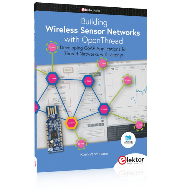
Developing CoAP applications for Thread networks with Zephyr
This book will guide you through the operation of Thread, the setup of a Thread network, and the creation of your own Zephyr-based OpenThread applications to use it. You’ll acquire knowledge on:
The capture of network packets on Thread networks using Wireshark and the nRF Sniffer for 802.15.4.
Network simulation with the OpenThread Network Simulator.
Connecting a Thread network to a non-Thread network using a Thread Border Router.
The basics of Thread networking, including device roles and types, as well as the diverse types of unicast and multicast IPv6 addresses used in a Thread network.
The mechanisms behind network discovery, DNS queries, NAT64, and multicast addresses.
The process of joining a Thread network using network commissioning.
CoAP servers and clients and their OpenThread API.
Service registration and discovery.
Securing CoAP messages with DTLS, using a pre-shared key or X.509 certificates.
Investigating and optimizing a Thread device’s power consumption.
Once you‘ve set up a Thread network with some devices and tried connecting and disconnecting them, you’ll have gained a good insight into the functionality of a Thread network, including its self-healing capabilities. After you’ve experimented with all code examples in this book, you’ll also have gained useful programming experience using the OpenThread API and CoAP.
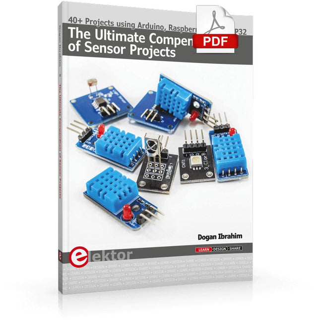
40+ Projects using Arduino, Raspberry Pi and ESP32
This book is about developing projects using the sensor-modules with Arduino Uno, Raspberry Pi and ESP32 microcontroller development systems. More than 40 different sensors types are used in various projects in the book. The book explains in simple terms and with tested and fully working example projects, how to use the sensors in your project. The projects provided in the book include the following:
Changing LED brightness
RGB LEDs
Creating rainbow colours
Magic wand
Silent door alarm
Dark sensor with relay
Secret key
Magic light cup
Decoding commercial IR handsets
Controlling TV channels with IT sensors
Target shooting detector
Shock time duration measurement
Ultrasonic reverse parking
Toggle lights by clapping hands
Playing melody
Measuring magnetic field strength
Joystick musical instrument
Line tracking
Displaying temperature
Temperature ON/OFF control
Mobile phone-based Wi-Fi projects
Mobile phone-based Bluetooth projects
Sending data to the Cloud
The projects have been organized with increasing levels of difficulty. Readers are encouraged to tackle the projects in the order given. A specially prepared sensor kit is available from Elektor. With the help of this hardware, it should be easy and fun to build the projects in this book.
Principles, Systems, and Electronics
This handbook provides a detailed study of the sensors and actuators at the heart of modern vehicle electronics. It begins with basic electrical and electronic concepts, introducing the principles and terminology essential for understanding automotive systems.
The book explores sensors and actuators on a system-by-system basis, including:
Fundamentals of electrical engineering, electromagnetic phenomena, and motor principles
Passive and active electronic components, integrated circuits, protection devices, and automotive-grade electronics
Sensor characteristics, signal conditioning, ADCs, PWM and frequency outputs, and interface adaptation
Automotive communication links and protocols, including LIN and SENT
Engine sensors: air mass, pressure, temperature, speed, position, exhaust and emissions-related sensors
Transmission sensors for manual and automatic systems
Steering and suspension sensors for conventional and active systems
Vehicle body and electrical system sensors for comfort, climate, access, and monitoring functions
Engine actuators such as throttle bodies, injectors, turbo actuators, EGR systems, ignition components, and pumps
Transmission, brake, steering, suspension, and body actuators
Identification and coding of electronic components and packages commonly used in automotive applications
The structure and operating principles of each component are explained, with relevant electronic circuitry illustrated. Its system-oriented organization and practical focus make it a valuable reference for understanding, testing, and troubleshooting automotive electronic systems.
Developing CoAP applications for Thread networks with Zephyr
This book will guide you through the operation of Thread, the setup of a Thread network, and the creation of your own Zephyr-based OpenThread applications to use it. You’ll acquire knowledge on:
The capture of network packets on Thread networks using Wireshark and the nRF Sniffer for 802.15.4.
Network simulation with the OpenThread Network Simulator.
Connecting a Thread network to a non-Thread network using a Thread Border Router.
The basics of Thread networking, including device roles and types, as well as the diverse types of unicast and multicast IPv6 addresses used in a Thread network.
The mechanisms behind network discovery, DNS queries, NAT64, and multicast addresses.
The process of joining a Thread network using network commissioning.
CoAP servers and clients and their OpenThread API.
Service registration and discovery.
Securing CoAP messages with DTLS, using a pre-shared key or X.509 certificates.
Investigating and optimizing a Thread device’s power consumption.
Once you‘ve set up a Thread network with some devices and tried connecting and disconnecting them, you’ll have gained a good insight into the functionality of a Thread network, including its self-healing capabilities. After you’ve experimented with all code examples in this book, you’ll also have gained useful programming experience using the OpenThread API and CoAP.
Mit einem Arduino-Board ohne zusätzliche Sensoren kann man nicht viel anfangen. Dieses Buch richtet sich an jeden, der seinem Arduino-Uno-Board mit Hilfe von zahlreichen Sensoren Leben einhauchen möchte. Wie das geht, zeigt der Autor Schritt für Schritt mit zahlreichen Abbildungen, und das in einer leicht verständlichen Sprache.Damit ein Mikrocontroller wie der Arduino Uno Einfluss auf seine Umwelt nehmen kann, sind Sensoren und Aktoren erforderlich, die von einer Software gesteuert werden. Inzwischen gibt es eine große Auswahl an Sensor-Modulen, die an das Arduino-Board angeschlossen werden können.Als Einstieg in die faszinierende Welt der Sensorik wird in diesem Buch auf das auch bei Elektor erhältliche 37 Module umfassende Sensor-Kit zurückgegriffen. In diesem populären Set sind die Sensoren auf einer kleinen Platine montiert und mit Steckverbindern ausgestattet, was den Anschluss via Breadboard oder Drahtbrücken vereinfacht. Mit den auch für Einsteiger einfach anzuwendenden Sensor-Modulen lassen sich schnell beeindruckende Erfolge erzielen, ohne dass man tief in die Materie der Elektronik eintauchen muss.Die Funktionsweise und Beschaltung der einzelnen Sensoren wird ausführlich erklärt und ihre Verwendung durch die gut dokumentierten Beispielprogramme leicht nachvollziehbar gemacht.
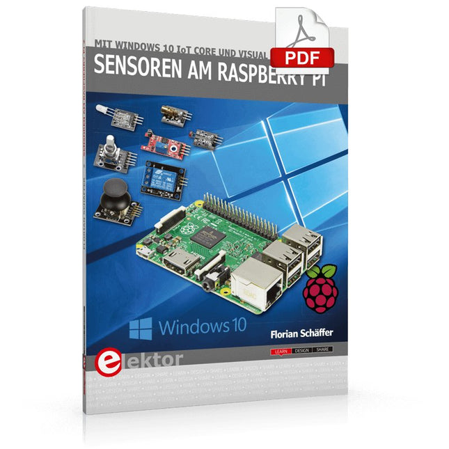
Dieses Buch richtet sich an jeden, der seinen Raspberry Pi mit dem Windows 10 IoT Core betreiben will. Wie das geht, zeigt der Autor mit dem Entwicklungssystem Visual Studio und Visual Basic als Programmiersprache.
Inzwischen gibt es eine große Auswahl an kleinen Sensor-Modulen, die problemlos an den Raspberry Pi angeschlossen werden können – auch wenn sie mitunter für andere Systeme beworben werden, wie etwa für den Arduino. Nicht ohne Grund: Einplatinencomputer sind ohne zusätzliche Peripherie für Elektroniker ziemlich nutzlos. Sie stellen zwar die Rechenleistung und ein Betriebssystem bereit, können aber so gut wie gar nicht mit ihrer Umgebung kommunizieren. Damit ein Computer auch Einfluss auf seine Umwelt nehmen kann, sind Sensoren und Aktoren erforderlich, die von einer Software gesteuert werden, die man selber erstellen kann.
Als Einstieg in die Materie wird in diesem Buch auf das auch bei Elektor erhältliche 37 Module umfassende Sensor-Kit zurückgegriffen. In diesem populären Set sind die Sensoren auf einer kleinen Platine montiert und mit Steckverbindern ausgestattet, was den Anschluss via Breadboard oder Drahtbrücken vereinfacht. Mit den auch für Einsteiger einfach anzuwendenden Sensor-Modulen lassen sich schnell erste Erfolge erzielen, ohne dass man groß in die Materie der Elektronik einsteigen muss.
Die Funktionsweise und Beschaltung der einzelnen Sensoren wird ausführlich erklärt und ihre Verwendung durch die gut dokumentierten Visual Basic-Beispielprogramme leicht nachvollziehbar gemacht.