The Red Pitaya (STEMlab) is a credit card-sized, open-source test and measurement board that can be used to replace most measurement instruments used in electronics laboratories. With a single click, the board can transform into a web-based oscilloscope, spectrum analyser, signal generator, LCR meter, Bode plotter, and microcontroller.
The Red Pitaya (STEMlab) can replace the many pieces of expensive measurement equipment found at professional research organisations and teaching laboratories. The device, that based on Linux, includes an FPGA, digital signal processing (DSP), dual core ARM Cortex processor, signal acquisition and generation circuitry, micro USB socket, microSD card slot, RJ45 socket for Ethernet connection, and USB socket – all powered from an external mains adaptor.
This book is an introduction to electronics. It aims to teach the principles and applications of basic electronics by carrying out real experiments using the Red Pitaya (STEMlab). The book includes many chapters on basic electronics and teaches the theory and use of electronic components including resistors, capacitors, inductors, diodes, transistors, and operational amplifiers in electronic circuits. Many fun and interesting Red Pitaya (STEMlab) experiments are included in the book. The book also makes an introduction to visual programming environment.
The book is written for college level and first year university students studying electrical or electronic engineering.
Die ESP32-S3-BOX-3 basiert auf Espressifs ESP32-S3 Wi-Fi + Bluetooth 5 (LE) SoC mit KI-Beschleunigungsfunktionen. Zusätzlich zu den 512 KB SRAM des ESP32-S3 verfügt die ESP32-S3-BOX-3 über 16 MB Quad Flash und 16 MB Octal PSRAM.
Auf der ESP32-S3-BOX-3 läuft Espressifs eigenes Spracherkennungs-Framework ESP-SR, das dem Anwender einen Offline-KI-Sprachassistenten zur Verfügung stellt. Es bietet Fernfeld-Sprachinteraktion, kontinuierliche Erkennung, Aufwachunterbrechung und die Fähigkeit, über 200 anpassbare Befehlswörter zu erkennen. BOX-3 kann mit Hilfe fortschrittlicher AIGC-Entwicklungsplattformen wie OpenAI auch in einen Online-KI-Chatbot umgewandelt werden.
Basierend auf dem leistungsstarken ESP32-S3 SoC bietet BOX-3 Entwicklern eine sofort einsatzbereite Lösung zur Erstellung von Edge AI- und HMI-Anwendungen. Die fortschrittlichen Funktionen und Möglichkeiten der BOX-3 machen sie zu einer idealen Wahl für diejenigen in der IIoT-Industrie, die sich Industrie 4.0 zu eigen machen und traditionelle Fabrikbetriebssysteme umgestalten wollen.
Die ESP32-S3-BOX-3 ist die Haupteinheit, die durch das ESP32-S3-WROOM-1 Modul betrieben wird, das 2,4 GHz Wi-Fi + Bluetooth 5 (LE) Wireless-Fähigkeit sowie KI-Beschleunigungsfunktionen bietet. Zusätzlich zu den 512 KB SRAM, die vom ESP32-S3 SoC bereitgestellt werden, verfügt das Modul über 16 MB Quad-Flash und 16 MB Octal PSRAM. Das Board ist mit einem 2,4-Zoll-SPI-Touchscreen mit 320 x 240 Pixeln (der "rote Kreis" unterstützt Touch), zwei digitalen Mikrofonen, einem Lautsprecher, einem 3-Achsen-Gyroskop, einem 3-Achsen-Beschleunigungsmesser, einem Typ-C-Anschluss für Stromversorgung und Download/Debug, einem High-Density-PCIe-Anschluss, der Hardware-Erweiterungen ermöglicht, sowie drei Funktionstasten ausgestattet.
Features
ESP32-S3
WiFi + Bluetooth 5 (LE)
Eingebauter 512 KB SRAM
ESP32-S3-WROOM-1
16 MB Quad flash
16 MB Octal PSRAM
Lieferumfang
ESP32-S3-BOX-3 Einheit
ESP32-S3-BOX-3 Sensor
ESP32-S3-BOX-3 Dock
ESP32-S3-BOX-3 Halterung
ESP32-S3-BOX-3 Bread
RGB-LED-Modul und Dupont-Kabel
USB-C Kabel
Downloads
GitHub
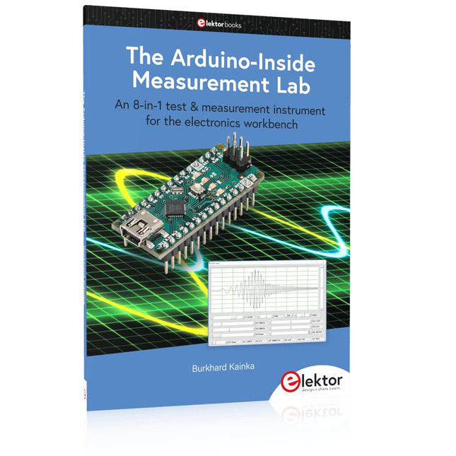
An 8-in-1 test & measurement instrument for the electronics workbench
A well-equipped electronics lab is crammed with power supplies, measuring devices, test equipment and signal generators. Wouldn‘t it be better to have one compact device for almost all tasks? Based on the Arduino, a PC interface is to be developed that’s as versatile as possible for measurement and control. It simply hangs on a USB cable and – depending on the software – forms the measuring head of a digital voltmeter or PC oscilloscope, a signal generator, an adjustable voltage source, a frequency counter, an ohmmeter, a capacitance meter, a characteristic curve recorder, and much more.
The circuits and methods collected here are not only relevant for exactly these tasks in the "MSR" electronics lab, but many details can also be used within completely different contexts.
Wenn Sie bohren müssen, empfehlen wir, auf FR1-Substraten zu bohren.
Im Gegensatz zu FR4 enthält der Staub von FR1 kein Fiberglas. Es ist auch ein weicheres Material, was bedeutet, dass die Bohrer weniger verschleißen.
Laden Sie die Vorlage herunter und integrieren Sie sie in Ihr Design hier.
10 Substrate enthalten.
This book is intended as a highly-practical guide for Hobbyists, Engineers and Scientists wishing to build measurement and control systems to be controlled by a local or remote Personal Computer running the Linux operating system. Both hardware and software aspects of designing typical embedded systems are covered in detail with schematics, code listings and full descriptions. Numerous examples have been designed to show clearly how straightforward it can be to create the interfaces between digital and analog electronics, with programming techniques for creating control software for both local and remote systems. Hardware developers will appreciate the variety of circuits, including a novel, low cost modulated wireless link and will discover how using Matlab® overcomes the need for specialist programming skills.
Software developers will appreciate how a better understanding of circuits plus the freedom offered by Linux to directly control at the register level enables them to optimize related programs. There is no need to buy special equipment or expensive software tools in order to create embedded projects covered in this book. You can build such quality systems quickly using popular low-cost electronic components and free distributed or low-cost software tools. Some knowledge of basic electronics plus the very basics of C programming only is required.
Many projects in this book are developed using Matlab® being a very popular worldwide computational tool for research in engineering and science. The book provides a detailed description of how to combine the power of Matlab® with practical electronics.
With an emphasis on learning by doing, readers are encouraged by examples to program with ease; the book provides clear guidelines as to the appropriate programming techniques “on the fly”. Complete and well-documented source code is provided for all projects.
If you want to learn how to quickly build Linux-based applications able to collect, process and display data on a PC from various analog and digital sensors, how to control circuitry attached to a computer, then even how to pass data via a network or control your embedded system wirelessly and more – then this is the book for you!
Features of this Book
Use the power, flexibility and control offered only by a Linux operating system on a PC.
Use a free, distributed downloadable GNU C compiler Use (optional) a low-cost Student Version of Matlab®.
Use low-cost electronic sub-assemblies for projects.
Improve your skills in electronics, programming, networking and wireless design.
A full chapter is dedicated to controlling your sound card for audio input and output purposes.
Program sound using OSS and ALSA.
Learn how to combine electronic circuits, software, networks and wireless technologies in the complete embedded system.
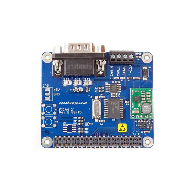
This PiCAN 2 board provides CAN-Bus capability for the Raspberry Pi 2/3. It uses the Microchip MCP2515 CAN controller with MCP2551 CAN transceiver. Connection are made via DB9 or 3-way screw terminal. This board includes a switch mode power suppler that powers the Raspberry Pi is well.
Easy to install SocketCAN driver. Programming can be done in C or Python.
Not suitable for Raspberry Pi 4, please use PiCAN 3 instead.
Features
CAN v2.0B at 1 Mb/s
High speed SPI Interface (10 MHz)
Standard and extended data and remote frames
CAN connection via standard 9-way sub-D connector or screw terminal
Compatible with OBDII cable
Solder bridge to set different configuration for DB9 connector
120Ω terminator ready
Serial LCD ready
LED indicator
Foot print for two mini push buttons
Four fixing holes, comply with Pi Hat standard
SocketCAN driver, appears as can0 to application
Interrupt RX on GPIO25
5 V/1 A SMPS to power Raspberry Pi and accessories from DB9 or screw terminal
Reverse polarity protection
High efficiency switch mode design
6-20 V input range
Optional fixing screws – select at bottom of this webpage
Downloads
User guide
Schematic Rev B
Writing your own program in Python
Python3 examples in Github
Das PeakTech 1265 ist ein preisgünstiges 30 MHz 2-Kanal Digital-Speicheroszilloskop mit hochauflösendem TFT-Farbdisplay und umfassenden Zusatzfunktionen. Es verfügt über eine Abtastrate von bis zu 250 MS/s und überzeugt durch seine hohe Qualität und einfache Handhabung bei bestem Preis-/Leistungsverhältnis. Für die schnelle Darstellung jeder eingehenden Wellenform reicht ein Druck auf die Autoset-Taste, schon sucht das Oszilloskop selbst die bestmögliche Anzeige. Mit Autoscale hingegen, lässt sich die Skalierung der Zeitbasis anwenderfreundlich anpassen. Für die Darstellung der Oszilloskopanzeige an einem externen Monitor oder Beamer, verfügt dieses Oszilloskop über einen VGA-Ausgang.
Features
2-Kanal Oszilloskop mit 30 MHz analoger Bandbreite bei max. 250 MS/s Abtastrate
20 cm (8“) TFT-Farbdisplay mit 800 x 600 Bildpunkten
LAN und USB-Device Anschluss zur Echtzeit-Datenübertragung
USB-Host Anschluss für externe USB-Datenträger VGA-Schnittstelle zum Anschluss externer Wiedergabegeräte
Handliches und flaches Gehäusedesign mit Tragegriff
Autoset-Funktion zur benutzerfreundlichen Bedienung
Aufzeichnungslänge von max. 10.000 Punkten
Automatische Messmodi, XY-Modus und FFT-Funktion
Technische Daten
Bandbreite
30 MHz
Kanäle
2
Bilddiagonale (TFT)
20 cm (8")
Auflösung
800 x 600 Pixel
Display-Typ
Farb-TFT
Sampling 1 CH
250 MS/s
Sampling 2 CH
125 MS/s
Hor. Skala max.
100 s/div
Hor. Skala min.
5 ns/div
Speichertiefe
10.000 Punkte
Anstiegszeit
Vert. Auflösung
8 Bit
Vert. Skala max.
10 V/div
Vert. Skala min.
2 mV/div
Schnittstellen
1x USB, 1x LAN, 1x VGA
Netzspannung
110/240 V AC; 50/60 Hz
Lieferumfang
PeakTech 1265 Oszilloskop
USB-Kabel
Software-CD für Windows
Netzkabel
2 Tastköpfe
BNC-Kabel
Bedienungsanleitung
Downloads
Software
Datenblatt
Offizielles Gehäuse für Raspberry Pi 3 B(+), 2 und B+ (schwarz/grau)
High-quality ABS construction
Removable side panels and lid for easy access to GPIO, camera and display connectors
Light pipes for power and activity LEDs
Extraordinarily handsome
Colour: black/grey
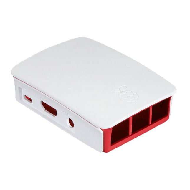
Offizielles Gehäuse für Raspberry Pi 3 B(+), 2 und B+ (weiß/rot)
High-quality ABS construction
Removable side panels and lid for easy access to GPIO, camera and display connectors
Light pipes for power and activity LEDs
Extraordinarily handsome
Colour: White/red
Der JOY-iT JDS2960 ist ein 2-Kanal Signalgenerator, der Signale mit bis zu 60 MHz erzeugen kann. Sein kompaktes Design und die Möglichkeit, es mit einer Powerbank zu betreiben, machen es ideal für den mobilen Einsatz.
Mit einer Vielzahl von Wellenformen, darunter Sinus, Rechteck, Dreieck, Impuls, Halbwelle und mehr, eignet es sich für verschiedene Anwendungen in der Messtechnik.
Zusätzlich verfügt der JDS2960 über eine 1-Kanal-Frequenzzuteilung. Seine hohe Frequenzgenauigkeit von ±20 ppm und eine Stabilität von ±1 ppm/3 h sorgen für eine hervorragende Signalqualität und große Flexibilität.
Das 2,4 Zoll große TFT-Farbdisplay sorgt für eine benutzerfreundliche Bedienung und ermöglicht vielfältige Einsatzmöglichkeiten.
Features
2 Kanäle
Bis zu 60 MHz
Robustes Aluminium-Gehäuse
1-Kanal Frequenzzähler
Bis zu 20 Vpp
Viele verschiedene vorprogrammierte Wellenformen und bis zu 60 benutzerdefinierte Wellenformen
Pulsfunktion
Technische Daten
Kanäle
2-Kanal Signalgenerator1-Kanal Frequenzzähler
Frequenzbereich
Sinus: 0-60 MHzQuadrat, Dreieck: 0-25 MHzTTL, Impuls: 0-6 MHz
Signalformen
Sinus, Rechteck, Dreieck, Impuls, halbe/durchgezogene Welle, exponentieller Anstieg/Abfall usw.
Messbereichs-Frequenzzähler
1-100 MHz
Frequenzgenauigkeit
±20 ppm
Frequenzstabilität
±1 ppm/3 h
Abtastrate
266 MSa/s
Display
2,4" TFT-Farb-LCD
Vertikale Wellenauflösung
14 Bit
Amplitudenbereich
<10 MHz: 0-20 Vpp>10 MHz: 0-10 Vpp
Amplitudenauflösung
1 mV
Amplitudenstabilität
±5%/5h
Amplitudenflachheit
<10 MHz: ±5%>10 MHz: ±10%
Impedanz der Ausgabe
50 Ω ±10%
Verzerrungsfaktor
<0,8% (20 Hz-20 KHz, 0 dBm)
Abmessungen
145 x 95 x 55 mm
Gewicht
900 g
Lieferumfang
1x JOY-iT JDS2960 Signalgenerator
1x Netzteil
1x BNC-BNC-Kabel
2x BNC-Krokodilklemmen-Kabel
1x USB-DC-Stromkabel
1x USB-Datenkabel
Downloads
Datenblatt
Handbuch
Software