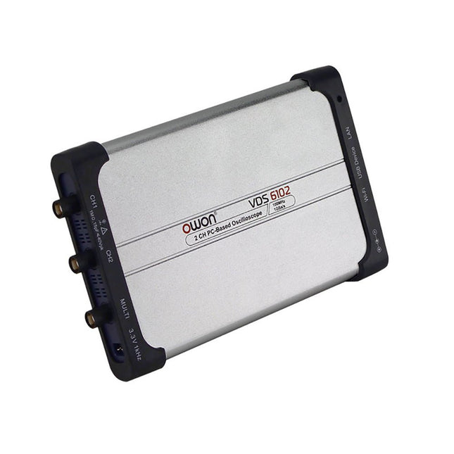
OWON VDS1022I 2-Kanal USB-Oszilloskop (25 MHz) ist ein Oszilloskop für die Verwendung mit einem Computer. Es wird über USB mit Strom versorgt und hat eine kleine Größe, was es leicht macht, es mitzunehmen. Das Oszilloskop ist sehr wirtschaftlich. Es verfügt über eine abgeschirmte USB-Verbindung, die Störungen reduziert und den Computer vor Überspannung schützt. Der Mehrfachport am Oszilloskop kann für externes Triggern, Triggerausgabe oder Pass/Fail-Ausgabe verwendet werden. Features 25 MHz Bandbreite und maximale Echtzeit-Abtastrate von 1 GS/s 10 Mio. Aufzeichnungslänge Benutzerfreundliche Oberfläche: FFT, X-Y und Wellenform-2-Ansichten werden auf demselben Bildschirm angezeigt Mehrere Triggeroptionen: Flanke, Video, Steigung, Puls und Alternativ USB-Isolierung - weniger Signalstörungen, mehr PC-Schutz USB-Bus-Stromversorgung und LAN-Fernsteuerung (optional) Ultra flaches Gehäusedesign für einfache Transportierbarkeit. Technische Daten Bandbreite 25 MHz Kanal 2+1 (mehrfach) Abtastrate 100 MSa/s Horizontale Skala (s/div) 5 ns/div~100s/div, Schrittweite 1~2~5 Datensatzlänge 5K Max. Eingangsspannung 400 V (PK - PK) (DC+AC, PK - PK) 40 V (PK - PK) (DC+AC, PK - PK) Vertikale Auflösung (A/D) 8 Bit (2 Kanäle gleichzeitig) Modell VDS1022I Vertikale Empfindlichkeit 5 mV/div~5 V/div Triggertyp Flanken-, Impuls-, Video-, Steilheits- und Wechselauslösung Auslösemodus Auto, Normal und Einzeln Aufnahmemodus Stichprobe, Spitzenwert-Erkennung und Durchschnitt Wellenform Mathematik +, -, ×, ÷, invertieren, FFT Kommunikationsschnittstelle USB 2.0 (Isolierung) Multifunktion Schnittstelle Signaltyp Pegel Standard TTL Stromversorgung 5,0 V/1 A Leistungsaufnahme ≤2,5 W Abmessungen (B × H × T) 170 x 120 x 18 mm Gewicht 0,26 kg Lieferumfang 1x OWON VDS1022I Oszilloskop 1x CD-ROM 1x Schnellstartanleitung 2x Oszilloskop-Tastkopf 1x Tastkopfwerkzeug 1x Netzteil 1x USB-Kabel 1x Silikonhüllen-Schutz 1x Stromkabel Downloads Datenblatt Benutzerhandbuch SCPI-Protokoll USB-Driver
The OWON VDS6000 Series PC Oscilloscope combines powerful performance with a sleek, ultra-thin design. With 100 MHz bandwidth, 1 GSa/s real-time sampling, and up to 14-bit resolution, it delivers highly accurate measurements. The built-in 5 MHz function generator, USB-C power supply, and optional WiFi connectivity make it incredibly versatile.
Compatible with Windows, Linux, Android, and iOS, the VDS6000 is perfect for labs, fieldwork, and remote diagnostics – compact, flexible, and ready for any challenge.
Features
Bandwidth: 100 MHz
Vertical resolution: 14 bits
Rise time: ≤3.5 ns
Memory: 10 Mpts
Number of channels: 2 channels + 1 channel function generator
Horizontal scale: 5ns - 100s/div
Sample rate: Max. 1 GSa/s
Maximum voltage: 40 V (peak - peak)
Automatic measurements: Vpp, Vavg, Vamp, Vrms, Freq, Period, Vmax, Vmin, Vtop, Vbase, Overshoot, Preshoot, Rise Time,
Connectivity: USB-C, LAN, Wifi (optional)
Fall Time, Delay A→B↑, Delay A→B↓, +Width, -Width, +Duty, -Duty
Bandwidth: 5 MHz
Sample rate: 25 MSa/s
Standard waveforms: Sine (0.1 Hz - 5 MHz), Square (0.1 Hz - 200 kHz), Ramp (1 Hz - 10 kHz), Pulse (1 Hz - 10 kHz)
Resolution: 10 bits
DC offset range (AC + DC): ±2.5 V
Amplitude range: 10 mVpp - 5 Vpp
Dimensions: 190 x 120 x 18 mm
Weight: 380 g
Downloads
Manual
Quick Guide
PC Software
MacOS Software
Bandbreite
100 MHz
Beispielrate
100 MS/s
Horizontale Skalierung (s/div)
5ns/div - 1000s/div, Schritte von 1 - 2 - 5
Kanal
4
Anzeige
7-Zoll-Farb-LCD, 800 x 480 Pixel
Eingangskopplung
DC, AC und GND
Vertikale Auflösung (A/D)
Vertikale Auflösung (A/D)
Vertikale Empfindlichkeit
5 mV/Div – 5 V/Div (am Eingang)
Trigger-Typ
Kante, Video
Trigger-Modus
Auto, Normal und Einzeln
Wellenformmathematik
+, -, x, ÷, invertieren, FFT
Sicherung
2 A, T-Klasse, 250 V
Abmessungen (B x H x T)
301 mm x 152 mm x 70 mm
Gewicht
1,1 kg
Inbegriffen
1 x SDS1104 1 x Netzkabel
1 x CD-ROM
1 x Kurzanleitung
1 x USB-Kabel
4 x Oszilloskop-Sonde
1 x Sondeneinstellung
Weitere Informationen finden Sie hier im Benutzerhandbuch.
Der HDS242 ist ein tragbares 2-in-1-Multifunktionsmessgerät, das als 2-Kanal-Oszilloskop und Multimeter verwendet werden kann. Es verfügt über ein kontrastreiches 3,5-Zoll-Farbdisplay und eignet sich für die Wartung von Außenanlagen, schnelle Vor-Ort-Messungen, die Wartung von Kraftfahrzeugen, die Erkennung von Energie usw.FeaturesOszilloskop + MultimeterHochauflösendes, kontrastreiches 3,5-Zoll-LCD-Farbdisplay – für den Außeneinsatz geeignet18650 Lithium Batterie – bis zu 6 Stunden Dauerbetrieb möglichUSB Typ-C-Schnittstelle – unterstützt Powerbank und PC-VerbindungSelbst-KalibrierungsfunktionSCPI unterstützt für sekundäre EntwicklungTechnische DatenOszilloskopBandbreite40 MHzKanäle2-Kanal-OszilloskopAbtastrate250 MSa/sAkquisitionsmodellNormal, Spitzenwert erkennenDatensatzlänge8KAnzeigen3,5-Zoll-LCDWellenform-Aktualisierungsrate10.000 wfrms/sEingangskopplungDC, AC und ErdeEingangsimpedanz1 MΩ ±2%, parallel zu 16 pF ±10 pFSondendämpfungsfaktoren1X, 10X, 100X, 1000X, 10000XMax. Eingangsspannung400 V (DC+AC, PK-PK, 1 MΩ Eingangsimpedanz) (10:1 Sondendämpfung)Bandbreitenbegrenzung (typisch)20 MHzHorizontale Skala5 ns/div - 1000 s/div, schrittweise 1 - 2 - 52 ns/div - 1000 s/div, schrittweise 1 - 2 - 55 ns/div - 1000 s/div, schrittweise um 1 - 2 - 52ns/div - 1000s/div, schrittweise um 1 - 2 - 5Vertikale Empfindlichkeit10 mV/div - 10 V/divVertikale Auflösung8 BitTriggertypRandTrigger-ModiAuto, Normal, EinzelAutomatische MessungFrequenz, Periode, Amplitude, Max, Min, Mittelwert, PK-PKCursor-MessungΔV, ΔT, ΔT & ΔV zwischen CursornMultimeterMax. Auflösung20.000 CountsTestmodusSpannungs-, Strom-, Widerstands-, Kapazitäts-, Dioden- und DurchgangsprüfungEingangsimpedanz10 MΩMax. EingangsspannungWechselspannung: 750 V | Gleichstrom: 1000 VMax. EingangsstromGleichstrom: 10 A | Wechselstrom: 10 ADiode0-2 VAndereKonnektivitätUSB-CAbmessungen198 x 96 x 38 mmGewicht600 g (ohne Batterien)Lieferumfang1x OWON HDS242 Oszilloskop1x Tasche1x Tastkopf1x Netzkabel1x Tastkopfjustierung1x USB-Kabel1x Netzadapter1x Paar Sondenkabel für Multimeter (rot und schwarz)1x Paar Oszilloskop-Tastkopfkabel (BNC auf Krokodilklemme)1x Benutzerhandbuch (Englisch)DownloadsUser Manual für HDS200 Serie (Deutsch)SCPI Protocol for HDS200 SeriesQuick Guide for HDS200 SeriesPC Software for OWON HDS200 Series
UNI-T UPO1202CS ist ein multifunktionales, kostengünstiges 2-Kanal-Digital-Phosphor-Oszilloskop mit 200 MHz Bandbreite und 1 GSa/s Abtastrate. Es kann in großem Umfang in den Bereichen elektronisches und elektrisches Design, Debugging, Bildung und Industriedesign eingesetzt werden. Die UPO1000CS-Serie nutzt parallele digitale Signalverarbeitungstechnologie, die die Datenverarbeitungsgeschwindigkeit und die Wellenformerfassungsrate erheblich verbessert. Die ursprüngliche Ultra Phosphor-Technologie kann den kumulativen Effekt des getesteten Signals als vielschichtiges Nachleuchten darstellen. Im Vergleich zu herkömmlichen digitalen Speicheroszilloskopen können digitale Phosphor-Oszilloskope dreidimensionale Wellenformdaten zu Amplitude, Zeit und Signalintensität darstellen. Die Fast Acquire-Technologie kann ungewöhnliche Ereignisse wie Video, Jitter, Rauschen und Runt-Signale genau erfassen. Technische Daten UPO1102CS UPO1202CS Bandbreite 100 MHz 200 MHz Analoge Kanäle 2 2 Abtastrate 1 GSa/s 1 GSa/s Speichertiefe 56 Mpts pro Kanal 56 Mpts pro Kanal Anstiegszeit ≤3,5ns ≤1,8ns Erfassungsrate 500.000 wfms/s 500.000 wfms/s Wellenform-Aufzeichnung 100.000 Bilder 100.000 Bilder Features 7' WVGA (800 x 480) TFT-LCD Ultra-Phosphor-Superfluoreszenz-Display-Effekt, bis zu 256 Graustufen der Anzeige Unterstützt RS232-, I²C-, SPI-, CAN- und LIN-Trigger Innovative RS232-, I²C-, SPI-, CAN- und LIN-Hardware-Dekodierung Vertikale Skala: 1 mV/Teilung-20 V/Teilung Geringes Hintergrundrauschen: Erweiterte FFT-Funktion mit 1M Punkten. Unterstützt Frequenzeinstellung, Wasserfalldiagramm, Erkennungseinstellung und Marker-Messung etc. 36 Arten von Wellenformparametern können automatisch gemessen werden Umfangreiche Triggerfunktionen (Flanke, Pulsbreite, Video, Steigung, Lauf, Überschwingen, Verzögerung, Timeout, Dauer, Setup und Hold, Nth Edge und Pattern Trigger) Multi-Scopes unterstützen unabhängige Zweikanal-Trigger-Fluoreszenzanzeige Unabhängiger 7-Bit-Hardware-Frequenzzähler mit mehreren Kanälen DVM unterstützt unabhängige Zweikanal-AC- und DC-Echt-Effektivwertmessungen Arithmetische Funktionen für Wellenformen (FFT, +, -, ×, ÷, digitale Filterung, logische Operationen und erweiterte Operationen) Umfangreiche Schnittstellen: USB-Host, USB-Gerät, LAN, EXT Trig, AUX Out (Trig Out, Pass/Fail) Unterstützt SCPI-programmierbare Instrumenten-Standardbefehle Unterstützung von WEB-Zugang und Steuerung Downloads Datasheet Programming Manual User's Manual Quick Start Guide Software
SmartScope ist ein kompaktes 2-Kanal USB-Oszilloskop mit einer Bandbreite von 30 MHz und einer Abtastrate von 2x 100 MSa/s. Es ist kompatibel mit allen gängigen Plattformen, einschließlich Windows, macOS, Linux und Android. Die Bedienung und Anzeige der Messsignale erfolgt über Smartphone, Tablet oder PC. Darüber hinaus sind ein Logik Analyzer und ein Signalgenerator integriert.
Bleiben Sie mobil: Dank der Einkabellösung haben Sie SmartScope immer dabei! Die intuitive Gestensteuerung (tippen, zoomen und wischen) ersetzt die altmodischen Oszilloskop-Bedienelemente.
Und es kann noch mehr: Entwickeln Sie Ihre digitalen Schnittstellen mit dem Logic Analyzer (100 MS/s)! Entwerfen Sie jede gewünschte Signalform mit Excel und legen Sie sie im integrierten Speicher des Arbitrary Waveform Generator (AWG) ab! Zeigt die momentane Spannung an jedem beliebigen Punkt Ihrer Schaltung bis zu 100 Millionen Mal pro Sekunde an.
Die Software unterstützt Windows / Linux / macOS sowie Android und Export-Formate (Excel .csv / Matlab .mat).
Features
Jeder Kanal wird mit 100 MHz/s abgetastet.
AC/DC-Kopplung an Analogeingängen
100% geräuschlos
64 Mbit RAM: 10000-fache Vergrößerung
Arbiträrer Wellenformgenerator
8 digitale Eingänge mit je 100 MS/s
4 digitale Ausgänge mit je 100 MS/s
Externe Stromversorgung des Oszilloskops für den Fall, dass Ihr Mobiltelefon keinen Strom liefern kann.
Technische Daten
Oszilloskop
Bandbreite
30 MHz (-3 dB point)
Abtastrate
2x 100 MS/s
Kanäle
2
Max. Pre-Trigger-Position
16x Vollwert
Max. Post-Trigger-Position
Vollwert
Max. volle Spannungsskala
10 V/div (±35 V Eingangsbereich)
Min. volle Spannungsskala
20 mV/div
Analogeingangsbereich
-35 V, +35 V
Max. Eingang Peak-to-Peak
40 V
Signalkopplung
AC / DC
Präzision
8 bit
Eingangsimpedanz
1 MΩ // 10 pF
Wellenformen
200 Wellenformen/s
Datenverzögerung zum Host
<10 ms
Sample-Tiefe
Bis zu 4 Millionen Samples pro Kanal
Externer Auslöser
Ja
Logic Analyzer
Eingangskanäle
8
Eingangsimpedanz
100 kOhm // 2 pF zu GND
Abtastrate
100 MS/s
Logikebene
1,8 V bis 5,0 V
Diodenschutz
Bidirektional
Eingangsdatenpuffer
4 Millionen Samples
Wellenformen
200 Wellenformen/s
Datenverzögerung zum Host
<10 ms
Protokoll-Decoder
I²C, SPI, UART, I²S integriert Benutzer erweiterbar
Signalgenerator (Analoger Ausgang)
Ausgangskanäle
1
Datenrate
Bis zu 50 MS/s
Ausgangspegel
0-3,3 V (Operationsverstärker angesteuert)
Ausgangspuffer
Bis zu 2048 Samples
Max. Anstiegsgeschwindigkeit
30 ns/V
Schritt
13 mV
Signalgenerator (Digitaler Ausgang)
Kanäle
4
Datenrate
Bis zu 100 MS/s
Ausgangspegel
3,3 V oder 5 V (wählbar)
Ausgangspuffer
Bis zu 2048 Samples
Diodenschutz
Ja
Programmierbare Logik
USB-Controller
MicroChip PIC18F14K50
USB-Interface
PicKit3 oder USB-programmierbar
FPGA
Xilinx Spartan 6
FPGA-Interface
JTAG und USB-programmierbar
Abmessungen & Gewicht
Abmessungen
110 x 64 x 24,2 mm (L x B x T)
Gewicht
158 g
Gehäuse
Aluminium
Konnektivität
Gerät/Host
mini-USB (inbegriffen)
Wellenformen aufnehmen
Matlab (.mat) oder Excel (.csv) Dateien in Dropbox speichern
Analog
BNC 2 Tastköpfe (inbegriffen)
Digital
8x 0.1" Pitch, Tastköpfe (inbegriffen)
Synchronisierung
USB micro B-B
Stromversorgung
USB micro B (optional)
Lieferumfang
1x SmartScope USB-Oszilloskop
2x Analoger Tastkopf
1x Digitales Tastkopfkabel
1x USB-Kabel
Downloads
Software
GitHub
Wiki
Die Freihandsonden der SQ-Serie von Sensepeek haben einen niedrigeren Schwerpunkt, was sie im Vergleich zur ursprünglichen Freihandsonde der SP-Serie noch stabiler macht. Alle Sonden der SQ-Serie sind außerdem isoliert und können wie jede herkömmliche Sonde in der Hand verwendet werden, ihr volles Potenzial wird jedoch bei freihändigen Messungen genutzt.
Die Oszilloskopsonden der SQ-Serie umfassen außerdem mehr Erdungsoptionen, verfügen über einen Sondenspitzenschutz, ein längeres Kabel und unterstützen Oszilloskope mit automatischer Skalierung (10:1).
Alle beliebten Funktionen der freihändigen Messung, der austauschbaren Prüfnadel mit feiner Gewindespitze und der farbcodierten Kabelhalter sowie des minimalistischen Designs bleiben erhalten und machen herkömmliche Handsonden überflüssig.
Sowohl Länge als auch Gewicht der SQ-Sonden sind perfekt ausbalanciert für die Verwendung mit PCBite-PCB-Haltern und Grundplatten, die für die Freisprechfunktion unerlässlich sind.
Features
Passiver 10:1-Tastkopf mit Unterstützung für Oszilloskope mit automatischer Skalierung
Gefederte Prüfnadel für Feinabstandsmessungen
Mehrere Bodenoptionen
Farbcodierte Kabelhalter
Schutz der Sondenspitze
Isoliert, kann in der Hand verwendet werden
Verbesserter Sondenhalter für freihändige Messungen bei Verwendung mit PCBite-Leiterplattenhaltern
Lieferumfang
1x SQ350 350 MHz Sonde mit federnder Prüfnadel
1x SQ-Sondenhalter für freihändige Messungen
1x Prüfhaken mit abnehmbaren Kabeln (5 cm und 10 cm) für bequemen Erdungsanschluss
1x Krokodilkabel für bequemen Erdungsanschluss
1x Standard-Erdungsfeder für Handmessungen bei Nennbandbreite
1x Einzigartige Erdungsfeder für völlig freihändige Messungen bei Nennbandbreite
1x Set farbcodierte Kabelhalter (4 Farben)
1x Tastspitzenschutz
1x Zusätzliche Prüfnadel
Downloads
Benutzerhandbuch SQXX0 Rev1.1
,
von Clemens Valens
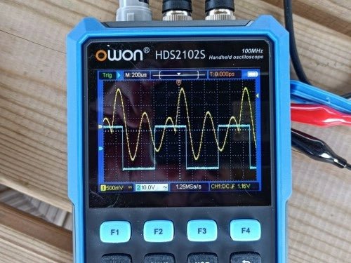
Review: Owon HDS2102S Handheld 2-Kanal 100-MHz-Oszilloskop, Multimeter & Signalgenerator
[Gesponsert] Das Owon HDS2102S ist ein Handgerät, das ein Zwei-Kanal-Oszilloskop, ein Multimeter und einen Arbiträr-/Signalgenerator in sich vereint. Das Oszilloskop hat eine Bandbreite von 100...