
Suchergebnisse für "iic OR i2c OR serial OR interface OR adapter OR module"
-

Elektor Bundles Build Smart Projects with the XIAO ESP32-C3 Board (Bundle)
Dieses Bundle enthält alles, was Sie brauchen, um direkt mit dem XIAO ESP32-C3 Development Board loszulegen. Lernen Sie die Grundlagen des ESP32-C3 kennen und entwickeln Sie praktische Projekte mit Wi-Fi, Bluetooth, Sensoren, Displays, PWM, Deep Sleep und vielem mehr. Buch: Build Smart Projects with the XIAO ESP32-C3 Board Das XIAO ESP32-C3 Board kombiniert den ultrakompakten Formfaktor der XIAO-Serie mit den umfangreichen Funktionen des ESP32-C3-Chips, einschließlich integriertem Wi-Fi und Bluetooth 5.0. Dieses Buch ist ein umfassender, praxisorientierter Leitfaden, mit dem Sie das Potenzial dieses leistungsstarken und dennoch preisgünstigen Development Boards voll ausschöpfen können. Der Autor führt die Leser von den Grundlagen bis hin zu fortgeschrittenen Projekten. Angefangen beim Blinken und Dimmen von LEDs geht es weiter mit ADC und PWM für die präzise Anbindung von Sensoren und PWM-gesteuerte Lichteffekte, bevor praktische Anwendungen aus der realen Welt umgesetzt werden, darunter: Eine Wi-Fi-Wetterstation mit OLED-Display und aktuellen Online-Wetterdaten Ein Ultraschall-Einparkassistent mit akustischer Rückmeldung Eine Kühlschrank-Messsonde mit Klimasensoren und Deep Sleep für jahrelangen Batteriebetrieb Ein Retro-Pong-Spiel, das berührungslos per Sensor gesteuert wird Eine mikrofonbasierte Party-App, die auf Klatschen reagiert Und vieles mehr: Lichtsteuerung, Reaktionszeitmessung, Netzfrequenzanalyse, Bodenfeuchtemessung, LED-Ambientebeleuchtung und 7-Segment-Anzeigen Seeed Studio XIAO ESP32C3 Das Seeed Studio XIAO ESP32C3 ist mit einem hochintegrierten ESP32-C3-Chip ausgestattet, der auf einem 32-Bit-RISC-V-Prozessor mit vierstufiger Pipeline basiert und mit bis zu 160 MHz arbeitet. Das Board verfügt über ein hochintegriertes ESP32-C3-SoC. Der Chip ist mit einem vollständigen 2,4-GHz-Wi-Fi-Subsystem ausgestattet und unterstützt damit den Station-Modus, SoftAP-Modus, SoftAP-&-Station-Modus sowie den Promiscuous-Modus für unterschiedliche Wi-Fi-Anwendungen. Gleichzeitig arbeitet er äußerst energieeffizient und unterstützt Bluetooth 5 sowie Bluetooth Mesh. Mit 400 KB SRAM und 4 MB Flash bietet der Chip ausreichend Speicherplatz für Programme und eröffnet zahlreiche Möglichkeiten für IoT-Steuerungsanwendungen. Anwendungen Internet der Dinge (IoT) Wearables Gesundheitsüberwachung Bildung Energiesparende Netzwerke Schnelle Prototypenentwicklung Technische Daten Processor ESP32-C3 SoC RISC-V single-core 32-bit chip processor with a four-stage pipeline that operates at up to 160 MHz Wireless Complete 2.4GHz Wi-Fi subsystem Bluetooth Low Energy 5.0/ Bluetooth Mesh On-chip Memory 400 KB SRAM & 4 MB Flash Interface 1x UART, 1x I²C, 1x SPI, 11x GPIO (PWM), 4x ADC 1x Reset button, 1x Boot button Power (Typ.) Max 3.3 V Output Current: 500 mA Test Condition: BAT Pin Input @ 3.8 V Source Capability: 3 A Charging current: 380 mA(Fast) / 40 mA(Trickle) Input voltage (VIN): 5 VInput voltage (BAT): 3.7 V Deep Sleep Power Consumption Deep Sleep Mode: 44 μA Wi-Fi Enabled Power Consumption Active Mode: 75 mA Modem-sleep Mode: 25 mA Light-sleep Mode: 4 mA BLE Enabled Power Consumption Modem-sleep Mode: 27 mA Light-sleep Mode: 10 mA Dimensions 21 x 17.8 mm Lieferumfang 1x Seeed Studio XIAO ESP32C3 1x Antenne 2x 7-Pin-Header Downloads Wiki Datasheet Dieses Bundle enthält: Buch: Build Smart Projects with the XIAO ESP32-C3 Board (Einzelpreis: 35 €) Board: Seeed Studio XIAO ESP32C3 (Einzelpreis: 10 €)
€ 44,95€ 39,95Bestpreis
-
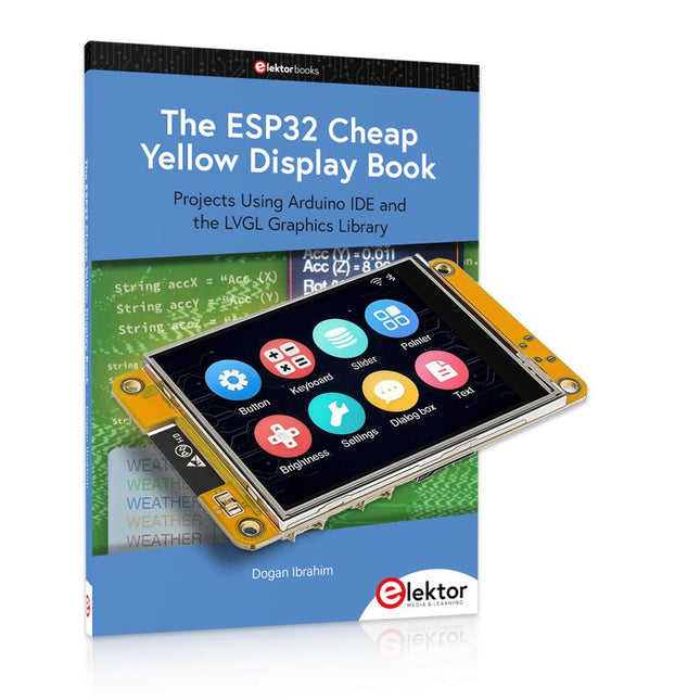
Elektor Bundles The ESP32 Cheap Yellow Display Bundle
Über 40 vollständig getestete ESP32-Projekte mit Arduino IDE und der LVGL-Grafikbibliothek Dieses Bundle enthält das ESP32 Cheap Yellow Display (CYD) – ein kompaktes Entwicklungsboard, das einen Standard-ESP32-Mikrocontroller mit einem 320 x 240 Pixel großen TFT-Farbdisplay kombiniert. Das Board verfügt außerdem über mehrere Anschlüsse für GPIO, serielle Kommunikation (TX/RX), Strom und Masse. Das integrierte Display ist ein großer Vorteil und ermöglicht die Erstellung komplexer, grafikbasierter Projekte ohne externe LCDs oder Displays. Das Begleitbuch stellt die Hardware und die integrierten Anschlüsse des CYD-Boards detailliert vor. Es bietet eine Reihe von Projekten für Anfänger und Fortgeschrittene, die mit der beliebten Arduino IDE 2.0 entwickelt wurden. Sowohl grundlegende Grafikfunktionen als auch die leistungsstarke LVGL-Grafikbibliothek werden behandelt, und praktische Projekte veranschaulichen jeden Ansatz. Alle enthaltenen Projekte wurden vollständig getestet und sind sofort einsatzbereit. Das Buch enthält Blockdiagramme, Schaltpläne, vollständige Codelisten und Schritt-für-Schritt-Erklärungen. Mit der LVGL-Bibliothek können Leser moderne, vollfarbige grafische Benutzeroberflächen mit Widgets wie Schaltflächen, Beschriftungen, Schiebereglern, Kalendern, Tastaturen, Diagrammen, Tabellen, Menüs, Animationen und mehr erstellen. ESP32 Cheap Yellow Display Board Dieses Entwicklungsboard (auch bekannt als "Cheap Yellow Display") wird vom ESP-WROOM-32 angetrieben, einem Dual-Core-MCU mit integrierten Wi-Fi- und Bluetooth-Funktionen. Es arbeitet mit einer Hauptfrequenz von bis zu 240 MHz, mit 520 KB SRAM, 448 KB ROM und einem 4 MB Flash-Speicher. Das Board verfügt über ein 2,8" Display mit einer Auflösung von 240x320 und Resistive Touch. Darüber hinaus enthält die Platine einen Steuerkreis für die Hintergrundbeleuchtung, einen Schaltkreis für die Berührungssteuerung, einen Schaltkreis für die Lautsprecheransteuerung, einen lichtempfindlichen Schaltkreis und einen RGB-LED-Steuerschaltkreis. Es bietet außerdem einen TF-Kartensteckplatz, eine serielle Schnittstelle, eine DHT11-Schnittstelle für Temperatur- und Feuchtigkeitssensoren und zusätzliche E/A-Anschlüsse. Das Modul unterstützt die Entwicklung in Arduino IDE, ESP-IDE, MicroPython und Mixly. Anwendungen Bildübertragung für Smart Home-Gerät Drahtlose Überwachung Intelligente Landwirtschaft QR-Funkerkennung Signal des drahtlosen Positionierungssystems Und andere IoT-Anwendungen Technische Daten Mikrocontroller ESP-WROOM-32 (Dual-Core-MCU mit integriertem WLAN und Bluetooth) Frequenz Bis zu 240 MHz (Rechenleistung bis zu 600 DMIPS) SRAM 520 KB ROM 448 KB Flash 4 MB Betriebsspannung 5 V Stromverbrauch ca. 115 mA Display 2,8" TFT-Farbbildschirm (240 x 320) Touch Resistive Touch Treiberchip ILI9341 Abmessungen 50 x 86 mm Gewicht 50 g Downloads GitHub Dieses Bundle enthält: The ESP32 Cheap Yellow Display Book (Einzelpreis: 35 €) ESP32 Cheap Yellow Display Board (Einzelpreis: 25 €) 1x ESP32 Dev-Board mit 2,8" Display und Acrylgehäuse 1x Touch-Stift 1x Verbindungskabel 1x USB-Kabel
€ 59,95€ 49,95Bestpreis
-

JOY-iT Joy-Pi Advanced Entwicklungsplattform (inkl. Raspberry Pi 4, 8 GB)
Der Joy-Pi Advanced ist ein kompaktes und leistungsstarkes Gerät, welches Ihnen ermöglicht, Ihre Projekte schnell und einfach zu realisieren. Egal, ob Sie bereits viel Erfahrung haben, oder noch so gut wie gar keine – mit dem Joy-Pi Advanced können Sie Ihrer Kreativität freien Lauf lassen. Dank der Kompatibilität mit einer Vielzahl von Plattformen, einschließlich Raspberry Pi, Raspberry Pi Pico, Arduino Nano, BBC micro:bit und NodeMCU ESP32, können Sie einfach und schnell auf Ihre bevorzugte Plattform zugreifen. Darüber hinaus bietet der Joy-Pi Advanced mehr als 30 Stationen, Lektionen und Module, die Ihnen eine unbegrenzte Vielzahl an Möglichkeiten bieten, um Ihre Projekte zu realisieren. Mit der eigenentwickelten Lernzentrale, können Sie nicht nur Ihre Fähigkeiten verbessern, sondern auch neue Projekte erstellen. Die Lernzentrale bietet eine Fülle an Informationen und Tutorials, die Sie Schritt für Schritt durch Ihre Projekte führen. Joy-Pi Advanced zeichnet sich insbesondere durch seine intelligenten Schaltereinheiten aus, die eine erweiterte Nutzung der verfügbaren Pins erlauben. Dabei sind insgesamt drei Schaltereinheiten integriert, jede mit 12 einzelnen Schaltern ausgestattet, die für eine präzise Steuerung der verbundenen Sensoren und Module sorgen. Dieses System löst das bekannte Problem der begrenzten Pin-Anzahl, das bei herkömmlichen Mikrocontrollern auftritt. Die Schaltereinheiten ermöglichen es Ihnen, eine Vielzahl von Sensoren und Modulen parallel zu betreiben, indem sie einzeln ein- und ausgeschaltet werden können. Dadurch wird eine Mehrfachbelegung der Pins simuliert, die es Ihnen ermöglicht, die volle Leistungsfähigkeit Ihrer Projekte auszuschöpfen, ohne Kompromisse bei der Funktionalität eingehen zu müssen. Durch der Kombination von innovativen Adapterplatinen und dem micro:bit-Slot erreicht man eine nahtlose Kompatibilität mit einer Vielzahl von Mikrocontrollern wie Raspberry Pi Pico, NodeMCU ESP32, micro:bit und Arduino Nano. Die speziell entwickelten Adapterplatinen sind so konzipiert, dass sie perfekt auf den jeweiligen Mikrocontroller abgestimmt sind. Durch das Aufstecken des Mikrocontrollers auf die passende Adapterplatine und das anschließende Einstecken in den micro:bit-Slot wird der Joy-Pi Advanced schnell und unkompliziert mit den unterschiedlichen Mikrocontrollern kompatibel. Dies ermöglicht eine nahtlose Integration Ihrer bevorzugten Plattform und die Möglichkeit, die Stärken der verschiedenen Mikrocontroller in Ihren Projekten zu kombinieren. Auf diese Weise können Sie sich voll und ganz auf Ihre kreativen Projekte konzentrieren, ohne sich Gedanken über die Kompatibilität verschiedener Mikrocontroller machen zu müssen. Der Joy-Pi Advanced vereinfacht den Entwicklungsprozess und gibt Ihnen die Möglichkeit, Ihre Projekte flexibel und individuell zu gestalten. Features Hochintegrierte Entwicklungsplattform & Lernzentrale Schnelles, einfaches & kabelloses Kombinieren von verschiedensten Sensoren & Aktoren Einbaumöglichkeit für Raspberry Pi 4 Kompatibel mit verschiedensten Mikrocontrollern Eigenentwickelte, didaktische Lernplattform für Raspberry Pi & Windows Technische Daten Kompatibel mit Raspberry Pi 4, Arduino Nano, NodeMCU ESP32, BBC micro:bit, Raspberry Pi Pico Verbaute Sensoren, Aktoren & Komponenten 39 Lernplattform Über 40 Einträge in der Wissensdatenbank, 10 Projekte, 10 Lernaufgaben, 14 Visionen Displays 7-Segment Display, 16x2 Display, 1,8“ TFT Display, 0,96“ OLED Display, 8x8 RGB Matrix Sensoren DS18B20, Schock-Sensor, Hall-Sensor, Barometer, Sound-Sensor, Gyroskop, PIR-Sensor, Lichtschranke, NTC, Lichtsensor, 6x Touchsensor, Farb-Sensor, Ultraschall-Abstandssensor, DHT11 Temperatur- & Feuchtigkeitssensor Steuerung Joystick, 5x Schalter, Potentiometer, Drehencoder, 4x4 Button-Matrix, Relais, PWM-Lüfter Motoren Servo-Schnittstelle, Schrittmotor-Schnittstelle, Vibrationsmotor Mess- und Wandelmodule Analog-Digital Converter, Pegelwandler, Voltmeter, Variable Spannungsversorgung Sonstige Komponenten RTC Echtzeituhr, Buzzer, EEPROM-Speicher, Infrarot-Empfänger, Breadboard, RFID-Lesegerät Adapterboards Adapter für NodeMCU ESP32, Arduino Nano & Raspberry Pi Pico, Boardconnectoren für Raspberry Pi & Externe Boards Elektronische Komponenten Infrarot-Fernbedienung, RFID-Chip, RFID-Karte, 6x Krokodilklemmen, microSD-Karten-Lesegerät, Servomotor, Schrittmotor, 32 GB microSD-Karte Bauteile 40x Widerstände, 3x grüne LEDs, 3x gelbe LEDs, 3x rote LEDs, 1x Transistor, 5x Buttons, 1x Potentiometer, 2x Kondensatoren Weiteres Zubehör Schraubensortiment, Schraubendreher, Zubehör-Aufbewahrungstasche, Netzgerät & Netzkabel, Servohalterung Stromversorgung Verbautes Netzgerät: 36 W, 12 V, 3 A Gehäuseanschluss: Kleingeräte-Stecker C8 Spannungsausgänge 12 V, 5 V, 3,3 V, Variabler Spannungsausgang (2-11 V) Ausgeführte Datenbusse & Signalausgänge I²C, SPI, Analog-Digital-Wandler Batterie (RTC) CR2032 Abmessungen 327 x 200 x 52 mm Inbegriffen Raspberry Pi 4 (8 GB RAM) Downloads Joy-Pi Website Datenblatt Anleitung
€ 529,00€ 469,00Bestpreis
-

Elektor Bundles Physical AI with Raspberry Pi (Bundle)
Dieses Bundle enthält das AI Fusion Lab Kit mit über 450 Komponenten sowie das Buch Physical AI mit Raspberry Pi und bietet einen umfassenden, praxisnahen Einstieg in KI, Elektronik und Python-Programmierung. Realisieren Sie praxisnahe Projekte, die Computer Vision, Sprachinteraktion, Sensoren, Motoren und Large Language Models miteinander verknüpfen. Das beiliegende Buch führt Sie Schritt für Schritt von der Einrichtung des Raspberry Pi und der Hardware-Steuerung bis hin zu fortgeschrittenen Anwendungen unter Einsatz von OpenCV, MediaPipe, YOLO, OpenAI-Diensten und lokalen Ollama-Modellen. SunFounder AI Fusion Lab Kit für Raspberry Pi (450+ Teile) Das AI Fusion Lab Kit verwandelt einen Raspberry Pi in eine umfassende Plattform zum Erlernen von künstlicher Intelligenz, Elektronik und Python-Programmierung. Es unterstützt die Modelle Raspberry Pi 5, 4B, 3B+, 3B und Zero 2 W sowie gängige KI-Modelle und -Dienste, darunter ChatGPT, Gemini, Grok, DeepSeek, Qwen, Doubao und Ollama. Dank Kamera, Pan-Tilt-HAT, 10-Achsen-Sensormodul, Mikrofon, Lautsprecher und elektronischen Komponenten ermöglicht das Kit den Bau interaktiver KI-Projekte, die Sprache, Bilderkennung, Bewegung und Sensordaten kombinieren. Es eignet sich für Anfänger, Schüler und Studierende, Maker sowie alle, die praktische KI-Anwendungen erkunden möchten. Multimodale KI-Projekte entwickeln Kombinieren Sie große Sprachmodelle (LLMs) mit Spracherkennung, Text-zu-Sprache-Ausgabe, Kamera-Bilderkennung, Sensoren und Breadboard-Schaltungen. Erstellen Sie Projekte, die hören, sprechen, sehen, reagieren und mit ihrer Umgebung interagieren können, während Sie gleichzeitig die Funktionsweise moderner KI-Systeme kennenlernen. KI-Bilderkennung und Objektverfolgung erkunden Nutzen Sie YOLO, OpenCV und MediaPipe, um Objekte, Farben, Gesichter und menschliche Bewegungen zu erkennen und zu verfolgen. Der motorisierte Pan-Tilt-HAT ermöglicht es der Kamera, Zielen automatisch zu folgen, und demonstriert so das Zusammenspiel von Computer Vision und Bewegungssteuerung. Sprach-KI mit dem Fusion HAT+ Das Fusion HAT+ vereinfacht die Hardware-Steuerung durch eine einheitliche Python-Bibliothek und unterstützt das sichere Herunterfahren des Raspberry Pi. Dank des integrierten Mikrofons und Lautsprechers lassen sich problemlos sprachgesteuerte Assistenten und andere KI-Anwendungen für die Mensch-Maschine-Interaktion entwickeln. Kompatibel mit Raspberry Pi 5, 4B, 3B+, 3B und Zero 2 W Unterstützt verschiedene cloudbasierte und lokale KI-Modelle Umfasst Kamera, Pan-Tilt-HAT, 10-DOF-Modul, Mikrofon und Lautsprecher Projekte zu den Themen Sprach-KI, Computer Vision, Sensorik und Elektronik Video-Tutorials, Dokumentation und Beispielcode Buch: Physical AI with Raspberry Pi Anhand des Raspberry Pi und des AI Fusion Lab Kits führt Sie dieses Buch Schritt für Schritt von den Grundlagen der Hardware-Anbindung bis hin zur Entwicklung intelligenter Systeme, die sehen, hören, sprechen und Entscheidungen treffen können. Ob Schüler, Lehrkraft, Maker oder Ingenieur – Sie sammeln wertvolle Erfahrungen durch Projekte, die darauf ausgelegt sind, sowohl Ihr Wissen als auch Ihr Selbstvertrauen zu stärken. Ausgehend von der Systemeinrichtung, der GPIO-Programmierung sowie dem Einsatz von Sensoren, Displays, Motoren und Automatisierungstechniken führt das Buch schrittweise in fortgeschrittene Themen ein, darunter Spracherkennung, Text-zu-Sprache-Synthese, dialogorientierte KI (Conversational AI), Objekterkennung und maschinelles Lernen. Dabei lernen Sie, sprachgesteuerte Geräte, intelligente Assistenten, Kamera-Tracking-Systeme, Lösungen zur Umweltüberwachung sowie KI-gestützte Embedded-Anwendungen zu entwickeln. Entdecken Sie moderne Technologien wie OpenAI-Dienste, lokale Large Language Models (via Ollama), OpenCV, MediaPipe und die Objekterkennung mit YOLO, während Sie praktische Erfahrungen mit realen Anwendungen aus den Bereichen Robotik, Industrieautomatisierung, Smart Devices und autonome Systeme sammeln. Sie erfahren, wie intelligente Software mit Sensoren, Kameras, Motoren und Displays interagieren kann, um Systeme zu schaffen, die auf natürliche Weise auf ihre Umgebung reagieren. Anstatt lediglich Code-Beispiele nachzuahmen, werden Sie dazu ermutigt, zu experimentieren sowie jedes Projekt individuell anzupassen und zu erweitern. Die in diesem Buch vermittelten Techniken und Fähigkeiten bilden eine solide Grundlage für zukünftige Innovationen, Rapid Prototyping, Forschung und Produktentwicklung. Wenn Sie bereit sind, über die klassische Elektronik hinauszugehen und die Zukunft intelligenter Embedded-Systeme zu erkunden, begleitet Sie dieses Buch auf jedem Schritt des Weges. Dieses Bundle enthält: SunFounder AI Fusion Lab Kit for Raspberry Pi (Einzelpreis: 100 €) Buch: Physical AI with Raspberry Pi (Einzelpreis: 45 €) Nicht enthalten Raspberry Pi
€ 144,95€ 129,95Bestpreis
-

Elektor Academy Pro ESP32 with MicroPython (Programmierkurs)
Dieser vollständige Programmierkurs für den ESP32-Mikrocontroller umfasst ein Lehrbuch, ein Komponenten-Kit, praxisnahe Projekte sowie einen umfassenden Online-Kurs mit Simulationen. Er eignet sich ideal für das schrittweise Erlernen der Embedded-Programmierung in MicroPython anhand eines praktischen, hands-on Ansatzes. Eine praxisnahe Einführung in Embedded Systems mit dem ESP32 Dieser Kurs richtet sich an Personen ohne Vorkenntnisse im Bereich Embedded Systems, die einen strukturierten und beispielbasierten Einstieg suchen. Ein Kit bestehend aus LEDs und Widerständen, Schaltern, Sensoren und Aktoren, Displays, einem Breadboard und Kabeln sowie weiteren Komponenten ist enthalten. Diese werden im Kurs verwendet, um Beispielanwendungen zu veranschaulichen. Vorkenntnisse mit Arduino oder Embedded-Entwicklung sind nicht erforderlich. Jeder Abschnitt enthält praktische Beispiele und Mini-Projekte, die wichtige Konzepte festigen und zur weiteren Vertiefung anregen. Am Ende des Kurses werden Sie nicht nur in der Lage sein, die Beispiele nachzuvollziehen, sondern auch eigene Ideen und Anwendungen umzusetzen. Was werden Sie lernen? Programmierung von Mikrocontrollern in MicroPython mit dem ESP32 unter Verwendung der Thonny IDE Arbeiten mit digitalen Ein- und Ausgängen, Auslesen von Tastern und Encodern, Steuern von LEDs und Relais Auslesen analoger Eingänge, Spannungen und analoger Sensoren Erzeugung analoger Ausgangssignale und PWM Verwendung serieller Kommunikation wie UART, I²C und SPI zur Steuerung von Displays und zum Auslesen digitaler Sensoren und SD-Karten Zeitmanagement Arbeiten mit Interrupts Echtzeit-Sensordatenerfassung und Steuerung über Taster, LEDs und Displays Steuerung von Aktoren wie Relais und Servomotoren Für wen ist dieser Kurs geeignet? Studierende und Selbstlerner im Bereich Embedded Systems Makers und IoT-Enthusiasten, die ihre Hardware-Kenntnisse verbessern möchten Lehrkräfte und Trainer, die sofort einsetzbares Unterrichtsmaterial suchen Was ist im Lieferumfang enthalten? Zugang zum vollständigen Kurs auf der Elektor Academy Pro-Lernplattform ESP32 Mikrocontroller-Board (+ USB-Kabel) Buch: Programming Microcontrollers in MicroPython Downloadbare Projektdateien für jedes Modul Komponenten-Set: 2× LED, rot, 5 mm LED, grün, 5 mm 3× Widerstand, 470 Ω, 0,25 W LDR Potentiometer, 10 kΩ, linear Taster Drehencoder-Modul Relaismodul DHT22 Feuchtigkeits- und Temperatursensor TM1637-kompatibles 4-stelliges 7-Segment-Display MPU-6050 IMU mit Stiftleisten SSD1306-kompatibles I²C OLED-Display Micro-SD-Kartenadapter mit Stiftleiste Buzzer SG90 Mikro-Servo ILI9341-kompatibles SPI 240×320 TFT-Display 20× Jumperkabel Breadboard Alle Programmierkurse (und Unterschiede im Inhalt) Kurs Arduino Raspberry Pi Pico with Arduino C/C++ ESP32 with Arduino C/C++ Raspberry Pi Pico with MicroPython ESP32 with MicroPython Online-Kurs Access to Arduino Course Access to Pico with Arduino C/C++ Course Access to ESP32 with Arduino C/C++ Course Access to Pico with MicroPython Course Access to ESP32 with MicroPython Course Board Uno R3 Raspberry Pi Pico ESP32 Raspberry Pi Pico ESP32 Buch Programming Microcontrollers in C/C++ Using Arduino Programming Microcontrollers in C/C++ Using Arduino Programming Microcontrollers in C/C++ Using Arduino Programming Microcontrollers in MicroPython Programming Microcontrollers in MicroPython Kit 40-teiliges Komponenten-Set 40-teiliges Komponenten-Set 40-teiliges Komponenten-Set 40-teiliges Komponenten-Set 40-teiliges Komponenten-Set
€ 69,95
Mitglieder: € 62,96
-

Elektor Bundles Arduino UNO Q (Bundle)
Dieses Bundle enthält das Arduino UNO Q (2 GB) und das Buch "Arduino UNO Q and AI". Das Arduino UNO Q ist das erste UNO-Board mit einer hybriden Dual-Brain-Architektur, die einen leistungsstarken Linux-Prozessor mit einem Echtzeit-Mikrocontroller kombiniert – und so fortschrittliche Rechenleistung und präzise Steuerung auf einem Board vereint. Angetrieben von einer Qualcomm Dragonwing QRB2210 MPU mit Debian Linux und einer STM32U585-MCU für Echtzeitaufgaben ist das UNO Q für Anwendungen der nächsten Generation konzipiert. Von Edge-Computing und KI bis hin zu Robotik und Automatisierung bietet es hohe Leistung, ohne dabei an Benutzerfreundlichkeit einzubüßen. Schließen Sie einfach Ihre Peripheriegeräte an und legen Sie los – es ist keine zusätzliche Hardware erforderlich. Features Dual-Core-Architektur: Linux-MPU + Echtzeit-MCU Qualcomm Dragonwing QRB2210 mit Debian-Linux-Unterstützung STM32U585-Mikrocontroller für deterministische Steuerung Führt Arduino-Sketches über Zephyr OS aus Ideal für KI-, IoT-, Robotik- und Industrieprojekte Technische Daten Mikroprozessor (MPU) Qualcomm Dragonwing QRB2210:Quad-Core Arm Cortex-A53 @ 2,0 GHzAdreno GPU 3D-Grafikbeschleuniger2× ISP (13 MP + 13 MP oder 25 MP) @ 30 fps Mikrocontroller (MCU) STM32U585Arm Cortex-M33 bis zu 160 MHz2 MB Flash-Speicher786 KB SRAM RAM 2 GB LPDDR4 Stromversorgung Über USB-C-Anschluss: max. 5 V bei 3 AEingangsspannung (VIN): 7–24 V Speicher 16 GB eMMC USB 1× USB-C-Anschluss mit Host-/Geräterollenumschaltung, Stromrollenumschaltung und Videoausgang Konnektivität Wi-Fi 5 (2,4/5 GHz) mit integrierter AntenneBluetooth 5.1 mit integrierter Antenne Schnittstellen I²C/I³CSPIPWMCANUARTPSSIGPIOJTAGADC Video Videoausgabe über USB-CMIPI-DSI-Pins am JMEDIA-Header Extra 4× RGB-LEDs (vom Benutzer steuerbar)8× 13 blaue LED-Matrix1× Qwiic-Anschluss (3,3 V, I²C)1× BenutzertasteJCTL: MPU-Ferndebugging Anschluss Audio Mikrofon-Eingang / Kopfhörer-Ausgang / Line-Ausgang am JMISC MPU-Betriebssystem Linux Debian OS mit Upstream-Unterstützung Echtzeit-Betriebssystem Arduino Core auf Zephyr OS Containerisierung Docker- und Docker Compose-Unterstützung Unterstützte Betriebssysteme für Arduino App Lab Windows: Windows 10 oder höher (64-Bit)macOS: macOS 11 oder höher (64-Bit)Linux: Ubuntu 22.04 oder höher und Debian Trixie (64-Bit) Abmessungen 68,85 × 53,34 mm (UNO-Formfaktor) Downloads Datasheet User Manual Pinout Schematics Buch: Arduino UNO Q and AI – Learn to Build Intelligent Embedded Systems Entwickeln Sie intelligentere Embedded-Systeme mit dem Arduino UNO Q. Dieses Buch vermittelt Ihnen die Werkzeuge, das Wissen und das Vertrauen, um Ideen in intelligente, funktionierende Lösungen mit der Arduino UNO Q-Plattform umzusetzen. Entdecken Sie, wie Sie intelligente Embedded-Systeme mit dem Arduino UNO Q und KI realisieren können. Schöpfen Sie das volle Potenzial des Arduino UNO Q aus – einer Next-Generation-Plattform, die die Echtzeit-Leistung des STM32U585-Mikrocontrollers mit der Flexibilität eines Qualcomm Dragonwing QRB2210-Mikroprozessors kombiniert. Lernen Sie, wie Sie reale Anwendungen schnell prototypisieren können – mit der Arduino IDE für Low-Level-Embedded-Steuerung und Python im Arduino App Lab für High-Level-Entwicklung. Gewinnen Sie Sicherheit durch praxisnahe Projekte, die Sie Schritt für Schritt von den grundlegenden Funktionen bis hin zu vollständig funktionsfähigen Systemen führen. Entdecken Sie sofort einsatzbereite, KI-basierte Arduino App Lab-Beispiele und erfahren Sie, wie diese Ihre Entwicklung beschleunigen und die Time-to-Market verkürzen können. Steigen Sie in die Welt der Edge AI ein – mit einer klaren und praxisorientierten Einführung in das Edge Impulse Studio, ganz ohne Vorkenntnisse im Bereich KI. Folgen Sie einem vollständigen, praxisnahen Workflow zur Entwicklung einer Keyword-Spotting-KI-Anwendung – von der Datenerfassung über das Training und die Optimierung bis hin zur On-Device-Inferenz mit dem Edge Impulse Studio. Schließen Sie die Lücke zwischen Embedded-Systemen und Machine Learning und lernen Sie, wie Sie Intelligenz direkt auf Ihre Hardware bringen. Ideal für Embedded-Entwickler, Lehrkräfte, Studierende und Maker, die bei der KI-gestützten Produktentwicklung einen Schritt voraus sein möchten. Dieses Bundle enthält: Arduino UNO Q (2 GB) (Einzelpreis: 50 €) Buch: Arduino UNO Q and AI (Einzelpreis: 35 €)
€ 84,95€ 74,95Bestpreis
-

Elektor Academy Pro ESP32 with Arduino C/C++ (Programmierkurs)
Dieser vollständige Programmierkurs für den ESP32-Mikrocontroller umfasst ein Lehrbuch, ein Komponenten-Set, praxisnahe Projekte sowie einen umfassenden Online-Kurs mit Simulationen. Er eignet sich ideal für das schrittweise Erlernen der Embedded-System-Programmierung mit Arduino – mit einem praxisorientierten, hands-on Ansatz. Ein praxisnaher Einstieg in Embedded Systems mit dem ESP32 Dieser Kurs richtet sich an Personen ohne Vorkenntnisse im Bereich Embedded Systems, die einen strukturierten und beispielbasierten Einstieg suchen. Ein Kit bestehend aus LEDs und Widerständen, Schaltern, Sensoren und Aktoren, Displays, einem Breadboard und Kabeln sowie weiteren Komponenten ist enthalten. Diese werden im Kurs verwendet, um Beispielanwendungen zu veranschaulichen. Vorkenntnisse mit Arduino oder Embedded-Entwicklung sind nicht erforderlich. Jeder Abschnitt enthält praktische Beispiele und Mini-Projekte, die wichtige Konzepte festigen und zur weiteren Vertiefung anregen. Am Ende des Kurses werden Sie nicht nur in der Lage sein, die Beispiele nachzuvollziehen, sondern auch eigene Ideen und Anwendungen umzusetzen. Was werden Sie lernen? Programmierung des ESP32-Mikrocontrollers mit der Arduino IDE Arbeiten mit digitalen Ein- und Ausgängen, Auslesen von Tastern und Encodern, Steuern von LEDs und Relais Auslesen analoger Eingänge, Spannungen und analoger Sensoren Erzeugung analoger Ausgangssignale und PWM Verwendung serieller Kommunikation wie UART, I²C und SPI zur Steuerung von Displays und zum Auslesen digitaler Sensoren und SD-Karten Zeitmanagement Arbeiten mit Interrupts Echtzeit-Sensordatenerfassung und Steuerung über Taster, LEDs und Displays Steuerung von Aktoren wie Relais und Servomotoren Für wen ist dieser Kurs geeignet? Studierende und Selbstlerner im Bereich Embedded Systems Makers und IoT-Enthusiasten, die ihre Hardware-Kenntnisse verbessern möchten Lehrkräfte und Trainer, die sofort einsetzbares Unterrichtsmaterial suchen Was ist im Lieferumfang enthalten? Zugang zum vollständigen Kurs auf der Elektor Academy Pro-Lernplattform ESP32 Mikrocontroller-Board (+ USB-Kabel) Buch: Programming Microcontrollers in C/C++ Using Arduino Downloadbare Projektdateien für jedes Modul Komponenten-Set: 2× LED, rot, 5 mm LED, grün, 5 mm 3× Widerstand, 470 Ω, 0,25 W LDR Potentiometer, 10 kΩ, linear Taster Drehencoder-Modul Relaismodul DHT22 Feuchtigkeits- und Temperatursensor TM1637-kompatibles 4-stelliges 7-Segment-Display MPU-6050 IMU mit Stiftleisten SSD1306-kompatibles I²C OLED-Display Micro-SD-Kartenadapter mit Stiftleiste Buzzer SG90 Mikro-Servo ILI9341-kompatibles SPI 240×320 TFT-Display 20× Jumperkabel Breadboard Alle Programmierkurse (und Unterschiede im Inhalt) Kurs Arduino Raspberry Pi Pico with Arduino C/C++ ESP32 with Arduino C/C++ Raspberry Pi Pico with MicroPython ESP32 with MicroPython Online-Kurs Access to Arduino Course Access to Pico with Arduino C/C++ Course Access to ESP32 with Arduino C/C++ Course Access to Pico with MicroPython Course Access to ESP32 with MicroPython Course Board Uno R3 Raspberry Pi Pico ESP32 Raspberry Pi Pico ESP32 Buch Programming Microcontrollers in C/C++ Using Arduino Programming Microcontrollers in C/C++ Using Arduino Programming Microcontrollers in C/C++ Using Arduino Programming Microcontrollers in MicroPython Programming Microcontrollers in MicroPython Kit 40-teiliges Komponenten-Set 40-teiliges Komponenten-Set 40-teiliges Komponenten-Set 40-teiliges Komponenten-Set 40-teiliges Komponenten-Set
€ 69,95
Mitglieder: € 62,96
-
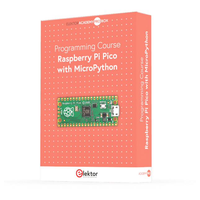
Elektor Academy Pro Raspberry Pi Pico with MicroPython (Programmierkurs)
Dieser komplette Mikrocontroller-Programmierkurs auf Basis des Raspberry Pi Pico umfasst ein Lehrbuch, ein Komponenten-Kit, praxisnahe Projekte sowie einen umfassenden Online-Kurs mit Simulationen. Er eignet sich ideal für das schrittweise Erlernen der Embedded-Programmierung mit Arduino anhand eines praktischen, hands-on Ansatzes. Eine praxisnahe Einführung in Embedded Systems mit dem Raspberry Pi Pico Dieser Kurs richtet sich an Personen ohne Vorkenntnisse im Bereich Embedded Systems, die einen strukturierten und beispielbasierten Einstieg suchen. Ein Kit bestehend aus LEDs und Widerständen, Schaltern, Sensoren und Aktoren, Displays, einem Breadboard und Kabeln sowie weiteren Komponenten ist enthalten. Diese werden im Kurs verwendet, um Beispielanwendungen zu veranschaulichen. Vorkenntnisse mit Arduino oder Embedded-Entwicklung sind nicht erforderlich. Jeder Abschnitt enthält praktische Beispiele und Mini-Projekte, die wichtige Konzepte festigen und zur weiteren Vertiefung anregen. Am Ende des Kurses werden Sie nicht nur in der Lage sein, die Beispiele nachzuvollziehen, sondern auch eigene Ideen und Anwendungen umzusetzen. Was werden Sie lernen? Programmierung von Mikrocontrollern in MicroPython mit dem Raspberry Pi Pico unter Verwendung der Thonny IDE Arbeiten mit digitalen Ein- und Ausgängen, Auslesen von Tastern und Encodern, Steuern von LEDs und Relais Auslesen analoger Eingänge, Spannungen und analoger Sensoren Erzeugung analoger Ausgangssignale und PWM Verwendung serieller Kommunikation wie UART, I²C und SPI zur Steuerung von Displays und zum Auslesen digitaler Sensoren und SD-Karten Zeitmanagement Arbeiten mit Interrupts Echtzeit-Sensordatenerfassung und Steuerung über Taster, LEDs und Displays Steuerung von Aktoren wie Relais und Servomotoren Für wen ist dieser Kurs geeignet? Studierende und Selbstlerner im Bereich Embedded Systems Makers und IoT-Enthusiasten, die ihre Hardware-Kenntnisse verbessern möchten Lehrkräfte und Trainer, die sofort einsetzbares Unterrichtsmaterial suchen Was ist im Lieferumfang enthalten? Zugang zum vollständigen Kurs auf der Elektor Academy Pro-Lernplattform Raspberry Pi Pico Mikrocontroller-Board (+ USB-Kabel) Buch: Programming Microcontrollers in MicroPython Downloadbare Projektdateien für jedes Modul Komponenten-Set: 2× LED, rot, 5 mm LED, grün, 5 mm 3× Widerstand, 470 Ω, 0,25 W LDR Potentiometer, 10 kΩ, linear Taster Drehencoder-Modul Relaismodul DHT22 Feuchtigkeits- und Temperatursensor TM1637-kompatibles 4-stelliges 7-Segment-Display MPU-6050 IMU mit Stiftleisten SSD1306-kompatibles I²C OLED-Display Micro-SD-Kartenadapter mit Stiftleiste Buzzer SG90 Mikro-Servo ILI9341-kompatibles SPI 240×320 TFT-Display 20× Jumperkabel Breadboard Alle Programmierkurse (und Unterschiede im Inhalt) Kurs Arduino Raspberry Pi Pico with Arduino C/C++ ESP32 with Arduino C/C++ Raspberry Pi Pico with MicroPython ESP32 with MicroPython Online-Kurs Access to Arduino Course Access to Pico with Arduino C/C++ Course Access to ESP32 with Arduino C/C++ Course Access to Pico with MicroPython Course Access to ESP32 with MicroPython Course Board Uno R3 Raspberry Pi Pico ESP32 Raspberry Pi Pico ESP32 Buch Programming Microcontrollers in C/C++ Using Arduino Programming Microcontrollers in C/C++ Using Arduino Programming Microcontrollers in C/C++ Using Arduino Programming Microcontrollers in MicroPython Programming Microcontrollers in MicroPython Kit 40-teiliges Komponenten-Set 40-teiliges Komponenten-Set 40-teiliges Komponenten-Set 40-teiliges Komponenten-Set 40-teiliges Komponenten-Set
€ 69,95
Mitglieder: € 62,96
-

Elektor Bundles Universal Maker Sensor Bundle
Über 180 Projekte mit Raspberry Pi, Pico W, Arduino und ESP32 Dieses Bundle enthält das Universal Maker Sensor Kit mit zahlreichen Sensoren, Aktoren, Displays und Motoren. Es eignet sich perfekt für Umweltüberwachung, Smart-Home-Projekte, Robotik und Gamecontroller. Das neue Elektor-Buch beschreibt die Entwicklung zahlreicher Projekte mit dem Kit und den beliebten Entwicklungsboards Raspberry Pi, Raspberry Pi Pico W, Arduino Uno und der ESP32-Familie. Sie können jedes dieser Entwicklungsboards für Ihre Projekte auswählen und die bereitgestellten Programme entweder unverändert verwenden oder an Ihre Anwendungen anpassen. Dieses Bundle enthält: Buch: Universal Maker Sensor Kit (Einzelpreis: 45 €) Universal Maker Sensor Kit für Raspberry Pi, Pico W, Arduino, ESP32 (Einzelpreis: 70 €) Buch: Universal Maker Sensor Kit Lernen Sie, mehr als 35 Sensoren und Aktoren mit C++, Python und MicroPython zu verwenden Dieses Buch enthält über 180 Projekte für alle vier wichtigen Entwicklungsboards (Arduino, Raspberry Pi, Pico W und ESP32). Je nach Entwicklungsboard sind Projekte in den Programmiersprachen C, Python oder MicroPython verfügbar. Die Projekttitel, Kurzbeschreibungen, Schaltpläne und vollständigen Programmlisten sind zusammen mit ihren detaillierten Beschreibungen im Buch aufgeführt. Universal Maker Sensor Kit (für Raspberry Pi, Pico W, Arduino, ESP32) Entdecken Sie grenzenlose Kreativität mit dem Universal Maker Sensor Kit, das für Raspberry Pi, Pico W, Arduino und ESP32 entwickelt wurde. Dieses vielseitige Kit ist mit gängigen Entwicklungsplattformen kompatibel, darunter Arduino Uno R4 Minima/WiFi, Uno R3, Mega 2560, Raspberry Pi 5, 4, 3B+, 3B, Zero, Pico W und ESP32. Mit über 35 Sensoren, Aktoren und Displays eignet es sich perfekt für Projekte von Umweltüberwachung und Smart-Home-Automatisierung bis hin zu Robotik und interaktivem Gaming. Schritt-für-Schritt-Tutorials in C/C++, Python und MicroPython führen Anfänger und erfahrene Maker gleichermaßen durch 169 spannende Projekte. Features Umfassende Kompatibilität: Vollständige Unterstützung für Arduino (Uno R3, Uno R4 Minima/WiFi, Mega 2560), Raspberry Pi (5, 4, 3B+, 3B, Zero, Pico W) und ESP32. Dies ermöglicht umfassende Flexibilität auf zahlreichen Entwicklungsplattformen. Enthält Anleitungen für 169 Projekte. Umfassende Komponenten: Mehr als 35 Sensoren, Aktoren und Anzeigemodule für vielfältige Projekte wie Umweltüberwachung, Smart Home-Automatisierung, Robotik und interaktive Spielesteuerungen. Ausführliche Tutorials: Klare Schritt-für-Schritt-Anleitungen für Arduino, Raspberry Pi, Pico W, ESP32 und alle enthaltenen Komponenten. Es stehen Tutorials in C/C++, Python und MicroPython zur Verfügung, die sowohl für Anfänger als auch für erfahrene Maker geeignet sind. Für alle Kenntnisstufen geeignet: Bietet strukturierte Projekte, die Benutzer nahtlos vom Anfänger zum Fortgeschrittenen in Elektronik und Programmierung führen und so Kreativität und technisches Know-how fördern. Lieferumfang des Kits Breadboard Tastenmodul Kapazitives Bodenfeuchtemodul Flammensensormodul Gas-/Rauchsensormodul (MQ2) Gyroskop & Beschleunigungssensormodul (MPU6050) Hall-Sensormodul Infrarot-Geschwindigkeitssensormodul IR-Hindernisvermeidungssensormodul Joystickmodul PCF8591 ADC/DAC-Wandlermodul Fotowiderstandsmodul PIR-Bewegungssensormodul (HC-SR501) Potentiometermodul Pulsoximeter- und Herzfrequenzsensormodul (MAX30102) Regentropfenerkennungsmodul Echtzeituhrmodul (DS1302) Drehgebermodul Temperatursensormodul (DS18B20) Temperatur- und Feuchtigkeitssensormodul (DHT11) Temperatur, Luftfeuchtigkeit und Drucksensor (BMP280) Time-of-Flight-Mikro-LIDAR-Distanzsensor (VL53L0X) Berührungssensormodul Ultraschallsensormodul (HC-SR04) Vibrationssensormodul (SW-420) Wasserstandssensormodul I²C LCD 1602 OLED-Displaymodul (SSD1306) RGB-LED-Modul Ampelmodul 5-V-Relaismodul Kreiselpumpe L9110-Motortreibermodul Passives Summermodul Servomotor (SG90) TT-Motor ESP8266 Modul JDY-31 Bluetooth-Modul Stromversorgungsmodul Dokumentation Online-Tutorial
€ 114,95€ 94,95Bestpreis
-

Elektor Academy Pro Arduino for STM32 (Programmierkurs)
Dieser komplette Programmierkurs für STM32-Mikrocontroller umfasst ein Begleitbuch, ein Komponenten-Kit, praxisorientierte Projekte sowie einen ausführlichen Online-Kurs. Er eignet sich ideal für das schrittweise Erlernen der Programmierung von Embedded Systems mit Arduino anhand eines praxisnahen Ansatzes. Praxisorientierte Einführung in Embedded Systems mit dem STM32 Dieser Kurs richtet sich an Einsteiger im Bereich Embedded Systems, die einen strukturierten und praxisnahen Einstieg suchen. Im Lieferumfang enthalten ist ein Komponenten-Kit, das unter anderem LEDs, Widerstände, Schalter, Sensoren, Aktoren, Displays, ein Breadboard sowie Verbindungskabel umfasst. Diese Komponenten kommen im Kurs zum Einsatz, um die Beispielanwendungen zu veranschaulichen. Es sind keine Vorkenntnisse in Arduino oder der Entwicklung von Embedded-Systemen erforderlich. Jeder Abschnitt enthält praktische Beispiele und Miniprojekte, die dazu dienen, die wichtigsten Konzepte zu festigen und zu weiterführenden Experimenten anzuregen. Am Ende des Kurses sind Sie in der Lage, nicht nur die Beispiele nachzuvollziehen, sondern diese auch mit eigenen Ideen und Anwendungen zu erweitern. Was werden Sie lernen? Programmierung von Mikrocontrollern in C/C++ für STM32 unter Verwendung der Arduino IDE Arbeiten mit digitalen Ein- und Ausgängen, Auslesen von Tastern und Encodern, Steuern von LEDs und Relais Auslesen analoger Eingänge, Spannungen und analoger Sensoren Erzeugung analoger Ausgangssignale und PWM Verwendung serieller Kommunikation wie UART, I²C und SPI zur Steuerung von Displays und zum Auslesen digitaler Sensoren und SD-Karten Zeitmanagement Arbeiten mit Interrupts Echtzeit-Sensordatenerfassung und Steuerung über Taster, LEDs und Displays Steuerung von Aktoren wie Relais und Servomotoren Programme mithilfe von Haltepunkten und schrittweiser Codeausführung debuggen Für wen ist dieser Kurs geeignet? Studierende und Selbstlerner im Bereich Embedded Systems Makers und IoT-Enthusiasten, die ihre Hardware-Kenntnisse verbessern möchten Lehrkräfte und Trainer, die sofort einsetzbares Unterrichtsmaterial suchen Was ist im Lieferumfang enthalten? Zugang zum vollständigen Kurs auf der Elektor Academy Pro-Lernplattform STM32 NUCLEO-F411RE Mikrocontroller-Board (+ USB-Kabel) Buch: Arduino for STM32 Downloadbare Projektdateien für jedes Modul Komponenten-Set: 2× LED, rot, 5 mm LED, grün, 5 mm 3× Widerstand, 470 Ω, 0,25 W LDR Potentiometer, 10 kΩ, linear Taster Drehencoder-Modul Relaismodul DHT22 Feuchtigkeits- und Temperatursensor TM1637-kompatibles 4-stelliges 7-Segment-Display MPU-6050 IMU mit Stiftleisten SSD1306-kompatibles I²C OLED-Display Micro-SD-Kartenadapter mit Stiftleiste Buzzer SG90 Mikro-Servo ILI9341-kompatibles SPI 240×320 TFT-Display 20× Jumperkabel Breadboard
€ 99,95€ 84,95Bestpreis


-

, von Clemens Valens Zwei neue Arduino UNO R4 Boards: Minima und Wi-Fi
Der leistungsstarke Arduino UNO R4 ist das neueste Mitglied der kultigen Arduino UNO Familie. Es gibt ihn sogar in zwei Versionen. Werfen wir einen Blick...
-

, von Jean-François Simon RC-RICK-868-EV Funkmodem (Review)
Der RC-RICK-868 ist ein Funkmodem mit UART-Schnittstelle und LoRa-Modulation, welches für eine einfache Punkt-zu-Punkt-Kommunikation entwickelt wurde.

