Suchergebnisse für "greatfet OR one"
-

Great Scott Gadgets Acrylgehäuse für HackRF One/Pro SDR
Dieses durchsichtige Acrylgehäuse ist das offizielle Gehäuse für das HackRF One/Pro Board. Es kann das schwarze Standard-Kunststoffgehäuse des HackRF One/Pro ersetzen. Montageanleitung Verwenden Sie einen Gitarrenpick oder einen Spudger, um die HackRF One/Pro Platine aus dem schwarzen Kunststoffgehäuse zu ziehen. Setzen Sie eine lange Schraube in jede Ecke der unteren Acrylplatte ein. Sichern Sie jede lange Schraube mit einem kurzen (5 mm) Abstandshalter auf der gegenüberliegenden Seite der Platte. Legen Sie die HackRF One/Pro Platine (mit der Oberseite nach oben) auf die untere Platte und führen Sie die Enden der langen Schrauben durch die Befestigungslöcher in den Ecken der Leiterplatte. Sichern Sie die Platine mit einem langen (6 mm) Abstandshalter in jeder Ecke. Legen Sie die obere Acrylplatte auf die Leiterplatte und richten Sie die Ausschnitte mit den Erweiterungsleisten der Leiterplatte aus. Sichern Sie jede Ecke mit einer kurzen Schraube. Wichtig: Bei jedem Schritt nur handfest (nicht zu fest) anziehen.
€ 19,95
Mitglieder: € 17,96
-
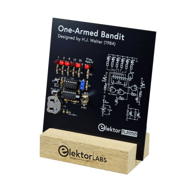
Elektor Labs Elektor Einarmiger Bandit
Ziehen Sie den Hebel nach unten, um die höchste Punktzahl zu erzielen!Dieser Elektor-Schaltungsklassiker aus dem Jahr 1984 zeigt eine spielerische Anwendung von Logik-ICs der CMOS-400x-Serie in Kombination mit LEDs, einer damals sehr beliebten Kombination. Das Projekt imitiert einen Spielautomaten mit rotierenden Ziffern.Das SpielUm das Spiel zu spielen, vereinbaren Sie zunächst die Anzahl der Runden. Spieler 1 betätigt den Schalthebel so lange wie gewünscht und lässt ihn los. Die LEDs zeigen dann die Punktzahl an, die sich aus der Summe der 50-20-10-5 aufleuchtenden Ziffern ergibt. Wenn die Play Again!-LED aufleuchtet, hat Spieler 1 eine weitere, „freie“ Runde. Wenn nicht, ist Spieler 2 am Zug. Die Spieler behalten ihre Punkte im Auge und der Spieler mit der höchsten Punktzahl gewinnt.FeaturesLEDs zeigen den Punktestand anMulti-Player und Play Again!Symbole des Elektor Heritage CircuitGetestet und geprüft von Elektor LabsEdukatives und geekiges ProjektNur Teile mit DurchgangslochLieferumfangPlatineAlle KomponentenHolzständerStücklisteWiderstände (5%, 250 mW)R1,R2,R3,R4 = 100kΩR5,R6,R7,R8,R9,R10 = 1kΩKondensatorenC1 = 4.7nF, 10%, 50V, 5mmC2 = 4.7μF, 10%, 63V, axialC3,C4 = 100nF, 10 %, 50V, Keramik X7R, 5mmHalbleiterLED1-LED6 = rot, 5mm (T1 3/4)IC1 = 74HC4024IC2 = 74HC132SonstigesS1 = Schalter, Kipphebel, 21-mm-Hebel, SPDT, tastendS2 = Schalter, taktil, 24V, 50mA, 6x6mmS3 = Schalter, Schieber, SPDTIC1,IC2 = IC-Sockel, DIP14BT1 = CR2032-Batteriehalteklammer für PlatinenmontageTischständerPCB 230098-1Nicht im Lieferumfang enthalten: BT1 = CR2032-Knopfzellenbatterie
€ 39,95€ 15,98
Bestpreis
-
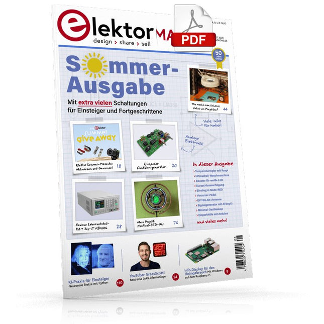
Elektor Digital Elektor 07-08/2020 (PDF)
Elektor hilft!Elektronik in herausfordernden Zeiten Info-Display für den HeimgebrauchMit Windows auf dem Raspberry Pi Einstieg in Node-REDEin visuelles blockbasiertes Open-Source-Programmierwerkzeug Elektor Sommer-Präsente Einfacher FunktionsgeneratorMit umgekehrter Signalerzeugung GreatScott! baut ein LoRa-Alarmsystem Review: Labornetzteil-Kit JOY-iT RD6006 Review: Interface-Board GreatFET One Von der Pike gelernt – XXLDiesmal: Altes aus der Elektor-Ideenkiste Des armen Mannes externe 2,4-GHz-WLAN-Antenne Einfacher Ein-Aus-Temperaturregler mit Raspberry Pi-HAT Wie macht man (schöne) Fotos von Platinen…… und elektronischen Bauteilen? Review: I²CDriver Core Review: Touchscreen Joy-View 13 LED-Booster für MikrocontrollerMit nur einem Bauteil! Experimentelle Ultraschall-Waschmaschine Review: Signalgenerator JOY-IT JDS2915Dual-Signalgenerator mit Frequenzzähler im Metallgehäuse Ampelsteuerung in PIC-Assembler Der ewige Blinker Experimenteller Hall-Sensor Kurzschlussverfolgung mit dem Milliohm- oder ESR-Meter Review: Elektor SDR-Praxis-Bundle Elektor Labs Pipeline Elektor KickstarterNun, Sie haben eine Idee um was es sich handelt Brauchen Sie wirklich dieses ganze Zeugs?Dies ist der Ort, an dem ich viele Stunden damit verbringe, an Elektronikprojekten zu arbeiten... Zutritt für Unbefugte verboten!Ein Blick ins Allerheiligste aller Elektroniker Hello, World! Wir sind Elektor, wir sind sozial! M4 + 2x A7 + GPU: Ein ungleiches DreamteamDer neue STM32MP1-SoC für gehobene Ansprüche Testing Rig für 16F18877 und ähnliche PICs Mikrocontroller-Kommunikation über SPI Sechs Oszillatoren (und der Millereffekt) Absolutes Minimal-Oszilloskop mit LED-Display Knight Rider: LED-Lauflicht mit dem ESP32 LW/MW-AM-Signalgenerator mit ATtiny13 Minimalistisches Dipmeter Preiswerter E-ScooterWas taugt ein „zugelassener“ 300-€-E-Tretroller von Lidl? Ultraschall-Rückwärtseinparkhilfe mit Arduino Uno Verzerrer-Pedal mit Operationsverstärker und Raumladungsröhren Grundlegendes für den Elektronik-Arbeitsplatz KI für Einsteiger (2)Neuronale Netze mit Linux und Python
€ 11,90
-

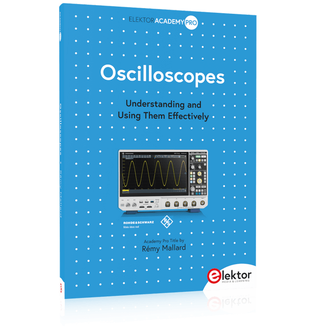
Elektor Digital Oscilloscopes (E-book)
Understanding and Using Them Effectively What happens in electronics is invisible to the naked eye. The instrument that allows to accurately visualize electrical signals, the one through which the effects of electronics become apparent to us, is the oscilloscope. Alas, when one first ventures into electronics, it is often without an oscilloscope. And one is left fumbling, both physically and mentally. Observing an electrical signal on a screen for the first time is a revelation. Nobody wishes to forgo that marvel again. There is no turning back. In electronics, if one wishes to progress with both enjoyment and understanding, an oscilloscope is essential. This marks the beginning of a period of questioning: how to choose one? And no sooner is that question answered than a whole string of others arises, which can be summed up in just one: how does one use the oscilloscope in such a way that what it displays truly reflects the reality of the signals? Rémy Mallard is a passionate communicator with a gift for making complex technical subjects understandable and engaging. In this book, he provides clear answers to essential questions about using an oscilloscope and offers a wealth of guidance to help readers explore and understand the electrical signals behind electronic systems. With his accessible style and practical insights, this book is a valuable tool for anyone eager to deepen their understanding of electronics.
€ 34,95
Mitglieder: € 27,96
-
Elektor Publishing Oscilloscopes (Book)
Understanding and Using Them Effectively What happens in electronics is invisible to the naked eye. The instrument that allows to accurately visualize electrical signals, the one through which the effects of electronics become apparent to us, is the oscilloscope. Alas, when one first ventures into electronics, it is often without an oscilloscope. And one is left fumbling, both physically and mentally. Observing an electrical signal on a screen for the first time is a revelation. Nobody wishes to forgo that marvel again. There is no turning back. In electronics, if one wishes to progress with both enjoyment and understanding, an oscilloscope is essential. This marks the beginning of a period of questioning: how to choose one? And no sooner is that question answered than a whole string of others arises, which can be summed up in just one: how does one use the oscilloscope in such a way that what it displays truly reflects the reality of the signals? Rémy Mallard is a passionate communicator with a gift for making complex technical subjects understandable and engaging. In this book, he provides clear answers to essential questions about using an oscilloscope and offers a wealth of guidance to help readers explore and understand the electrical signals behind electronic systems. With his accessible style and practical insights, this book is a valuable tool for anyone eager to deepen their understanding of electronics.
€ 44,95
Mitglieder: € 40,46
-
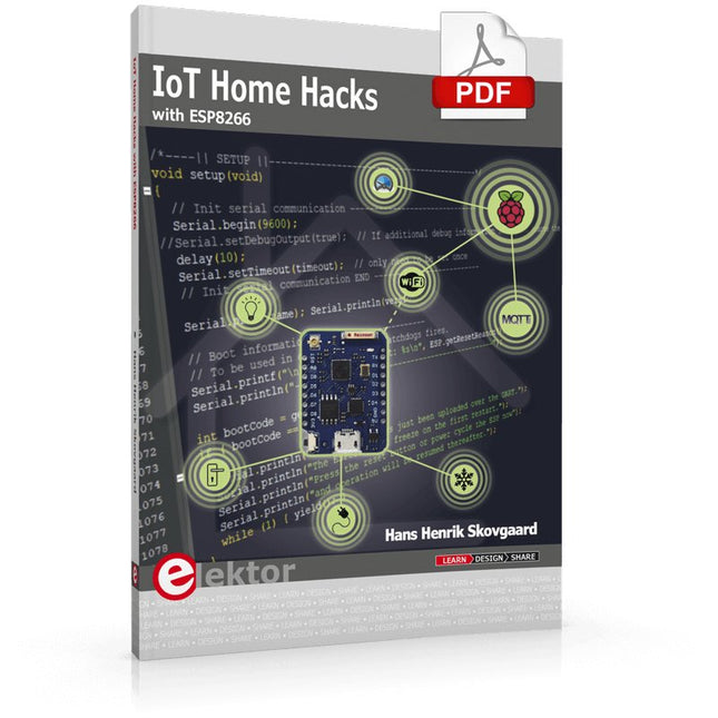
Elektor Digital IoT Home Hacks with ESP8266 (E-book)
There are many so-called 'Arduino compatible' platforms on the market. The ESP8266 – in the form of the WeMos D1 Mini Pro – is one that really stands out. This device includes WiFi Internet access and the option of a flash file system using up to 16 MB of external flash memory. Furthermore, there are ample in/output pins (though only one analogue input), PWM, I²C, and one-wire. Needless to say, you are easily able to construct many small IoT devices! This book contains the following builds: A colourful smart home accessory refrigerator controller 230 V power monitor door lock monitor and some further spin-off devices. All builds are documented together with relevant background information for further study. For your convenience, there is a small PCB for most of the designs; you can also use a perf board. You don’t need to be an expert but the minimum recommended essentials include basic experience with a PC, software, and hardware, including the ability to surf the Internet and assemble PCBs. And of course: A handle was kept on development costs. All custom software for the IoT devices and PCB layouts are available for free download from at Elektor.com.
€ 34,95
Mitglieder: € 27,96
-

Elektor Digital Vanderveen Trans Tube Amplifiers (E-book)
Menno van der Veen is well known for his research publications on tube amplifiers used in audio systems. In this book he describes one of his research projects which focuses on the question of whether full compensation for distortion in tubes and output transformers is possible. In the past, a variety of techniques have been developed. One of them has largely been forgotten: trans-conductance, which means converting current into voltage or voltage into current. Menno van der Veen has breathed new life into this technique with his research project titled “Trans”. This book discusses all aspects of this method and discusses its pitfalls. These pitfalls are addressed one by one. The end result is a set of stringent requirements for Trans amplifiers. Armed with these requirements, Menno then develops new Trans amplifiers, starting with Transie 1 and Transie 2. These DC-coupled, single-ended tube amplifiers have unusually good characteristics and are suitable for hobbyist construction. Next the Trans principle is applied to amplifiers with higher output power. A trial-and-error process ultimately leads to the Vanderveen Trans 30 amplifier, which optimizes the features of Trans. The characteristics of this amplifier are so special and unique that Menno believes he has struck gold. To ensure that variations in tube characteristics cannot interfere with optimal Trans behavior, Menno makes use of simulations and comparison with other amplifier types. This book reads like an adventure story, but it is much more – it is an account of solid research into new ways to achieve optimal audio reproduction.
€ 29,95
Mitglieder: € 23,96
-

Elektor Digital Controller Area Network Projects with ARM and Arduino (E-book)
This book details the use of the ARM Cortex-M family of processors and the Arduino Uno in practical CAN bus based projects. Inside, it gives a detailed introduction to the architecture of the Cortex-M family whilst providing examples of popular hardware and software development kits. Using these kits helps to simplify the embedded design cycle considerably and makes it easier to develop, debug, and test a CAN bus based project. The architecture of the highly popular ARM Cortex-M processor STM32F407VGT6 is described at a high level by considering its various modules. In addition, the use of the mikroC Pro for ARM and Arduino Uno CAN bus library of functions are described in detail. This book is written for students, for practising engineers, for hobbyists, and for everyone else who may need to learn more about the CAN bus and its applications. The book assumes that the reader has some knowledge of basic electronics. Knowledge of the C programming language will be useful in later chapters of the book, and familiarity with at least one microcontroller will be an advantage, especially if the reader intends to develop microcontroller based projects using CAN bus. The book should be useful source of reference to anyone interested in finding an answer to one or more of the following questions: What bus systems are available for the automotive industry? What are the principles of the CAN bus? What types of frames (or data packets) are available in a CAN bus system? How can errors be detected in a CAN bus system and how reliable is a CAN bus system? What types of CAN bus controllers are there? What are the advantages of the ARM Cortex-M microcontrollers? How can one create a CAN bus project using an ARM microcontroller? How can one create a CAN bus project using an Arduino microcontroller? How can one monitor data on the CAN bus?
€ 32,95
Mitglieder: € 26,36
-

Elektor Digital Python 3 Programming and GUIs (E-book)
This is the second edition of a book aimed at engineers, scientists, and hobbyists who want to interface PCs with hardware projects using graphical user interfaces. Desktop and web-based applications are covered. The programming language used is Python 3, which is one of the most popular languages around: speed of programming being a key feature. The book has been revised and updated with an emphasis on getting the user to produce practical designs with ease – a text editor is all that is required to produce Python programs. Hardware interfacing is achieved using an Arduino Uno as a remote slave. A full description and source code of the communication interface is given in the book. The slave provides digital and analog input and outputs. Multiple Unos can be included in one project with all control code written in Python and running on a PC One project involves a PIC microcontroller with the code provided that can be loaded into the PIC using the Uno. The web applications and server are all implemented in Python, allowing you to access your electronic hardware over the Internet. The Raspberry Pi computer can be used as your web server. An introductory chapter is provided to get you started with using Linux. The book is written for use with Debian or variations including Mint or Ubuntu. All of the programs in the book are freely available, ready to use and experiment with by way of a download from Elektor.
€ 29,95
Mitglieder: € 23,96
-

Elektor Digital Retronics (E-book)
Quite unintentionally a one-page story on an old Heathkit tube tester in the December 2004 edition of Elektor magazine spawned dozens of ‘Retronics’ tales appearing with a monthly cadence, and attracting a steady flow of reader feedback and contributions to the series. Since launching his Retronics columns, Elektor Editor Jan Buiting has never been short of copy to print, or vintage equipment to marvel at. This book is a compilation of about 80 Retronics installments published between 2004 and 2012. The stories cover vintage test equipment, prehistoric computers, long forgotten components, and Elektor blockbuster projects, all aiming to make engineers smile, sit up, object, drool, or experience a whiff of nostalgia. To reflect that our memories are constantly playing tricks on us, and honoring that “one man’s rubbish is another man’s gem”, the tales in the book purposely have no chronological order, and no bias in favor of transistor or tube, microprocessor or discrete part, audio or RF, DIY or professional, dry or narrative style. Although vastly diff erent in subject matter, all tales in the book are told with personal gusto because Retronics is about sentiment in electronics engineering, construction and repair, be it to reminisce about a 1960s Tektronix scope with a cleaning lady as a feature, or a 1928 PanSanitor box for dubious medical use. Owners of this book are advised to not exceed one Retronics tale per working day, preferably consumed in the evening hours under lamp light, in a comfortable chair, with a piece of vintage electronic equipment close and powered up.
€ 24,95
Mitglieder: € 19,96
-

Great Scott Gadgets Great Scott Gadgets ANT500 Teleskopantenne (75 MHz – 1 GHz)
ANT500 von Great Scott Gadgets ist eine Teleskopantenne für den Betrieb von 75 MHz bis 1 GHz. Ihre Gesamtlänge ist von 20 cm bis 88 cm konfigurierbar. ANT500 ist aus rostfreiem Stahl gefertigt und verfügt über einen SMA-Stecker, eine drehbare Welle und einen verstellbaren Winkel. ANT500 ist eine 50-Ohm-Antenne für allgemeine Zwecke. Sie ist die perfekt Einstiegsantenne für die Verwendung mit HackRF One/Pro.
€ 34,95
Mitglieder: € 31,46


-

, von Burkhard Kainka Erste Erfahrungen mit dem HackRF One (Review)
Als ich den HackRF One zum ersten Mal in meinen Händen hielt, wusste ich fast nichts über das Gerät, außer dass es ein SDR-Empfänger und...
