Dieses Board ermöglicht es dem Raspberry Pi Pico (angeschlossen über die Stiftleiste), zwei Motoren gleichzeitig mit voller Vorwärts-, Rückwärts- und Stoppsteuerung anzutreiben, was es ideal für Pico-gesteuerte Buggy-Projekte macht. Alternativ kann die Platine auch zum Betrieb eines Schrittmotors verwendet werden. Die Platine ist mit dem Motortreiber-IC DRV8833 ausgestattet, der über einen integrierten Kurzschluss-, Überstrom- und Wärmeschutz verfügt.
Die Platine hat 4 externe Anschlüsse für GPIO-Pins und eine 3-V- und GND-Versorgung vom Pico. Dies ermöglicht zusätzliche IO-Optionen für Ihre Buggy-Bauten, die vom Pico gelesen oder gesteuert werden können. Außerdem gibt es einen Ein/Aus-Schalter und eine Power-Status-LED, so dass Sie auf einen Blick sehen können, ob das Board eingeschaltet ist, und Ihre Batterien schonen können, wenn Ihr Projekt nicht in Gebrauch ist.
Um die Motortreiberplatine verwenden zu können, muss der Pico über eine verlötete Stiftleiste verfügen und fest in den Stecker eingesteckt werden. Die Platine erzeugt eine geregelte Stromversorgung, die in den 40-poligen Stecker eingespeist wird, um den Pico mit Strom zu versorgen, so dass dieser nicht direkt mit Strom versorgt werden muss. Die Motortreiberplatine wird entweder über Schraubklemmen oder einen Servostecker versorgt.
Kitronik hat ein Micro-Python Modul und Beispielcode entwickelt, um die Verwendung des Motor Driver Boards mit dem Pico zu unterstützen. Dieser Code ist im GitHub Repo verfügbar.
Merkmale
Ein kompaktes und dennoch funktionsreiches Board, das als Herzstück Ihrer Raspberry Pi Pico Roboter-Buggy-Projekte entwickelt wurde.
Die Platine kann 2 Motoren gleichzeitig mit voller Vorwärts-, Rückwärts- und Stoppsteuerung antreiben.
Sie enthält den Motortreiber-IC DRV8833, der über einen integrierten Kurzschluss-, Überstrom- und Überhitzungsschutz verfügt.
Darüber hinaus verfügt die Platine über einen Ein/Aus-Schalter und eine Power-Status-LED.
Die Stromversorgung der Platine erfolgt über einen Klemmenleistenanschluss.
Die 3V- und GND-Pins sind ebenfalls herausgebrochen, so dass externe Geräte mit Strom versorgt werden können.
Programmieren Sie es mit MicroPython über einen Editor wie den Thonny-Editor.
Abmessungen: 63 mm (L) x 35 mm (B) x 11,6 mm (H)
Download
Datenblatt
Dieses Kit enthält das größte Sortiment an Bits von iFixit, komplett mit allen Schraubendreherköpfen, die Sie für jedes Reparatur- oder Heimwerkerprojekt benötigen. Es umfasst Standard-Bits wie Kreuzschlitz- und Flachkopf-Bits in einer breiten Palette von Größen, um alles von der Präzisionsreparatur von Elektronikgeräten bis hin zu Heimwerkerprojekten zu bewältigen. Und es wäre kein iFixit-Bit-Set, wenn es nicht alle exotischen Bits von Pentalobes für die Reparatur von Apple iPhone und MacBook bis hin zu Gamebits für Ihre Vintage-Nintendo-Konsolen enthalten würde.
Alle Bitsätze der nächsten Generation wurden neu gestaltet, um den Komfort und die Benutzerfreundlichkeit zu maximieren. Der Bit-Set-Deckel wird mit Magneten an Ort und Stelle gehalten, um die Lebensdauer des Produkts zu verlängern (keine kaputten Scharniere oder Verschlüsse mehr) und wird auch an der Rückseite des Bit-Set-Koffers befestigt, damit er Ihnen bei der Arbeit nicht im Weg ist. Wenn Sie Hilfe bei der Organisation Ihrer Schrauben und Teile benötigen, können Sie die integrierte Sortierschale im Deckel verwenden. Die 4-mm-Bits wurden angepasst und verfügen nun über einen längeren Hals für eine tiefere und präzisere Reichweite.
Toolkit enthält
Leicht zu öffnendes magnetisiertes Gehäuse
Mitglied mit integriertem Sortierfach
4-mm-Aluminium-Bit-Treiber
1/4' Aluminium-Bit-Treiber
4-mm-Schraubendreherbits
Phillips - 000, 00, 0
Flachkopf – 1, 1,5, 2, 2,5, 3, 3,5 mm
Torx – T2, T3, T4, T5
Torx-Sicherheit – TR6, TR7, TR8
Pentalobe - P2, P5, P6
JIS - 000, 00, 0, 1
Sechskant – 0,7, 0,9, 1,3, 1,5 mm
Sechskantsicherheit – 2, 2,5, 3, 3,5 mm
Dreipunkt – Y000, Y00, Y0, Y1
Steckschlüssel – 2,5, 3, 3,5, 4, 4,5, 5, 5,5 mm
Spielbit - 3,8, 4,5 mm
Spanner - 4, 6
Dreieck - 2, 2,2, 2,6, 3 mm
Ovales Gebiss
iPhone-Abstandsbit
Sim-Auswurfbit
Magnetischer Pickup-Bit
1/4'-Schraubendreher-Bits
Phillips – 1, 2, 3
Flachkopf – 4, 5, 6, 7, 8 mm
Sechskantsicherheit – 4, 5, 6, 7, 8 mm
Sechskantsicherheit SAE – 1/8, 9/64, 5/32, 3/16, 7/32, 1/4
Pozidriv - PZ0, PZ1, PZ2, PZ3
Drehmomentsatz - 6, 8, 10
Spanner - 8, 10, 12
Quadrat - 0, 1, 2, 3
Spline – M5, M6, M8
Torx-Sicherheit – TR9, TR10, TR15, TR20, TR25, TR27, TR30, TR35, TR40
Tri Wing 1, 2, 3, 4
Kupplung 1, 2, 3
Schrader-Ventil
Hakenantrieb
1/4' auf 4 mm Adapter
1/4'-Treiber auf 1/4'-Buchse
1/4'-Schraubendreher auf 3/8'-Stecknuss
1/4'-Buchse auf 1/4'-Schraubendreher
Technische Daten
Bit-Metall: 6150 Stahl
Treibermaterial: Eloxiertes Aluminium
Gehäusematerial: ABS
Schaum: EVA
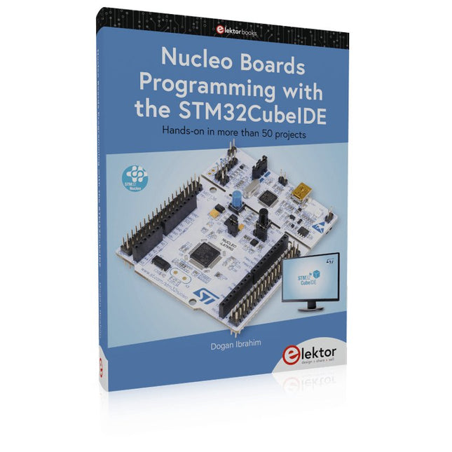
Hands-on in more than 50 projects
STM32 Nucleo family of processors are manufactured by STMicroelectronics. These are low-cost ARM microcontroller development boards. This book is about developing projects using the popular STM32CubeIDE software with the Nucleo-L476RG development board. In the early Chapters of the book the architecture of the Nucleo family is briefly described.
The book covers many projects using most features of the Nucleo-L476RG development board where the full software listings for the STM32CubeIDE are given for each project together with extensive descriptions. The projects range from simple flashing LEDs to more complex projects using modules, devices, and libraries such as GPIO, ADC, DAC, I²C, SPI, LCD, DMA, analogue inputs, power management, X-CUBE-MEMS1 library, DEBUGGING, and others. In addition, several projects are given using the popular Nucleo Expansion Boards. These Expansion Boards plug on top of the Nucleo development boards and provide sensors, relays, accelerometers, gyroscopes, Wi-Fi, and many others. Using an expansion board together with the X-CUBE-MEMS1 library simplifies the task of project development considerably.
All the projects in the book have been tested and are working. The following sub-headings are given for each project: Project Title, Description, Aim, Block Diagram, Circuit Diagram, and Program Listing for the STM32CubeIDE.
In this book you will learn about
STM32 microcontroller architecture;
the Nucleo-L476RG development board in projects using the STM32CubeIDE integrated software development tool;
external and internal interrupts and DMA;
DEBUG, a program developed using the STM32CubeIDE;
the MCU in Sleep, Stop, and in Standby modes;
Nucleo Expansion Boards with the Nucleo development boards.
What you need
a PC with Internet connection and a USB port;
STM32CubeIDE software (available at STMicroelectronics website free of charge)
the project source files, available from the book’s webpage hosted by Elektor;
Nucleo-L476RG development board;
simple electronic devices such as LEDs, temperature sensor, I²C and SPI chips, and a few more;
Nucleo Expansion Boards (optional).
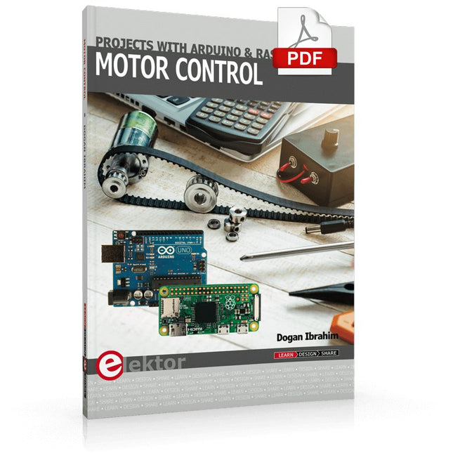
This book is about DC electric motors and their use in Arduino and Raspberry Pi Zero W based projects. The book includes many tested and working projects where each project has the following sub-headings:
Title of the project
Description of the project
Block diagram
Circuit diagram
Project assembly
Complete program listing of the project
Full description of the program
The projects in the book cover the standard DC motors, stepper motors, servo motors, and mobile robots. The book is aimed at students, hobbyists, and anyone else interested in developing microcontroller based projects using the Arduino Uno or the Raspberry Pi Zero W.
One of the nice features of this book is that it gives complete projects for remote control of a mobile robot from a mobile phone, using the Arduino Uno as well as the Raspberry Pi Zero W development boards. These projects are developed using Wi-Fi as well as the Bluetooth connectivity with the mobile phone. Readers should be able to move a robot forward, reverse, turn left, or turn right by sending simple commands from a mobile phone. Full program listings of all the projects as well as the detailed program descriptions are given in the book. Users should be able to use the projects as they are presented, or modify them to suit to their own needs.
STM32 Nucleo family of processors are manufactured by STMicroelectronics. These are low-cost ARM microcontroller development boards. This book is about developing projects using the popular Nucleo development board. In the early chapters of the book, the architecture of the Nucleo family is briefly described.
Software development tools that can be used with the Nucleo boards such as the Mbed, Keil MDK, TrueSTUDIO, and the System Workbench are described briefly in later Chapters.
The book covers many projects using most features of the STM32 Nucleo development boards where the full software listings for Mbed and System Workbench are given for every project. The projects range from simple flashing LEDs to more complex projects using modules and devices such as GPIO, ADC, DAC, I²C, LCD, analog inputs and others.
In addition, several projects are given using the Nucleo Expansion Boards, including popular expansion boards such as solid-state relay, MEMS and environmental sensors, DC motor driver, Wi-Fi, and stepper motor driver.
These Expansion Boards plug on top of the Nucleo development boards and simplify the task of project development considerably.
Features of this book
Learn the architecture of the STM32 microcontrollers
Learn how to use the Nucleo development board in projects using Mbed and System Workbench Toolchains
Learn how to use the Nucleo Expansion Boards with the Nucleo development boards
Update
The Mbed compiler has been replaced with two software packages: The Mbed Studio and Keil Studio Cloud. Both of these software packages are free of charge and are available on the Internet. If you need assistance using the Keil Studio Cloud, please download the Guide below.
The FRDM-MCXN947 is a compact and versatile development board designed for rapid prototyping with MCX N94 and N54 microcontrollers. It features industry-standard headers for easy access to the MCU's I/Os, integrated open-standard serial interfaces, external flash memory, and an onboard MCU-Link debugger.
Technische Daten
Microcontroller
MCX-N947 Dual Arm Cortex-M33 cores @ 150 MHz each with optimized performance efficiency, up to 2 MB dual-bank flash with optional full ECC RAM, External flash
Accelerators: Neural Processing Unit, PowerQuad, Smart DMA, etc.
Memory Expansion
*DNP Micro SD card socket
Connectivity
Ethernet Phy and connector
HS USB-C connectors
SPI/I²C/UART connector (PMOD/mikroBUS, DNP)
WiFi connector (PMOD/mikroBUS, DNP)
CAN-FD transceiver
Debug
On-board MCU-Link debugger with CMSIS-DAP
JTAG/SWD connector
Sensor
P3T1755 I³C/I²C Temp Sensor, Touch Pad
Expansion Options
Arduino Header (with FRDM expansion rows)
FRDM Header
FlexIO/LCD Header
SmartDMA/Camera Header
Pmod *DNP
mikroBUS
User Interface
RGB user LED, plus Reset, ISP, Wakeup buttons
Lieferumfang
1x FRDM-MCXN947 Development Board
1x USB-C Cable
1x Quick Start Guide
Downloads
Datasheet
Block diagram
This book is for people who want to understand how AC drives (also known as inverter drives) work and how they are used in industry by showing mainly the practical design and application of drives.
The key principles of power electronics are described and presented in a simple way, as are the basics of both DC and AC motors. The different parts of an AC drive are explained, together with the theoretical background and the practical design issues such as cooling and protection.
An important part of the book gives details of the features and functions often found in AC drives and gives practical advice on how and where to use these. Also described is future drive technology, including a matrix inverter.
The mathematics is kept to an essential minimum. Some basic understanding of mechanical and electrical theory is presumed, and a basic knowledge of single andthree phase AC systems would be useful.
Anyone who uses or installs drives, or is just interested in how these powerful electronic products operate and control modern industry, will find this book fascinating and informative.
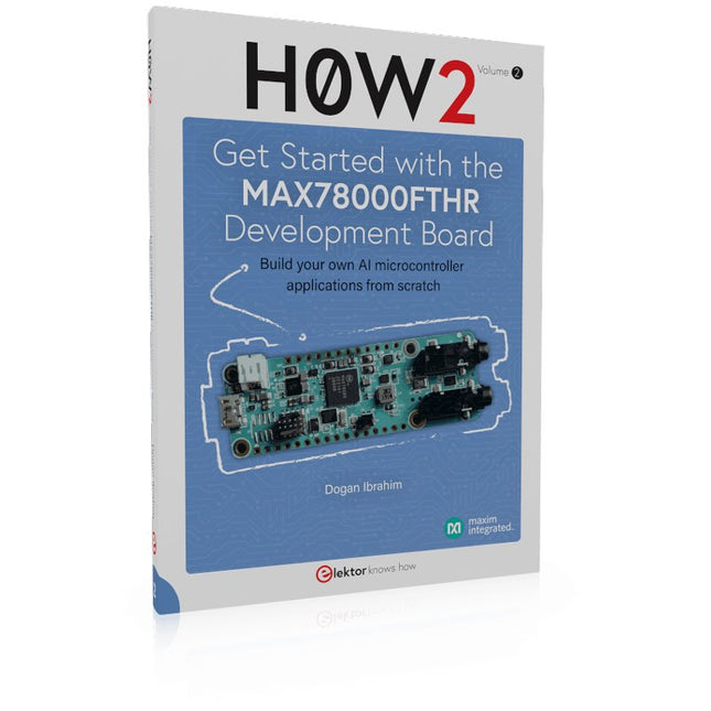
Build your own AI microcontroller applications from scratch
The MAX78000FTHR from Maxim Integrated is a small development board based on the MAX78000 MCU. The main usage of this board is in artificial intelligence applications (AI) which generally require large amounts of processing power and memory. It marries an Arm Cortex-M4 processor with a floating-point unit (FPU), convolutional neural network (CNN) accelerator, and RISC-V core into a single device. It is designed for ultra-low power consumption, making it ideal for many portable AI-based applications.
This book is project-based and aims to teach the basic features of the MAX78000FTHR. It demonstrates how it can be used in various classical and AI-based projects. Each project is described in detail and complete program listings are provided. Readers should be able to use the projects as they are, or modify them to suit their applications. This book covers the following features of the MAX78000FTHR microcontroller development board:
Onboard LEDs and buttons
External LEDs and buttons
Using analog-to-digital converters
I²C projects
SPI projects
UART projects
External interrupts and timer interrupts
Using the onboard microphone
Using the onboard camera
Convolutional Neural Network
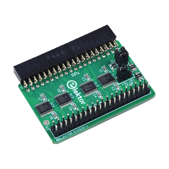
Wenn Sie regelmäßig mit dem Raspberry Pi experimentieren und eine Vielzahl von externer Hardware über die Stiftleiste an den GPIO-Port anschließen, haben Sie in der Vergangenheit vielleicht schon einige Schäden verursacht. Das Elektor Raspberry Pi Buffer Board ist dazu da, dies zu verhindern! Das Board ist kompatibel mit Raspberry Pi Zero, Zero 2 (W), 3, 4, 5, 400 und 500.
Alle 26 GPIOs sind mit bidirektionalen Spannungswandlern gepuffert, um den Raspberry Pi beim Experimentieren mit neuen Schaltungen zu schützen. Die Platine ist dafür vorgesehen, auf der Rückseite des Raspberry Pi 400/500 eingesetzt zu werden. Der Stecker zum Anschluss an den Raspberry Pi ist eine rechtwinklige 40-polige Buchse (2x20). Die Platine ist nur ein wenig breiter. An die Pufferausgangsbuchse kann ein 40-poliges Flachbandkabel mit entsprechenden 2x20-Steckern angeschlossen werden, um z. B. mit einer Schaltung auf einem Breadboard oder einer Platine zu experimentieren.
Die Schaltung verwendet 4x TXS0108E ICs von Texas Instruments. Die Platine lässt sich auch auf einem Raspberry Pi aufstellen.
Downloads
Schematics
Layout
Merkmale
Eingebaute USB-zu-Seriell-Schnittstelle
Eingebaute PCB-Antenne
Angetrieben durch Pineseed BL602 SoC mit Pinenut-Modell: 12S-Stempel
2 MB Flash
USB-C-Anschluss
Geeignet für Steckbrett-BIY-Projekte
An Bord befinden sich drei Farb-LEDs
Abmessungen: 25,4 x 44,0 mm
Hinweis: USB-Kabel ist nicht im Lieferumfang enthalten.
Die MotoPi-Platine ist eine Erweiterungsplatine zur Ansteuerung und Verwendung von bis zu 16 PWM-gesteuerten 5-V-Servomotoren.
Der eigene Taktgeber auf dem MotoPi sorgt für ein sehr genaues PWM-Signal und somit auch für eine genaue Positionierung.
Die Platine verfügt über 2 Eingänge für eine Spannung von 4,8-6 V, über die zusammen bis zu 11 A eingespeist werden können, so dass eine optimale Versorgung der Motoren stets gewährleistet ist und somit auch größere Projekte mit ausreichend Strom beliefert werden können.
Die Versorgung läuft zentral über den MotoPi, der für jeden Motor separat einen Anschluss für Spannung, Masse und die Steuerleitung zur Verfügung stellt.
Durch den eingebauten Kondensator wird der Strom zusätzlich gepuffert. Hierdurch wird das Einbrechen der Spannung bei kurzzeitiger Mehrbelastung abgemildert, die sonst zum Ruckeln führen könnte. Zusätzlich hat man noch die Möglichkeit, einen weiteren Kondensator anzuschließen.
Der integrierte Analog-Digital-Wandler bietet neue Möglichkeiten wie z. B. die Steuerung über einen Joystick.
Die Ansteuerung und Programmierung der Motoren kann (wie gewohnt) weiterhin bequem über den Raspberry Pi bedient werden. Anleitung und Codebeispiele erlauben auch Einsteigern, schnell Ergebnisse zu erzielen.
Besonderheiten
16 Kanäle, eigener Taktgeber für Servomotoren (PWM), inkl. Analog-Digital-Wandler
Eingang 1
Hohlstecker 5,5 / 2,1 mm, 4,8-6 V, 5 A max.
Eingang 2
Schraubklemme, 4,8-6 V, 6 A max.
Kompatibel mit
Raspberry Pi A+, B+, 2B, 3B
Maße (BxHxT)
65 x 24 x 56 mm
Lieferumfang
Platine, Bedienungsanleitung, Befestigungsmaterial, Retail-Verpackung
Hands-on in more than 50 projects
STM32 Nucleo family of processors are manufactured by STMicroelectronics. These are low-cost ARM microcontroller development boards. This book is about developing projects using the popular STM32CubeIDE software with the Nucleo-L476RG development board. In the early Chapters of the book the architecture of the Nucleo family is briefly described.
The book covers many projects using most features of the Nucleo-L476RG development board where the full software listings for the STM32CubeIDE are given for each project together with extensive descriptions. The projects range from simple flashing LEDs to more complex projects using modules, devices, and libraries such as GPIO, ADC, DAC, I²C, SPI, LCD, DMA, analogue inputs, power management, X-CUBE-MEMS1 library, DEBUGGING, and others. In addition, several projects are given using the popular Nucleo Expansion Boards. These Expansion Boards plug on top of the Nucleo development boards and provide sensors, relays, accelerometers, gyroscopes, Wi-Fi, and many others. Using an expansion board together with the X-CUBE-MEMS1 library simplifies the task of project development considerably.
All the projects in the book have been tested and are working. The following sub-headings are given for each project: Project Title, Description, Aim, Block Diagram, Circuit Diagram, and Program Listing for the STM32CubeIDE.
In this book you will learn about
STM32 microcontroller architecture;
the Nucleo-L476RG development board in projects using the STM32CubeIDE integrated software development tool;
external and internal interrupts and DMA;
DEBUG, a program developed using the STM32CubeIDE;
the MCU in Sleep, Stop, and in Standby modes;
Nucleo Expansion Boards with the Nucleo development boards.
What you need
a PC with Internet connection and a USB port;
STM32CubeIDE software (available at STMicroelectronics website free of charge)
the project source files, available from the book’s webpage hosted by Elektor;
Nucleo-L476RG development board;
simple electronic devices such as LEDs, temperature sensor, I²C and SPI chips, and a few more;
Nucleo Expansion Boards (optional).