Aus dem Inhalt
Neues von den Röhrenherstellern
Übertragereigenschaften
Röhrenverstärker im Kopfhörerbetrieb
Line-Vorverstärker mit Trioden
Eintakt-A-Endstufe mit KT 120
Leistungsstarke Gegentakt-AB-Endstufe mit KT 120
Elektronischer Laustärkesteller
Aktivantenne mit der Röhre EF 183
Wobbelgenerator zum Abgleich von Rundfunkempfängern
Die Sorgen mit dem bleifreien Lötzinn
Röhrengrenzdaten
Die 300B – ein Vergleich
Technik zum Anfassen
Röhrendaten mit Sockelschaltungen
Hinweis
Einige Platinenlayouts sind im Heft unscharf abgebildet worden. Die entsprechenden Zeichnungen stehen als PDF zum Download.
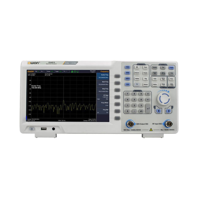
Der OWON XSA815-TG 9 kHz-1,5 GHz ist ein kostengünstiger Spektrumanalysator mit Tracking-Generator und einer Frequenzauflösung von 1 Hz.FeaturesFrequenzbereich von 9 kHz bis 1,500009 GHz9-Zoll-Display9 kHz bis 1 MHz -95 dBm Angezeigter durchschnittlicher Geräuschpegel, 1 MHz bis 500 MHz 140 dBm (typisch), Phasenrauschen-10 kHz 100 kHz 1 MHz Auflösungsbandbreite (-3 dB): 1 Hz bis 1 MHz, in der Reihenfolge 1-3-5-10Tracking-Generator-Kit: 100 kHz bis 1,500009 GHzTechnische DatenFrequenzbereich9 kHz bis 500.009 MHzFrequenzauslösung1 HzFrequenzspanne9 kHz bis 1.500009 GHzSpan Range0 Hz, 100 Hz to max frequency of instrumentSpan Uncertainty± span / (sweep points-1)SSB Phase Noise (20°C to 30°C, fc=1 GHz) Carrier Offset10 kHz Resolution Bandwidth (-3 dB)1 Hz to 1 MHz, in 1-3-5-10 sequenceRBW AccuracyResolution Filter Shape Factor (60 dB: 3 dB)Video Bandwidth (-3 dB)10 Hz to 1 MHz, in 1-3-5-10 sequenceAmplitude measurement rangeDANL to +10 dBm, 100 kHz to 10 MHz, Preamp Off DANL to +20 dBm, 10 MHz to 1.5 GHz, Preamp OffReference Level-80 dBm to +30 dBm, 0.01dB by stepPreamp20 dB, nominal, 100 kHz to 1.5 GHzInput Attenuator0 to 40 dB, 1 dB by step Display Average Noise Level Input attenuation = 0 dB, RBW = VBW = 100 Hz, sample detector, trace average ≥ 50, 20°C to 30°C, input impedance = 50 Ω)Preamp Off 9 kHz to 1 MHz-95 dBm (Typical), Preamp Off 1 MHz to 500 MHz-140 dBm (Typical), Preamp On 100 kHz to 1 MHz-135 dBm (Typical), Preamp On 1 MHz to 500 MHz-160 dBm (Typical),Tracking Generator (optional) Frequency Range100 kHz to 1.500009 GHzOutput power level range-40 dBm to 0 dBmOutput level resolution 1 dB Output flatnessRelative to 50 MHz | ±3 dBTracking generator spuriousHarmonic spurious -30 dBc (Tracking generator output power -10 dBm) Non-harmonic spurious -40 dBc (Tracking generator output power -10 dBm)Tracking generator to input terminal isolation-60 dB (Tracking generator output power 0 dBm)Tracking generator to input terminal isolation-60 dB (Tracking generator output power 0 dBm)Tracking generator to input terminal isolation-60 dB (Tracking generator output power 0 dBm)Abmessungen375 x 185 x 120 mmGewicht3,7 kgLieferumfang1x XSA815-TG1x 220 V AC-Netzkabel1x USB-Kabel1x SchnellstartanleitungDownloadsQuick GuideSpecifications
Die Punk Console Schaltung ist ein fortgeschrittener Tutorial, um Sie mit dem V-One Bohrer vertraut zu machen. Lernen Sie, wie man eine doppelseitige Platine erstellt und durch das Drehen der Knöpfe Musik erzeugt!
Das Kit enthält:
2x grüne LEDs
8x 1k Widerstände
3x 0.01uF Kondensatoren
2x 500K Trimpots
1x 556 Timer
1x Piezo-Summer
1x 9V Batterie
1x 9V Batterieanschluss
Nieten und ein V-One Bohrer werden benötigt.
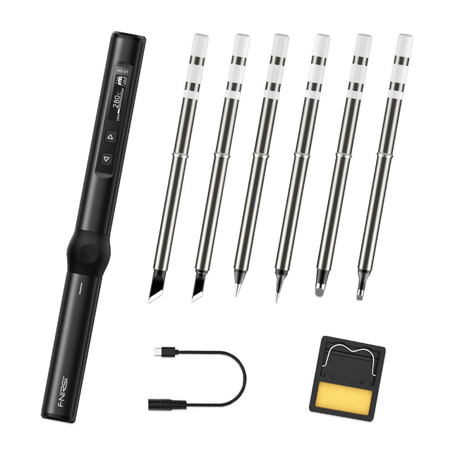
Das perfekte Werkzeug für schnelle Reparaturen
Der HS-01 ist ein leistungsstarker, regulierbarer Smart-Lötkolben mit einem eingebauten 0,87"-OLED-Display, der schnell Temperaturen zwischen 80-420°C erreicht. Das Display zeigt alle wichtigen Informationen an, darunter den Status der Temperaturstufe, die eingestellte Temperatur, die Versorgungsspannung und den Leistungsanteil. Sie können die Eingangsspannung von 9-20 V direkt im Menü nach Ihren Bedürfnissen einstellen. Der integrierte Schlafmodus schaltet den Lötkolben nach 30 Minuten automatisch ab.
Features
96 W Eingang (DC)
65 W PD-Leistung
OLED-Display
Konstante Temperatur & schnelles Aufheizen
CNC-Metallintegralguss
Intelligenter Sicherheits-Verbrühungsschutz
Mini-Taschenformat
Ergonomisches Design
Aluminiummaterial
Links-/Rechtsschalter
Effiziente Wärmestrahlung
Induktiver Schlaf
Farbe: Schwarz
Technische Daten
Leistung
65 W
Display
0,87" OLED
Betriebsspannung
9-20 VDC
Stromversorgung
USB-C
Temperaturbereich
80-420°C
Schnellladeprotokoll
PD-Trigger
Abmessungen
184 x 20 x 20 mm
Gewicht
56 g
Spannungswahl
Betriebsspannung
20 V
15 V
12 V
9 V
Betriebsstrom
≥3,25 A
≥2,5 A
≥2 A
≥1,5 A
Leistung
65 W
37,5 W
24 W
13,5 W
Zinnschmelzzeit
8s
12s
17s
30s
Lieferumfang
1x Smart Lötkolben FNRISI HS-01
6x Lötkolbenspitzen (HS01-BC2, HS01-KR, HS01-K65, HS01-B2, HS01-ILS, HS01-BC3)
1x DC-zu-USB-C-Kabel
1x Mini-Lötkolbenständer
1x Handbuch
Erforderlich
Netzteil
USB-C Kabel
Downloads
Manual
Firmware V0.3.s19
Das Whadda 3D-Weihnachtsbaum-Kit richtet sich an Bastler und Anfänger, die sich für Löten und Elektronik interessieren. Mit diesem DIY-Kit können Sie einen festlichen LED-Weihnachtsbaum bauen.
Features
16 blinkende rote LEDs
Zusätzliche grüne und gelbe LEDs zur individuellen Gestaltung Ihres Baumes
Kann an Drähten aufgehängt und durch diese geführt werden
Wird mit 12 V Gleichstrom betrieben (z. B. in Autos)
Technische Daten
Geringer Stromverbrauch
8 mA
Stromversorgung
9 V Batterie (nicht im Lieferumfang enthalten)
Abmessungen
102 x 88 x 80 mm
Gewicht
65 g
Downloads
Manual
Third, extended and revised edition with AVR Playground and Elektor Uno R4
Arduino boards have become hugely successful. They are simple to use and inexpensive. This book will not only familiarize you with the world of Arduino but it will also teach you how to program microcontrollers in general. In this book theory is put into practice on an Arduino board using the Arduino programming environment.
Some hardware is developed too: a multi-purpose shield to build some of the experiments from the first 10 chapters on; the AVR Playground, a real Arduino-based microcontroller development board for comfortable application development, and the Elektor Uno R4, an Arduino Uno R3 on steroids.
The author, an Elektor Expert, provides the reader with the basic theoretical knowledge necessary to program any microcontroller: inputs and outputs (analog and digital), interrupts, communication busses (RS-232, SPI, I²C, 1-wire, SMBus, etc.), timers, and much more. The programs and sketches presented in the book show how to use various common electronic components: matrix keyboards, displays (LED, alphanumeric and graphic color LCD), motors, sensors (temperature, pressure, humidity, sound, light, and infrared), rotary encoders, piezo buzzers, pushbuttons, relays, etc. This book will be your first book about microcontrollers with a happy ending!
This book is for you if you are a beginner in microcontrollers, an Arduino user (hobbyist, tinkerer, artist, etc.) wishing to deepen your knowledge,an Electronics Graduate under Undergraduate student or a teacher looking for ideas.
Thanks to Arduino the implementation of the presented concepts is simple and fun. Some of the proposed projects are very original:
Money Game
Misophone (a musical fork)
Car GPS Scrambler
Weather Station
DCF77 Decoder
Illegal Time Transmitter
Infrared Remote Manipulator
Annoying Sound Generator
Italian Horn Alarm
Overheating Detector
PID Controller
Data Logger
SVG File Oscilloscope
6-Channel Voltmeter
All projects and code examples in this book have been tried and tested on an Arduino Uno board. They should also work with the Arduino Mega and every other compatible board that exposes the Arduino shield extension connectors.
Please note
For this book, the author has designed a versatile printed circuit board that can be stacked on an Arduino board. The assembly can be used not only to try out many of the projects presented in this book but also allows for new exercises that in turn provide the opportunity to discover new techniques. Also available is a kit of parts including the PCB and all components. With this kit you can build most of the circuits described in the book and more.
Datasheets Active Components Used (.PDF file):
ATmega328 (Arduino Uno)
ATmega2560 (Arduino Mega 2560)
BC547 (bipolar transistor, chapters 7, 8, 9)
BD139 (bipolar power transistor, chapter 10)
BS170 (N-MOS transistor, chapter 8)
DCF77 (receiver module, chapter 9)
DS18B20 (temperature sensor, chapter 10)
DS18S20 (temperature sensor, chapter 10)
HP03S (pressure sensor, chapter 8)
IRF630 (N-MOS power transistor, chapter 7)
IRF9630 (P-MOS power transistor, chapter 7)
LMC6464 (quad op-amp, chapter 7)
MLX90614 (infrared sensor, chapter 10)
SHT11 (humidity sensor, chapter 8)
TS922 (dual op-amp, chapter 9)
TSOP34836 (infrared receiver, chapter 9)
TSOP1736 (infrared receiver, chapter 9)
MPX4115 (analogue pressure sensor, chapter 11)
MCCOG21605B6W-SPTLYI (I²C LCD, chapter 12)
SST25VF016B (SPI EEPROM, chapter 13)
About the author
Clemens Valens, born in the Netherlands, lives in France since 1997. Manager at Elektor Labs and Webmaster of ElektorLabs, in love with electronics, he develops microcontroller systems for fun, and sometimes for his employer too. Polyglot—he is fluent in C, C++, PASCAL, BASIC and several assembler dialects—Clemens spends most of his time on his computer while his wife, their two children and two cats try to attract his attention (only the cats succeed). Visit the author’s website: www.polyvalens.com.Authentic testimony of Hervé M., one of the first readers of the book:'I almost cried with joy when this book made me understand things in only three sentences that seemed previously completely impenetrable.'
Das DE-5000 ist ein intelligentes, hochpräzises, flexibles und einfach zu bedienendes tragbares LCR-Messgerät. Es verfügt über automatische LCR-Prüfung, 4-Draht-Kelvin-Messung, hintergrundbeleuchtetes Display mit 19999/1999-Counts, mehrere Messmodi und wählbare Testfrequenzen (100 Hz, 120 Hz, 1 kHz, 10 kHz oder 100 kHz). Das LCR-Messgerät DE-5000 ist ein praktischer Helfer für Ingenieure oder Techniker.FeaturesAuto L.C.R. CheckLs/Lp/Cs/Cp/Rs/Rp/DCR mit D/Q/θ/ESR-Messung4-Leiter-Kelvin-MessungAnzeige von 20.000 / 2.000 CountsHintergrundbeleuchtungRelativer ModusSerieller/ParallelmodusKomponentensortierfunktionAnzeige für niedrigen BatteriestandAutomatische AbschaltungTechnische DatenTestfrequenz100 Hz/120 Hz/1 kHz/10 kHz/100 kHzWiderstandsbereich20.000 Ω – 200,0 MΩDCR-Bereich200,00 Ω – 200,0 MΩKapazitätsbereich200,00 pF – 20,00 mFInduktivitätsbereich20.000 µH – 2.000 KHDisplay (Backlight-LCD)19999 / 1999 zähltWählbare Toleranz±0,25%, ±0,5%, ±1%, ±2%, ±5%, ±10%, ±20%Stromversorgung9 V BatterieAbmessungen188 x 95 x 52 mmGewicht350 g (ohne Batterie)LieferumfangDE-5000 LCR-MessgerätAlligator-Messleitungskoffer (TL-21)AC/DC-AdapterWachlinie (TL-23)TL-22 SMD-Pinzette9 V BatterieTragetascheManualDownloadsDatasheet
Das Weller WT 1013 Lötstationsset beinhaltet die Versorgungseinheit WT 1, den Lötkolben WP 80 und die Sicherheitsablage WSR 201. Es ist stapelbar und schafft so mehr Platz am Arbeitsplatz. Durch einen integrierten Nutzungssensor schaltet sich das Lötgerät automatisch ab.
Technische Daten
Kanäle
1
Stromspannung
230 V
Leistung
95 W
Anzeige
Hintergrundbeleuchtetes LCD
Temperaturbereich
50°C - 450°C
Temperaturstabilität
±2 °C
Temperaturgenauigkeit
±9 °C
Sicherung
0,5 A
Potenzialausgleich
An
WT-kompatibel
An
ESD-sicher
An
Stromkabel
EMEA
Maße
149 x 138 x 101 mm
Gewicht ca.)
1,9 kg
Inhalt:
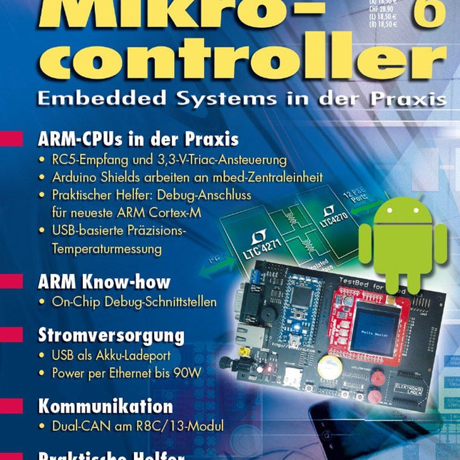
Praxis
Geisterhände – RC5-Empfang und 3,3-V-Triac-Ansteuerung mit ARM Cortex-M3
Als Vermählte grüßen … – Trägerboard für mbed-ARM-Zentraleinheit und Arduino Shields
Cortex-M: Spionage-Port sucht Anschluss – Neuer Debug-Anschluss bei aktuellen ARM Cortex-M Mikrocontrollern
Yes we CAN CAN – Dual-CAN-Port für das R8C/13-Board
ARM-Thermometer – USB-basierte Temperaturüberwachung mit Kaltstellen-Kompensation
Know-how
Nie mehr Ladehemmung – USB als Akku-Ladeport
Power up – Stromversorgung per Ethernet bis 90 W
Reise ins Innere der ARM-MCU – ARM On-Chip Debug-Schnittstellen: Möglichkeiten und Grenzen
Info
Marktübersicht – Android-Applikationen für Elektroniker
Aktuell – Companion-Chips, Eva-Kits, MCUs und Software
Noch einfacher – RS-232-DB-9 wird USB-DB-9
Wenn nichts mehr geht – Hot-Swap-I²C-Bus-Puffer mit großer Low-Pegel-Toleranz
Treibende Kraft – Energieeffiziente Motorsteuerungen skalierbar entwickeln
Weitere Hefte aus dieser Reihe:
Mikrocontroller 7 (PDF)
Mikrocontroller 5 (PDF)
Mikrocontroller 4 (PDF)
Mikrocontroller 3 (PDF)
Mikrocontroller 2 (PDF)
Mikrocontroller 1 (PDF)
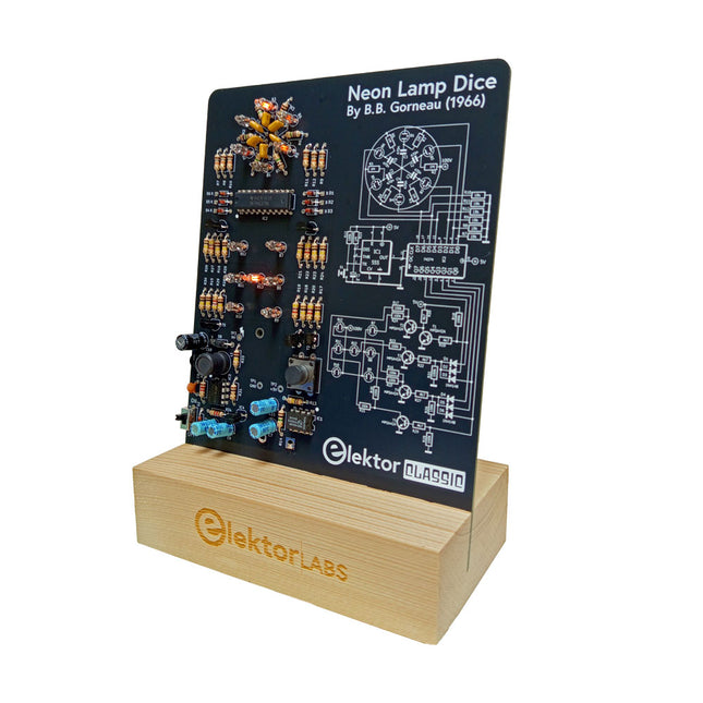
Ein Retro-Würfel mit Neon-Charakter
LED-basierte Würfel sind weit verbreitet, doch ihr Licht ist kalt. Nicht so dieser elektronische Neonwürfel, der seinen Wert mit dem warmen Schein von Neonröhren anzeigt. Er eignet sich perfekt für Spiele an kalten, dunklen Winterabenden. Die Würfelpunkte sind Neonlampen, und der Zufallszahlengenerator verfügt über sechs Neonröhren, die seine Funktion anzeigen.
Obwohl der Würfel über eine integrierte 100-V-Stromversorgung verfügt, ist er absolut sicher. Wie bei allen Elektor Classic-Produkten ist auch bei diesem Würfel der Schaltplan auf der Vorderseite aufgedruckt, während sich auf der Rückseite eine Erklärung zur Funktionsweise befindet.
Der Glimmlampenwürfel wird als Kit mit leicht zu lötenden bedrahteten Bauteilen geliefert. Die Stromversorgung erfolgt über eine 9-V-Batterie (nicht im Lieferumfang enthalten).
Features
Warmer Vintage-Glanz
Elektor Heritage Schaltsymbole
Erprobt und getestet von Elektor Labs
Lern- und Technikprojekt
Nur bedrahtete Bauteile
Lieferumfang
Platine
Alle Komponenten
Holzständer
Erforderlich
9 V Batterie
Stückliste
Widerstände (THT, 150 V, 0.25 W)
R1, R2, R3, R4, R5, R6, R14 = 1 MΩ
R7, R8, R9, R10, R11, R12 = 18 kΩ
R13, R15, R16, R17, R18, R21, R23, R24, R25, R26, R28, R30, R33 = 100 kΩ
R32, R34 = 1.2 kΩ
R19, R20, R22, R27, R29 = 4.7 kΩ
R31 = 1 Ω
Kondensatoren
C1, C2, C3, C4, C5, C6 = 470 nF, 50 V, 5 mm pitch
C7, C9, C11, C12 = 1 µF, 16 V, 2 mm pitch
C8 = 470 pF, 50 V, 5 mm pitch
C10 = 1 µF, 250 V, 2.5 mm pitch
Induktivitäten
L1 = 470 µH
Halbleiter
D1, D2, D3, D4, D5, D6, D7 = 1N4148
D8 = STPS1150
IC1 = NE555
IC2 = 74HC374
IC3 = MC34063
IC4 = 78L05
T1, T2, T3, T4, T5 = MPSA42
T6 = STQ2LN60K3-AP
Sonstiges
K1 = PP3 9 V Batteriehalter
NE1, NE2, NE3, NE4, NE5, NE6, NE7, NE8, NE9, NE10, NE11, NE12, NE13 = Neonlicht
S2 = Miniatur-Schiebeschalter
S1 = Druckknopf (12 x 12 mm)
Lötstation für Präzisionslöten mit aktiv beheizter Lötspitze
Die Lötstation AE970D ist ein 80-W-Hochleistungswerkzeug zum schnellen Aufheizen und Löten. Sein großer Temperaturbereich von 150-550°C kann alle Ihre Lötanforderungen erfüllen. Dank seiner leistungsstarken, integrierten Plug-and-Play-Aktivspitze kann der AE970D den Schmelzpunkt innerhalb von 9 Sekunden erreichen. Die patentierte Technologie zur automatischen Konstanttemperaturregelung mit geschlossenem Regelkreis gewährleistet ein Löten mit hoher Stabilität, hervorragender Leistung und präziser Genauigkeit.
Features
80 W hohe Leistung für schnelles Aufheizen.
Größerer Temperaturbereich von 150–550°C, um alle Ihre Lötanforderungen zu erfüllen.
Hochleistungsfähige integrierte Plug-and-Play-Aktivspitze, die den Schmelzpunkt innerhalb von 9 Sekunden erreichen kann.
Patentierte Technologie zur automatischen Konstanttemperaturregelung mit geschlossenem Regelkreis für hohe Stabilität, hervorragende Leistung und präzise Genauigkeit
Technische Daten
Leistung
80 W
Eingangsspannung
110 VAC / 230 VAC
Ausgangsspannung
25 VAC
Temperaturbereich
150-550°C (302-1022°F)
Heizelement
Integrierte Aktivheizung der T80-Serie
Temperaturstabilität
±1°C/±1,8°F (bei einer Temperatur von >200°C/400°F)
Spitze zum Erdungswiderstand
<2 Ω
Spannung zwischen Spitze und Erde
<2 mV
Netzkabellänge
1 m
Kabellänge berücksichtigen
1,2 m
Abmessungen
148 x 120 x 85 mm
Gewicht (Haupteinheit)
1,33 kg
Lieferumfang
Haupteinheit
Lötkolben inkl. Lötspitze T80-D12
Lötkolbenhalter
Messingwolle
Manual