Dieses durchsichtige Acrylgehäuse ist das offizielle Gehäuse für das HackRF One/Pro Board. Es kann das schwarze Standard-Kunststoffgehäuse des HackRF One/Pro ersetzen.
Montageanleitung
Verwenden Sie einen Gitarrenpick oder einen Spudger, um die HackRF One/Pro Platine aus dem schwarzen Kunststoffgehäuse zu ziehen.
Setzen Sie eine lange Schraube in jede Ecke der unteren Acrylplatte ein. Sichern Sie jede lange Schraube mit einem kurzen (5 mm) Abstandshalter auf der gegenüberliegenden Seite der Platte.
Legen Sie die HackRF One/Pro Platine (mit der Oberseite nach oben) auf die untere Platte und führen Sie die Enden der langen Schrauben durch die Befestigungslöcher in den Ecken der Leiterplatte.
Sichern Sie die Platine mit einem langen (6 mm) Abstandshalter in jeder Ecke.
Legen Sie die obere Acrylplatte auf die Leiterplatte und richten Sie die Ausschnitte mit den Erweiterungsleisten der Leiterplatte aus.
Sichern Sie jede Ecke mit einer kurzen Schraube.
Wichtig: Bei jedem Schritt nur handfest (nicht zu fest) anziehen.
The Basics, New Ideas & Applications
Build digital electronics from the ground up—and take it all the way to practical circuits you can use.
This book guides you through the core principles of digital technology with a strongly hands-on approach. You’ll begin with the essentials: signals, devices for working with them, and what "logic 0" and "logic 1" mean in real hardware. Simple demonstration setups made from easy-to-find parts (LEDs, diodes, resistors, switches) help you see how logic behaves, making the theory click before you move on.
From there, you’ll explore a wide range of logic elements and how they’re implemented, including classic logic families such as TTL and CMOS. The fundamentals section covers the building blocks of digital systems: flip-flops, Schmitt triggers, registers, counters and dividers, encoders/ decoders, multiplexers/demultiplexers, plus A/D and D/A conversion and timing circuits.
Next, the book invites you into "new ideas" in digital electronics—universal logic elements, unconventional approaches (including thyristor-based and fractional logic), and creative logic functions that can inspire original designs.
Finally, a large, well-organized collection of application circuits turns knowledge into projects: electronic switches and selectors, pulse generators, PWM regulators, frequency multipliers/dividers, phase shifters, and digital filters.
Study it deeply, and you’ll gain not only understanding—but the ability to design and debug digital circuits independently.
Digitale Elektronik praxisnah meistern!
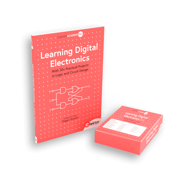
Dieses Bundle enthält das Buch Learning Digital Electronics mit über 20 praktischen Projekten in Logik- und Schaltungsdesign sowie ein 100-teiliges Starterkit – damit Sie sofort mit dem Bau von Logikschaltungen, Zählern, Displays und mehr beginnen können.
Learning Digital Electronics (Buch)
Dieses Buch ist ein praktischer Leitfaden zur digitalen Elektronik und behandelt die wesentlichen Komponenten moderner digitaler Systeme: Zahlensysteme, Logikgatter, Boolesche Algebra, kombinatorische und sequentielle Logik und mehr.
In über 20 strukturierten Projekten entwerfen und bauen Sie digitale Systeme mit realen Komponenten wie Logikgattern, Multiplexern, Decodern, Flip-Flops, Zählern und Schieberegistern. Die Projekte reichen von einfachen LED-Logikschaltungen bis hin zu digitalen Schlössern, Displaysystemen, Ampelsteuerungen und zeitbasierten Designs.
Ausgewählte Projekte führen in die Verwendung von Tools wie CircuitVerse zur Schaltungssimulation ein, während mehrere Designs Logikbausteine der 74HC-Serie verwenden, die häufig im digitalen Hardware-Prototyping verwendet werden.
Im Buch finden Sie:
Klare Darstellung von Zahlensystemen und Binärarithmetik
Grundlagen logischer Gatter und Implementierungen universeller Gatter
Schritt-für-Schritt-Projekte mit Flipflops, Zählern und Registern
Realwelt-Design mit Logikchips der 74HC-Serie
Techniken zum Entwurf kombinatorischer und sequentieller Systeme
Dieses Buch verfolgt einen designorientierten, anwendungsorientierten Ansatz für die digitale Elektronik – basierend auf funktionierenden Schaltungen, erprobter Logik und praktischen Experimenten.
Learning Digital Electronics (Kit)
Dieses Kit wurde speziell entwickelt, um das Buch "Learning Digital Electronics" zu ergänzen. Da alle benötigten Komponenten enthalten sind, können Sie jedes praktische Projekt im Buch direkt durchführen.
Inhalt des Kits
2x 74HC08 UND-Gatter-Chip
2x 74HC00 NAND-Gatter-Chip
1x 74HC86 XOR-Gatter-Chip
1x 555 Timer-Chip
1x 74HC161 Zähler-Chip
1x 74HC164 Schieberegister
1x CD4511 7-Segment-Decoder
1x CD4027 JK Flip-Flop
1x BC337 NPN-Transistor
1x KPS-5161 7-Segment-Display mit gemeinsamer Kathode
1x Lichtabhängiger Widerstand (LDR)
4x 10 KΩ Widerstände
8x 1 KΩ Widerstand
2x 47 KΩ Widerstände
1x 100 KΩ Widerstand
4x 2,7 KΩ Widerstände
1x 5,6 KΩ Widerstand
1x 150 KΩ Widerstand
1x 10 μF Kondensator
2x 0,01 μF Kondensator
2x 100 nF Kondensator
8x Kleine rote LED
1x Kleine grüne LED
1x Kleine orangefarbene LED
4x Drucktastenschalter
1x Aktiv-Summer
1x Batteriehalter für 3x AA-Batterien (Batterien nicht im Lieferumfang enthalten)
1x Steckplatine
40x Male-to-male Jumperkabel (Länge: 200 mm)
With 20+ Practical Projects in Logic and Circuit Design
This book is a practical guide to digital electronics, covering the essential components of modern digital systems: number systems, logic gates, Boolean algebra, combinational and sequential logic, and more.
Through more than 20 structured projects, you’ll design and build digital systems using real-world components such as logic gates, multiplexers, decoders, flip-flops, counters, and shift registers. The projects range from basic LED logic circuits to digital locks, display systems, traffic light controllers, and timing-based designs.
Selected projects introduce the use of tools such as CircuitVerse for circuit simulation, while several designs make use of 74HC-series logic devices, commonly used in digital hardware prototyping.
Inside, you’ll find:
Clear coverage of number systems and binary arithmetic
Logic gate fundamentals and universal gate implementations
Step-by-step projects using flip-flops, counters, and registers
Real-world design with 74HC-series logic chips
Techniques for designing combinational and sequential systems
This book takes a design-first, application-driven approach to digital electronics—built around working circuits, tested logic, and hands-on experimentation.
The Basics, New Ideas & Applications
Build digital electronics from the ground up—and take it all the way to practical circuits you can use.
This book guides you through the core principles of digital technology with a strongly hands-on approach. You’ll begin with the essentials: signals, devices for working with them, and what "logic 0" and "logic 1" mean in real hardware. Simple demonstration setups made from easy-to-find parts (LEDs, diodes, resistors, switches) help you see how logic behaves, making the theory click before you move on.
From there, you’ll explore a wide range of logic elements and how they’re implemented, including classic logic families such as TTL and CMOS. The fundamentals section covers the building blocks of digital systems: flip-flops, Schmitt triggers, registers, counters and dividers, encoders/ decoders, multiplexers/demultiplexers, plus A/D and D/A conversion and timing circuits.
Next, the book invites you into "new ideas" in digital electronics—universal logic elements, unconventional approaches (including thyristor-based and fractional logic), and creative logic functions that can inspire original designs.
Finally, a large, well-organized collection of application circuits turns knowledge into projects: electronic switches and selectors, pulse generators, PWM regulators, frequency multipliers/dividers, phase shifters, and digital filters.
Study it deeply, and you’ll gain not only understanding—but the ability to design and debug digital circuits independently.
With 20+ Practical Projects in Logic and Circuit Design
This book is a practical guide to digital electronics, covering the essential components of modern digital systems: number systems, logic gates, Boolean algebra, combinational and sequential logic, and more.
Through more than 20 structured projects, you’ll design and build digital systems using real-world components such as logic gates, multiplexers, decoders, flip-flops, counters, and shift registers. The projects range from basic LED logic circuits to digital locks, display systems, traffic light controllers, and timing-based designs.
Selected projects introduce the use of tools such as CircuitVerse for circuit simulation, while several designs make use of 74HC-series logic devices, commonly used in digital hardware prototyping.
Inside, you’ll find:
Clear coverage of number systems and binary arithmetic
Logic gate fundamentals and universal gate implementations
Step-by-step projects using flip-flops, counters, and registers
Real-world design with 74HC-series logic chips
Techniques for designing combinational and sequential systems
This book takes a design-first, application-driven approach to digital electronics—built around working circuits, tested logic, and hands-on experimentation.
MDP-M01 ist ein Display-Steuermodul, das mit einem 2,8-Zoll-TFT-Display ausgestattet ist. Das Display kann um 90 Grad gedreht werden, was für Benutzer bequem ist, um Daten und Wellenformen anzuzeigen. MDP-M01 kann Online-Anzeige und -Steuerung mit MDP-P906 Mini-Digital-Netzteilmodulen und anderen Modulen des MDP-Systems über drahtlose 2,4-GHz-Kommunikation realisieren und bis zu 6 Sub-Module gleichzeitig steuern.
Technische Daten
Bildschirmgröße
2,8" TFT
Bildschirmauflösung
240 x 320
Leistung
Micro-USB-Stromeingang oder Stromversorgung vom Submodul über dediziertes Stromkabel
Eingabe
DC 5 V/0,3 A
Andere Funktionen
Kann bis zu 6 Submodule steuernUpgrade der Formware über Micro USB
Abmessungen
107 x 66 x 13,6 mm
Gewicht
133 g
Included
1x MDP-M01 Smart Digital-Monitor
1x Kabel (2,5 mm Klinke auf Micro USB)
Downloads
User Manual v3.4
Firmware v1.32
Merkmale
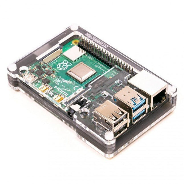
Nur mit Raspberry Pi 4 kompatibel
Ausschnitt im Deckel für 40x30mm Kühlkörper oder Lüfter SHIM
Superschlankes Profil
Vollständig HAT-kompatibel
Schützt Ihren geliebten Pi
Durchsichtige Ober- und Unterseite lassen Raspberry Pi 4 sichtbar
GPIO-Ausschnitt
Praktische, lasergravierte Anschlussbeschriftungen
Lässt alle Anschlüsse zugänglich
Hergestellt aus leichtem, hochwertigem, gegossenem Acryl
Großartig zum Hacken und Basteln!
Hergestellt in Sheffield, Großbritannien
Mit einem Gewicht von knapp über 50 Gramm ist das Gehäuse leicht und ideal für die Befestigung an jeder Oberfläche. Für die Montage oder Demontage sind keine Werkzeuge erforderlich. Die Abmessungen betragen: 99 × 66 × 15 mm.
Im Video unten sehen Sie eine Kurzanleitung zur Montage.
Das JOY-iT Armor Case BLOCK ist ein robustes Aluminiumgehäuse, das speziell für den Raspberry Pi 5 entwickelt wurde. Es bietet hervorragenden Schutz vor Hitze und Stößen und eignet sich daher für anspruchsvolle Umgebungen. Durch sein kompaktes Design benötigt es keinen zusätzlichen Platz und ermöglicht eine nahtlose Integration in bestehende Projekte.
Das Gehäuse verfügt über einen großen Kühlkörper, um die Kühleffizienz zu verbessern. Die Installation ist unkompliziert, da das Gehäuse mit vier Schrauben (im Lieferumfang enthalten) am Raspberry Pi befestigt wird.
Technische Daten
Material
CNC-gefräste Aluminiumlegierung
Kühlleistung
Leerlauf: ~39°CVolllast: ~75°C
Besonderheiten
Großer Kühlkörper, Schutz vor Stößen und Hitze bei gleichem Volumen wie ohne Gehäuse
Abmessungen (Oberseite)
69 x 56 x 15,5 mm
Abmessungen (Unterseite)
87 x 56 x 7,5 mm
The Arduino Uno is an open-source microcontroller development system encompassing hardware, an Integrated Development Environment (IDE), and a vast number of libraries. It is supported by an enormous community of programmers, electronic engineers, enthusiasts, and academics. The libraries in particular really smooth Arduino programming and reduce programming time. What’s more, the libraries greatly facilitate testing your programs since most come fully tested and working.
The Raspberry Pi 4 can be used in many applications such as audio and video media devices. It also works in industrial controllers, robotics, games, and in many domestic and commercial applications. The Raspberry Pi 4 also offers Wi-Fi and Bluetooth capability which makes it great for remote and Internet-based control and monitoring applications.
This book is about using both the Raspberry Pi 4 and the Arduino Uno in PID-based automatic control applications. The book starts with basic theory of the control systems and feedback control. Working and tested projects are given for controlling real-life systems using PID controllers. The open-loop step time response, tuning the PID parameters, and the closed-loop time response of the developed systems are discussed together with the block diagrams, circuit diagrams, PID controller algorithms, and the full program listings for both the Raspberry Pi and the Arduino Uno.
The projects given in the book aim to teach the theory and applications of PID controllers and can be modified easily as desired for other applications. The projects given for the Raspberry Pi 4 should work with all other models of Raspberry Pi family.
The book covers the following topics:
Open-loop and closed-loop control systems
Analog and digital sensors
Transfer functions and continuous-time systems
First-order and second-order system time responses
Discrete-time digital systems
Continuous-time PID controllers
Discrete-time PID controllers
ON-OFF temperature control with Raspberry Pi and Arduino Uno
PID-based temperature control with Raspberry Pi and Arduino Uno
PID-based DC motor control with Raspberry Pi and Arduino Uno
PID-based water level control with Raspberry Pi and Arduino Uno
PID-based LED-LDR brightness control with Raspberry Pi and Arduino Uno
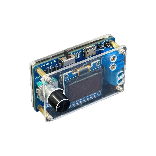
Das DIY Mini Digital-Oszilloskop-Kit (mit Gehäuse) ist ein einfach zu bauender Bausatz für ein kleines digitales Oszilloskop. Neben dem Netzschalter verfügt es nur über eine weitere Steuerung, einen Drehgeber mit eingebautem Druckknopf. Der Mikrocontroller des Kits ist vorprogrammiert. Das 0,96" OLED-Display hat eine Auflösung von 128 x 64 Pixel. Das Oszilloskop verfügt über einen Kanal, der Signale bis zu 100 kHz messen kann. Die maximale Eingangsspannung beträgt 30 V, die minimale Spannung beträgt 0 V.
Das Kit besteht aus Durchgangslochkomponenten (THT) und oberflächenmontierten Bauteilen (SMD). Daher erfordert der Zusammenbau des Bausatzes das Löten von SMD-Teilen, was einige Erfahrung im Löten erfordert.
Technische Daten
Vertikaler Bereich: 0 bis 30 V
Horizontaler Bereich: 100 µs bis 500 ms
Triggertyp: Auto, Normal und Single
Triggerflanke: Steigend und fallend
Triggerpegel: 0 bis 30 V
Run/Stop-Modus
Automatische Frequenzmessung
Stromversorgung: 5 V Micro-USB
10 Hz, 5 V Sinuswellenausgang
9 kHz, 0 bis 4,8 V Rechteckwellenausgang
Display: 0,96" OLED-Bildschirm
Abmessungen: 57 x 38 x 26 mm
Downloads
Documentation
Das Andonstar ADSM302 ist ein vielseitiges digitales Mikroskop mit integriertem 5-Zoll-LCD-Display und HDMI-Ausgang für gestochen scharfe Ansichten in Full-HD (1080p). Mit einem 3-Megapixel-Sensor, bis zu ~560-facher Vergrößerung und zwei einstellbaren LED-Lichtern macht es feinste Details sichtbar – ideal für Leiterplatten-Inspektionen, Lötarbeiten, Schmuck- oder Insekten-Analysen.
Features
5" verstellbarer LCD-Monitor mit einstellbarem Neigungswinkel
Hochauflösende Video- und Fotoaufnahme
Breiter Tisch mit bequemer Kopffreiheit
Schwerer, stabiler Metallständer mit hohem Gewicht
Hoher Hebebügel (26 cm)
Stufenlose Verstellräder für Fokus und Höhe
Tasten auf dem Monitor + Fernbedienung
AV-, USB- und HDMI-Ausgänge
SD-Kartenspeicher <32 GB
Technische Daten
Bildsensor
3 Megapixel HD-Sensor
Videoausgang
1080p Full HD (über HDMI)720p (über PC)
Videoformat
Echtzeit-Wiedergabe über HDMI ohne Aufnahme;MJPEG-Aufnahme über PC/Mac-Software
Vergrößerung
Bis zu 560 mal (HDMI-Monitor 22 Zoll)
Fotoauflösung
12M
Fotoformat
JPEG
Fokussierbereich
5 to 22 cm
Bildrate
Bis zu 30 f/s bei 600 Lux Helligkeit
Video-Schnittstelle
HDMI/AV
Speichermedium
microSD-Karte, bis zu 32 GB
PC-Unterstützung
Windows XP/7/8/10PC-Software mit MessungMacOS erfolgreich unter OSX mit OBS getestet
Stromversorgung
5 V DC
Beleuchtung
2 LEDs mit Stativ
Bildschirmgröße
5 Zoll (12,7 cm)
Standfußgröße
20 x 12 x 26,5 cm
Auflösung
Aufgenommene Fotos
4032 x 3024
3648 x 2736
3264 x 2448
2592 x 1944
2048 x 1536
640 x 480
1920 x 1080
1280 x 960
1280 x 720*
Videos
1920 x 1080
640 x 480*
* (USB mit Software)
Lieferumfang
1x Andonstar ADSM302 Digital-Mikroskop
1x Metallständer mit 2 LEDs
1x USB-Kabel
1x HDMI-Kabel
1x Adapter
1x AI-Fernbedienung
1x Handbuch
Downloads
Manual
Software