
Suchergebnisse für "analog OR circuit OR design OR 3"
-

Elektor Digital Introduction to Electronic Filters (E-book)
Learn RC and RL Filters with Hands-On Circuits and Simulation Introduction to Electronic Filters is your comprehensive guide to understanding, designing, and applying first-order electronic filters using resistors, capacitors, and inductors. Whether you are a student, maker, or educator, this book demystifies the theory behind RC and RL filters and bridges the gap between concepts and real-world applications through simulation and experimentation. From the basics of frequency response and phase shift to hands-on breadboard builds and Python-based simulations, this book offers a deeply practical learning experience. You will learn to analyse filters using Bode plots and phasors, and explore applications in audio tone shaping, sensor signal conditioning, noise reduction, and power supply filtering. As you progress, you’ll build, measure, simulate, and tune filters using modern tools like CircuitLab, Python, and the Analog Discovery 3. Each chapter includes thoughtfully crafted activities that reinforce learning by doing – designing filters for specific tasks, simulating dynamic behaviour, and observing how theory translates into performance. Inside you’ll find: A clear introduction to the fundamentals of electronic filters Detailed explanations of RC and RL filters, cutoff frequency, and phase Guided activities using both simulation and hardware tools Real-life applications in audio, sensors, power supplies, and more A beginner-friendly primer on Python and algebra for electronics Whether you’re working through simulations or experimenting with real components on your workbench, this book will help you develop a solid understanding of electronic filters and their role in practical circuits.
€ 32,95
Mitglieder: € 29,66
-

Elektor Publishing LTspice Essentials
An Introduction to Circuit Simulation LTspice, developed by Analog Devices, is a powerful, fast, and free SPICE simulator, schematic capture, and waveform viewer with a large database of components supported by SPICE models from all over the world. Drawing a schematic in LTspice is easy and fast. Thanks to its powerful graphing features, you can visualize the voltages and currents in a circuit, and also the power consumption of its components and much more. This book is about learning to design and simulate electronic circuits using LTspice. Among others, the following topics are treated: DC and AC circuits Signal diodes and Zener diodes Transistor circuits including oscillators Thyristor/SCR, diac, and triac circuits Operational amplifier circuits including oscillators The 555 timer IC Filters Voltage regulators Optocouplers Waveform generation Digital logic simulation including the 74HC family SPICE modeling LTspice is a powerful electronic circuit simulation tool with many features and possibilities. Covering them all in detail is not possible in a book of this size. Therefore, this book presents the most common topics like DC and AC circuit analysis, parameter sweeping, transfer functions, oscillators, graphing, etc. Although this book is an introduction to LTspice, it covers most topics of interest to people engaged in electronic circuit simulation. The book is aimed at electronic/electrical engineers, students, teachers, and hobbyists. Many tested simulation examples are given in the book. Readers do not need to have any computer programming skills, but it will help if they are familiar with basic electronic circuit design and operation principles. Readers who want to dive deeper can find many detailed tutorials, articles, videos, design files, and SPICE circuit models on the Internet. All the simulation examples used in the book are available as files at the webpage of this book. Readers can use these example circuits for learning or modify them for their own applications.
€ 39,95
Mitglieder: € 35,96
-

Elektor Publishing Introduction to Electronic Filters
Learn RC and RL Filters with Hands-On Circuits and Simulation Introduction to Electronic Filters is your comprehensive guide to understanding, designing, and applying first-order electronic filters using resistors, capacitors, and inductors. Whether you are a student, maker, or educator, this book demystifies the theory behind RC and RL filters and bridges the gap between concepts and real-world applications through simulation and experimentation. From the basics of frequency response and phase shift to hands-on breadboard builds and Python-based simulations, this book offers a deeply practical learning experience. You will learn to analyse filters using Bode plots and phasors, and explore applications in audio tone shaping, sensor signal conditioning, noise reduction, and power supply filtering. As you progress, you’ll build, measure, simulate, and tune filters using modern tools like CircuitLab, Python, and the Analog Discovery 3. Each chapter includes thoughtfully crafted activities that reinforce learning by doing – designing filters for specific tasks, simulating dynamic behaviour, and observing how theory translates into performance. Inside you’ll find: A clear introduction to the fundamentals of electronic filters Detailed explanations of RC and RL filters, cutoff frequency, and phase Guided activities using both simulation and hardware tools Real-life applications in audio, sensors, power supplies, and more A beginner-friendly primer on Python and algebra for electronics Whether you’re working through simulations or experimenting with real components on your workbench, this book will help you develop a solid understanding of electronic filters and their role in practical circuits.
€ 39,95
Mitglieder: € 35,96
-

Elektor Bundles Practical Electronics Crash Course (Bundle)
Der Einstieg in die Elektronik ist nicht so schwierig, wie Sie vielleicht denken. Mit diesem Bundle (Buch + Kit) können Sie durch verschiedene Experimente die wichtigsten Konzepte der Elektro- und Elektroniktechnik auf spielerische Weise erforschen und erlernen. Sie erlernen Elektronik praxisnah, ohne sich auf komplizierte Fachsprache und lange Berechnungen einzulassen. Daher werden Sie bald Ihre eigenen Projekte erstellen. Das Kit enthält die erforderlichen Komponenten, um die meisten detaillierten Beispiele des Buches auf einem Steckbrett zu bauen und sie in der Realität auszuprobieren. Das Kit kann selbstverständlich auch ohne das Buch zum Aufbau anderer Schaltkreise und zur Durchführung eigener Experimente verwendet werden. Inhalt des Kits 1x 39 Ω, 1 W Widerstand 1x 47 Ω Widerstand 1x 180 Ω Widerstand 1x 330 Ω Widerstand 3x 1 kΩ Widerstand 1x 2,2 kΩ Widerstand 1x 3,9 kΩ Widerstand 1x 6,8 kΩ Widerstand 1x 10 kΩ Widerstand 1x 15 kΩ Widerstand 1x 22 kΩ Widerstand 1x 33 kΩ Widerstand 1x 47 kΩ Widerstand 1x 56 kΩ Widerstand 1x 82 kΩ Widerstand 1x 120 kΩ Widerstand 1x 680 kΩ Widerstand 2x 100 kΩ Widerstand 1x 10 kΩ Trimmer 1x 10 kΩ Linearpotentiometer 1x 100 kΩ Linearpotentiometer 1x LDR 1x 1 nF Keramikkondensator 2x 10 nF Keramikkondensator 1x 100 nF Keramikkondensator 1x 1 µF, 25 V Aluminium-Elektrolytkondensator 2x 10 µF, 25 V Aluminium-Elektrolytkondensator 1x 100 µF, 25 V Aluminium-Elektrolytkondensator 1x 470 µF, 25 V Aluminium-Elektrolytkondensator 1x 1000 µF, 25 V Aluminium-Elektrolytkondensator 1x RGB-LED, Common-Cathode (CC) 1x 1N4148 Kleinsignaldiode 1x 1N4733A 5,1 V, 1 W Zenerdiode 3x LED, rot 2x BC337 NPN-Transistor 1x IRFZ44N N-Kanal-MOSFET 2x NE555-Timer 1x LM393-Komparator 1x 74HCT08 Quad-AND-Gatter 3x Tastschalter 2x SPDT-Schalter 1x Relais, SPDT, 9 VDC 1x Aktiver Summer 1x Passiver Summer 50 cm Massivdraht, 16 AWG, ohne Mantel 2x PP3 9 V Batterieclip 1x Steckbrett 20x Überbrückungskabel Dieses Bundle enthält: Practical Electronics Crash Course Kit (Wert: 45 €) Buch: Practical Electronics Crash Course (Einzelpreis: 45 €)
€ 89,95€ 69,95Bestpreis
-
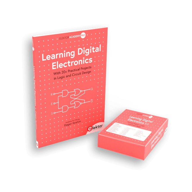
Elektor Bundles Learning Digital Electronics (Bundle)
Digitale Elektronik praxisnah meistern! Dieses Bundle enthält das Buch Learning Digital Electronics mit über 20 praktischen Projekten in Logik- und Schaltungsdesign sowie ein 100-teiliges Starterkit – damit Sie sofort mit dem Bau von Logikschaltungen, Zählern, Displays und mehr beginnen können. Learning Digital Electronics (Buch) Dieses Buch ist ein praktischer Leitfaden zur digitalen Elektronik und behandelt die wesentlichen Komponenten moderner digitaler Systeme: Zahlensysteme, Logikgatter, Boolesche Algebra, kombinatorische und sequentielle Logik und mehr. In über 20 strukturierten Projekten entwerfen und bauen Sie digitale Systeme mit realen Komponenten wie Logikgattern, Multiplexern, Decodern, Flip-Flops, Zählern und Schieberegistern. Die Projekte reichen von einfachen LED-Logikschaltungen bis hin zu digitalen Schlössern, Displaysystemen, Ampelsteuerungen und zeitbasierten Designs. Ausgewählte Projekte führen in die Verwendung von Tools wie CircuitVerse zur Schaltungssimulation ein, während mehrere Designs Logikbausteine der 74HC-Serie verwenden, die häufig im digitalen Hardware-Prototyping verwendet werden. Im Buch finden Sie: Klare Darstellung von Zahlensystemen und Binärarithmetik Grundlagen logischer Gatter und Implementierungen universeller Gatter Schritt-für-Schritt-Projekte mit Flipflops, Zählern und Registern Realwelt-Design mit Logikchips der 74HC-Serie Techniken zum Entwurf kombinatorischer und sequentieller Systeme Dieses Buch verfolgt einen designorientierten, anwendungsorientierten Ansatz für die digitale Elektronik – basierend auf funktionierenden Schaltungen, erprobter Logik und praktischen Experimenten. Learning Digital Electronics (Kit) Dieses Kit wurde speziell entwickelt, um das Buch "Learning Digital Electronics" zu ergänzen. Da alle benötigten Komponenten enthalten sind, können Sie jedes praktische Projekt im Buch direkt durchführen. Inhalt des Kits 2x 74HC08 UND-Gatter-Chip 2x 74HC00 NAND-Gatter-Chip 1x 74HC86 XOR-Gatter-Chip 1x 555 Timer-Chip 1x 74HC161 Zähler-Chip 1x 74HC164 Schieberegister 1x CD4511 7-Segment-Decoder 1x CD4027 JK Flip-Flop 1x BC337 NPN-Transistor 1x KPS-5161 7-Segment-Display mit gemeinsamer Kathode 1x Lichtabhängiger Widerstand (LDR) 4x 10 KΩ Widerstände 8x 1 KΩ Widerstand 2x 47 KΩ Widerstände 1x 100 KΩ Widerstand 4x 2,7 KΩ Widerstände 1x 5,6 KΩ Widerstand 1x 150 KΩ Widerstand 1x 10 μF Kondensator 2x 0,01 μF Kondensator 2x 100 nF Kondensator 8x Kleine rote LED 1x Kleine grüne LED 1x Kleine orangefarbene LED 4x Drucktastenschalter 1x Aktiv-Summer 1x Batteriehalter für 3x AA-Batterien (Batterien nicht im Lieferumfang enthalten) 1x Steckplatine 40x Male-to-male Jumperkabel (Länge: 200 mm)
€ 69,95€ 59,95Bestpreis
-
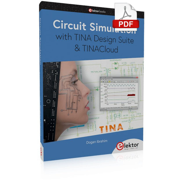
Elektor Digital Circuit Simulation with TINA Design Suite & TINACloud (E-book)
TINA Design Suite is a professional, powerful and affordable circuit simulator. It is a circuit designer and PCB design software package for analysing, designing, and real-time testing of analogue, digital, IBIS, VHDL, Verilog, Verilog AMS, SystemC, MCU, and mixed electronic circuits and their PCB layouts. In this book, top-selling Elektor author, Prof. Dr. Dogan Ibrahim aims to teach the design and analysis of electrical and electronic circuits and develop PCB boards using both TINA and TINACloud. The book is aimed at electrical/electronic engineers, undergraduate electronic/electrical engineering students at technical colleges and universities, postgraduate and research students, teachers, and hobbyists. Many tested and working simulation examples are provided covering most fields of analogue and digital electrical/electronic engineering. These include AC and DC circuits, diodes, zener diodes, transistor circuits, operational amplifiers, ladder diagrams, 3-phase circuits, mutual inductance, rectifier circuits, oscillators, active and passive filter circuits, digital logic, VHDL, MCUs, switch-mode power supplies, PCB design, Fourier series, and spectrum. Readers do not need to have any programming experience unless they wish to simulate complex MCU circuits.
€ 39,95
Mitglieder: € 35,96
-

Red Pitaya Red Pitaya STEMlab 125-14 PRO Gen 2 Starter Kit (inkl. Buch)
Dieses Bundle enthält das Red Pitaya STEMlab 125-14 PRO Gen 2 Starter Kit und das neue Buch "Experimenting with Red Pitaya STEMlab Gen 2". Das Red Pitaya STEMlab 125-14 PRO Gen 2 Starter Kit ist eine leistungsstarke und flexible Plattform für Signalverarbeitung, Datenerfassung und elektronische Messanwendungen. Dieses Kit wurde für Ingenieure, Entwickler, Forscher und Dozenten konzipiert und bietet alles, was für den Einstieg in die Entwicklung fortschrittlicher Mess- und Steuerungssysteme erforderlich ist. Das Herzstück des Kits ist das STEMlab 125-14 PRO Gen 2-Board, eine verbesserte und ultraleichte Entwicklungsplatine. Angetrieben vom Xilinx Zynq-7010 SoC mit 512 MB RAM kombiniert es die Programmierbarkeit eines FPGAs mit der Rechenleistung eines ARM-Prozessors, um leistungsstarke Messtechnik und kundenspezifische Signalverarbeitungslösungen zu ermöglichen. Das Board bietet eine 14-Bit-ADC- und DAC-Auflösung, eine Abtastrate von 125 MS/s, einen Eingangsbereich von ±20 V und eine Bandbreite von bis zu 60 MHz. Dank seines verbesserten rauscharmen analogen Frontends, der USB-C-Konnektivität und des kompakten Designs eignet es sich für anspruchsvolle Anwendungen wie HF-Entwicklung, Radarsysteme, Photonikforschung, Software-Defined Radio (SDR) und industrielle Automatisierung. Das Starter Kit enthält alles notwendige Zubehör für den sofortigen Einsatz: eine microSD-Karte mit vorinstalliertem Betriebssystem, ein Netzteil, ein Ethernet-Kabel für den Fernzugriff, zwei 100-MHz-Oszilloskop-Messspitzen sowie SMA-zu-BNC-Adapter für flexible Signalanschlüsse. Das Red Pitaya STEMlab 125-14 PRO Gen 2 Starter Kit ist eine hervorragende Plattform für Rapid Prototyping, FPGA-Entwicklung, Messtechnik und fortgeschrittene Elektronikversuche. Features 14-Bit-ADC- und DAC-Auflösung Abtastrate: 125 MS/s Eingangsspannungsbereich: ±20 V Bandbreite: Bis zu 60 MHz Xilinx Zynq-7010 SoC (FPGA + ARM-Prozessor) 512 MB RAM Rauscharme analoge Front- und Backends Anwendungen HF-Entwicklung und -Test Radar- und drahtlose Systeme Software Defined Radio (SDR) Photonik und optische Forschung Industrielle Automatisierungs- und Steuerungssysteme Signalanalyse und -instrumentierung Schnelles Prototyping elektronischer Bauteile Messsysteme Technische Daten Prozessor Dual-Core ARM Cortex-A9 FPGA AMD Xilinx Zynq-7010 SoC RAM 512 MB (4 Gb) Speicher microSD-Karte (bis zu 32 GB) Betriebssystem Linux-basiertes Red Pitaya OS ADC-Auflösung 14 Bit DAC Auflösung 14 Bit Bandbreite 60 MHz (DC) Abtastrate 125 MS/s Analoge Eingangskanäle 2 Analoge Ausgangskanäle 2 Eingangsspannungsbereich ±1 V (LV) / ±20 V (HV) Eingangsimpedanz 1 MΩ / 10 pF Ausgangsspannungsbereich ±1 V Ethernet 1x Gigabit Ethernet (RJ45) USB 2x USB-C 2.0 (für Stromversorgung und Konsole) Digitale Ein-/Ausgänge 16x GPIO (3,3 V) Kommunikationsschnittstellen I²C, SPI, UART, CAN Stromversorgung 5 V/3 A über USB-C Abmessungen 106,8 x 60,0 x 17,9 mm Lieferumfang 1x Red Pitaya STEMlab 125-14 PRO Gen 2 Board 2x 100-MHz-Oszilloskop-Tastköpfe 2x SMA-zu-BNC-Adapter 1x microSD-Karte mit vorinstalliertem Betriebssystem 1x USB-C-Netzteil 1x Ethernet-Kabel Downloads Documentation Schematics Buch: Experimenting with Red Pitaya STEMlab Gen 2 Mit diesem neuen Buch geht Red Pitaya über ein vielseitiges Board hinaus – es wird zu einem leistungsstarken Laborinstrument für präzise Messungen, Analysen und Steuerungen. Von den Grundlagen der Entwicklung elektronischer Projekte über Überwachung, Regelung und Design bis hin zu Tests führt Sie dieses Buch Schritt für Schritt durch alles, was Sie wissen müssen, um das volle Potenzial der Red Pitaya-Hardware und -Software auszuschöpfen. Das Buch stellt Echtzeitprojekte auf FPGA-Basis vor, die auf einem PC mit der Vivado-Umgebung entwickelt und anschließend zur Ausführung und zum Testen auf die Red Pitaya übertragen werden. Sie lernen mehr über gesteigerte Leistung, erweiterte I/O-Möglichkeiten, verbesserte FPGA-Funktionen sowie fortschrittliche Konnektivitätsoptionen, die neue Möglichkeiten für präzise Messungen, Überwachung und Steuerung in Ihren Embedded-Anwendungen eröffnen. Im Buch entdecken Sie: Einen tiefgehenden Einblick in die Red Pitaya-Architektur und das Hardware-Design Elektronische Experimente mit Red Pitaya für Mess- und Überwachungsanwendungen Praxisnahe Projekte mit der Programmiersprache Python Praktische Anleitungen zur FPGA-Programmierung mit Red Pitaya Red Pitaya FPGA-Projekte mit Verilog HDL in der Vivado IDE Die praxisorientierte Entwicklung elektronischer Projekte inklusive Messung und Tests Schritt-für-Schritt-Beispiele, die Theorie und reale Umsetzung miteinander verbinden Ganz gleich, ob Sie eigene elektronische Schaltungen entwerfen, Werkzeuge zur Signalanalyse entwickeln oder Echtzeit-Steuerungs- und Überwachungssysteme erstellen – dieses Buch vermittelt Ihnen das nötige Wissen und die Sicherheit, um die Red Pitaya-Plattform vollständig zu verstehen und individuell anzupassen.
€ 799,00
Bestpreis
-

FNIRSI FNIRSI 2D15P (3-in-1) 2-Kanal Oszilloskop (100 MHz) + Multimeter + Signalgenerator
Das FNIRSI 2D15P ist ein kompaktes 3-in-1 Prüfgerät, das ein 2-Kanal-Oszilloskop, ein True-RMS-Multimeter und einen Funktionsgenerator in einem Gerät vereint. Mit einem 4,3-Zoll-kapazitiven Touchscreen, 100 MHz Bandbreite, 500 MSa/s Abtastrate und einer Aufnahmegeschwindigkeit von bis zu 1200 Bildern pro Sekunde eignet es sich ideal für schnelle Fehlersuche, Signalanalyse und Elektroniktests. Features Zweikanal-Eingang (100 MHz Einkanal, 50 MHz Zweikanalbetrieb) Wählbare Speichertiefen Bandbreitenbegrenzung: 20 MHz Graustufen- und Farbtemperaturvisualisierung Mathematische Operationen (Addition, Subtraktion, Multiplikation, Division usw.) XY-Modus und unendliche Nachleuchtdauer Cursorfunktion und 13 automatische Messungen Auto / Normal / Single Triggermodi True-RMS-Multimeter (19.999 Counts) 10-MHz-DDS-Signalgenerator Technische Daten Allgemein Display 4,3" IPS-Touchscreen (kapazitiv) Bedienung Touch + Drehknopf + Tasten Laden USB-C (12 V/1 A Fast Charging) Akku 5000 mAh Lithium-Akku Abmessungen 19,6 x 12,9 x 5,7 cm Gewicht 1,1 kg Oszilloskop Kanäle 2 Analoge Bandbreite 100 MHz Abtastrate 500 MSa/s Speichertiefe 10 kΩ, 100 kΩ, 1 MΩ Eingangsimpedanz 1 MΩ Zeitbasisbereich 5 ns – 50 s Vertikale Empfindlichkeit 10 mV – 10 V/div Maximale Eingangsspannung 800 V (x10-Sonde) Triggermodus Auto, Normal, Single Triggertyp Ansteigend, Abfallend, Beide Flanken Kopplung AC/DC Nachlaufzeit min / 2s / 5s / 10s / 20s / 50s / ∞ Mathematik Operationen Ja Wellenformerfassung Ja Wellenformexport Ja Cursormessung Ja Multimeter Gleichspannung 1.9999V / 19.999V / 199.99V / 1000V Wechselspannung 1.9999V / 19.999V / 199.99V / 750.0V Gleichstrom 19.999mA / 199.99mA / 1.9999A / 9.999A Wechselstrom 19.999mA / 199.99mA / 1.9999A / 9.999A Widerstand 19.999MΩ / 1.9999MΩ / 199.99KΩ / 19.999KΩ / 1.9999KΩ / 199.99Ω Kapazität 999.9uF / 99.99uF / 9.999uF / 999.9nF / 99.99nF / 9.999nF / 9.999mF / 99.99mF Diode Ja Durchgang Ja Signalgenerator Kanäle 1 Frequenz 0–10 MHz Amplitude 0,1–3,0 Vpp Tastverhältnis 0–100% Lieferumfang 1x FNIRSI 2D15P Oszilloskop 2x P6100 Oszilloskop-Tastköpfe 1x Multimeter-Sonde 1x Krokodilklemmensonde 1x USB-Datenkabel 1x Manual Downloads Manual Firmware V2.7.0.7
€ 209,00€ 179,95Bestpreis
-

Elektor Bundles 555-Timer-Projekte (Bundle)
Dieses Bundle befasst sich mit der Entwicklung von Projekten, die auf dem 555-Timer-IC basieren. Das Buch enthält über 45 vollständig getestete und dokumentierte Projekte. Zusammen mit dem Kit, das mehr als 130 durchkontaktierte Bauteile enthält, können Sie alle beschriebenen Projekte auf einem Breadboard nachbauen. Der Aufbau macht es auch einfach, die Projekte zu modifizieren und mit ihnen zu experimentieren. Über 45 Projekte für den legendären 555-Chip (und den 556, 568) Einige der Projekte im Buch sind: Abwechselnd blinkende LEDs Veränderung der Blinkrate von LEDs Touchsensor-Ein/Aus-Schalter Ein-/Ausschaltverzögerung Lichtabhängiger Ton Dunkel-Hell-Lichtschalter Tonburst-Generator Langzeit-Timer Lauflichter LED-Roulette-Spiel Ampelsteuerung Durchgangsprüfer Elektronisches Schloss Kontaktentprellung für Schalter Spielzeug-Elektronikorgel Mehrfachsensor-Alarmsystem Metronom Spannungsmultiplizierer Elektronischer Würfel 7-Segment-Display-Zähler Motorsteuerung 7-Segment-Display-Würfel Elektronische Sirene Verschiedene andere Projekte Inhalt des Kits Widerstände 1x 15 kΩ 1x 68 kΩ 2x 47 kΩ 1x 82 kΩ 2x 820 Ω 1x 8,2 kΩ 3x 10 kΩ 1x 1,8 kΩ 1x 6,8 kΩ 14x 2,2 kΩ 10x 680 Ω 1x 27 kΩ 1x 5,6 kΩ 1x 560 kΩ 1x 4,7 kΩ 1x 3,3 kΩ 3x 33 kΩ 1x 36 kΩ 2x 100 kΩ 5x 1 kΩ 1x 3,9 kΩ 2x 56 kΩ 2x 12 kΩ 1x 10 kΩ Potentiometer 1x 1 MΩ Potentiometer 2x 50 kΩ Potentiometer 3x 20 kΩ Potentiometer 1x 10 kΩ Potentiometer 1x 10 kΩ Potentiometer 1x 50 kΩ Potentiometer 1x 100 kΩ Potentiometer 1x 50 kΩ Potentiometer Kondensatoren 1x 0,33 μF 1x 1 μF 1x 10 nF 1x 22 nF 1x 47 nF 1x 100 nF 1x 10 μF electrolytisch 1x 33 μF electrolytisch 2x 100 μF electrolytisch LEDs 10x 5 mm rote LED 10x 3 mm rote LED 3x 3 mm gelbe LED 3x 3 mm grüne LED 1x 7-Segment-LED mit gemeinsamer Kathode Halbleiter 3x 555-Timer 1x CD4017 Counter 1x CD4026 Counter 1x CD4011 NAND-Gate 4x 1N4148 Diode 1x IRFZ46N MOSFET 1x Thermistor 1x Lichtabhängiger Widerstand (LDR) Sonstiges 1x Passiver Summer 1x Aktiver Summer 1x SG90-Servo 1x 8 Ω Mini-Lautsprecher 1x 9 V DC Bürstenmotor 1x 5 V Relais 1x 9 V Batterieclip 7x Drucktastenschalter 1x Breadboard 1x Breadboard-Überbrückungskabel
€ 69,95€ 54,95Bestpreis
-

Elektor Digital LTspice Essentials (E-book)
An Introduction to Circuit Simulation LTspice, developed by Analog Devices, is a powerful, fast, and free SPICE simulator, schematic capture, and waveform viewer with a large database of components supported by SPICE models from all over the world. Drawing a schematic in LTspice is easy and fast. Thanks to its powerful graphing features, you can visualize the voltages and currents in a circuit, and also the power consumption of its components and much more. This book is about learning to design and simulate electronic circuits using LTspice. Among others, the following topics are treated: DC and AC circuits Signal diodes and Zener diodes Transistor circuits including oscillators Thyristor/SCR, diac, and triac circuits Operational amplifier circuits including oscillators The 555 timer IC Filters Voltage regulators Optocouplers Waveform generation Digital logic simulation including the 74HC family SPICE modeling LTspice is a powerful electronic circuit simulation tool with many features and possibilities. Covering them all in detail is not possible in a book of this size. Therefore, this book presents the most common topics like DC and AC circuit analysis, parameter sweeping, transfer functions, oscillators, graphing, etc. Although this book is an introduction to LTspice, it covers most topics of interest to people engaged in electronic circuit simulation. The book is aimed at electronic/electrical engineers, students, teachers, and hobbyists. Many tested simulation examples are given in the book. Readers do not need to have any computer programming skills, but it will help if they are familiar with basic electronic circuit design and operation principles. Readers who want to dive deeper can find many detailed tutorials, articles, videos, design files, and SPICE circuit models on the Internet. All the simulation examples used in the book are available as files at the webpage of this book. Readers can use these example circuits for learning or modify them for their own applications.
€ 32,95
Mitglieder: € 29,66


-
, von Udo Bormann Electronics Projects Archive for Engineers, Makers & Education
Access thousands of electronics projects, Arduino tutorials, audio designs, and power supply circuits with Elektor Classics USB sticks. Designed for younger engineers, university professors, electronics educators,...
-
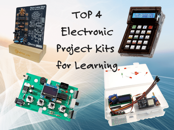
, von Udo Bormann Die 4 besten Elektor-Elektronik-Projektbaukästen zum Lernen und Entwickeln von Fertigkeiten
Entdecken Sie vier der spannendsten Elektronikbausätze von Elektor - von IoT und Arduino bis hin zu Retro-Logik und Bewegungssteuerung. Egal, ob Sie gerade erst anfangen...
