
Suchergebnisse für "dragino OR lora OR iot OR development OR kit OR 868 OR mhz"
-

Elektor Labs Elektor Rauscharmes Labornetzteil
Das rauscharme Labornetzteil von Elektor ist ein vollständig analoges, einstellbares, symmetrisches Gerät mittlerer Leistung, das ohne Schalt- oder digitale Komponenten auskommt. Es bietet eine Ausgangsspannung, die zwischen 0 V und ±22 V einstellbar ist, sowie einen Ausgangsstrom, der von 0 A bis 1 A eingestellt werden kann. Da auf jegliche Art von Schalttechnik verzichtet wird, liefert das Design extrem geringes Rauschen. Zur Anzeige beider Ausgangsspannungen und -ströme werden vier kleine analoge Einbauinstrumente mit Drehspulmesswerk verwendet. Die meisten modernen Labornetzgeräte und AC-Adapter arbeiten mit Schaltnetzteiltechnik. Selbst die besten Ausführungen weisen zwangsläufig hochfrequente Restwelligkeit und andere Schaltartefakte am Ausgang auf, die die Prüfung empfindlicher analoger Schaltungen stören und Messungen kleiner Signale beeinträchtigen können. Um dieses Problem zu vermeiden, setzt dieses Konzept auf ein vollständig analoges Netzgerät. Obwohl es weniger effizient ist als vergleichbare Schaltnetzteile, spielt die geringere Effizienz beim Einsatz auf dem Prüfstand kaum eine Rolle und sorgt für sauberere und zuverlässigere Messergebnisse. Da viele analoge Schaltungen eine symmetrische Versorgung benötigen, liefert dieses Design positive und negative Ausgangsspannungen gleicher Höhe. Eine geringfügige Nachjustierung ist möglich, um eventuelle Ungleichgewichte auszugleichen. Selbstverständlich ist auch eine einstellbare Strombegrenzung integriert. Das Kit enthält die für den Aufbau des Netzteils erforderlichen Komponenten, mit Ausnahme der Transformatoren. Technische Daten Ausgangsspannung 0…+22 V, 0, −22 V Ausgangsstrom 0…+1 A, 0…−1 A Rauschen −85 dBV (bei 0,95 A/20 V, B = 22 kHz) −84 dBV (bei 0,95 A/20 V, B > 500 kHz) Restwelligkeit 50 µVRMS (bei 950 mA/20 V, B = 22 kHz, hauptsächlich 100-Hz-Anteil) Lieferumfang 3x Platinen: Regler (PCB-1), Netzfilter (PCB-2) und Transformator (PCB-3) Alle Bauteile mit Ausnahme der Netztransformatoren 4x Drehspulmesswerke Zusätzliche Teile für die Verdrahtung (Drähte, Bananenbuchsen, Kaltgeräte-Netzmodul usw.) Nicht enthalten Die drei Netztransformatoren Ein Gehäuse Stückliste Für die Spannungsregler-Platine (240386-1) Widerstände (250 mW, 1%) R1 = 12 Ω R2, R8, R37, R62 = 1 MΩ R3, R7, R10, R13, R17, R20, R22, R30, R35, R42, R45, R47, R55, R60 = 100 Ω, 600 mW R4, R5 = 4.7 kΩ R6 = 100 kΩ R9, R12, R14, R36, R38, R39, R61, R63, R66, R72, R78, R79 = 10.0 kΩ, 600 mW R11 = 9.76 kΩ, 600 mW R15, R40 = 44.2 kΩ, 600 mW R16, R41, R77 = 1 kΩ R18, R43 = 1.5 kΩ, 1 W, 5% R19, R44 = 470 Ω, 1 W, 5% R21, R46 = 330 Ω, 600 mW R23, R24, R48, R49 = 1.0 Ω, 1 W R25, R50 = 1 kΩ, 1 W, 5% R26, R28, R51, R53 = 1.000 kΩ 0.1%, 15 ppm/C R27, R29, R52, R54 = 10.00 kΩ 0.1%, 15 ppm/C R31, R56 = 1.2 kΩ, 1 W, 5% R32, R57 = 47 kΩ R33, R58 = 270 Ω R34, R59 = 27 kΩ R64, R69 = 12.0 kΩ R65 = 3.0 kΩ, 600 mW R67, R80 = 470 Ω, 600 mW R68, R70 = 6.8 kΩ, 600 mW R71 = 30.0 kΩ,, 600 mW R73, R74, R75, R76 = 10 MΩ P1, P2, P3 = 10 kΩ, 200 mW, 20%, potentiometer, 1 turns, single, lin., panel mount P4, P5 = 500 Ω, 500 mW, 10%, trimmer, 25 turns, 3296Y-1-501LF Bourns P6, P7 = 10 kΩ, 500 mW, 10%, trimmer, 25 turns, 3296Y-1-501LF Bourns Kondensatoren C1 = 100 nF, 50 V, 10%, ceramic X7R, LS 5 mm C2, C3, C6, C7, C30 = 10 µF, 63V, 20%, LS 2.5 mm, 3000hours@105°C C4, C5, C8, C9, C13, C14, C18, C19, C23, C24, C28, C29, C31, C32, C38, C39 = 100 nF, 250 V, 10%, PET, LS 7.5 mm C10, C20 = 47 nF, 100 V, 5%, PET, LS 5 mm C11, C21 = 10 nF, 100 V, 5%, PET, LS 5 mm C12, C22 = 220 µF, 35 V, 20%, 0.024 Ω, LS2.5/3.5 mm, Ir 3.4 A, 2000hours@125°C, polymer C15, C25 = 120 µF, 50 V, 20%, ESR 0.02 Ω, Diam. 10 mm max., LS 5 mm C16, C26 = 15 nF, 100 V, 5%, PET, LS 5 mm C17, C27 = 47 nF, 100 V, 5%, PET, LS 5 mm C33, C34 = 22 µF, 50 V, 20%, LS 2 mm, 10000 hours @ 105°C C35, C36, C44, C45 = 1 µF, 100 V, 10%, LS 5 mm, ceramic X7R C37 = 100 uF, 50 V, 20%. LS 3.5 mm C40, C41, C42, C43, C46, C47, C48, C49 = 1000 µF, 50 V, 20%, LS 5/7.5 mm, Ir 3.32 A, 10000hours@105°C, D 16 mm C50, C51, C52, C53 = 47 nF, 100 V, 10%, ceramic X7R, LS 5 mm Induktivitäten L1, L2 = 4.7 µH, 3.2 A, 0.033 Ω, LS 5 mm, RLB0914-4R7ML Bourns L3 = Commom mode choke, 14.5 mH, 3 A, SSRH24NH-30145 Kemet Halbleiter D1, D2, D3, D4, D5, D9, D10, D11, D15 = BAT85, DO-34 D6, D7, D12, D13 = SR560, DO-201AD D8, D14, D16 = 1N4148, DO-35 D17 = Zenerdiode, 5.6 V, 0.5 W, DO-41 D18, D19 = 1N4004, DO-41 D20, D21 D22, D23 = V30100CI-M3/P, dual common cathode, TO-220 D24 = Zener diode, 30 V, 1 W, DO-41 LED1, LED2 = LED, red, T-1 (3 mm) LED3, LED4 = LED, green, T-1 (3 mm) TVS1, TVS2 = BZW50-33B, R6 T1, T2, T4 = BC337.25, TO-92 T3 = NJW0302G, TO-3P T5, T6, T8 = BC327.25, TO-92 T7 = NJW0281G, TO-3P T9 = BD139, TO-126 (SOT-32) IC1 = LM334Z, TO-92 IC2 = LM4040AIZ-5.0/NOPB, TO-92 (TO-226AA-3) IC3, IC4 = OPA2992IDR, SOIC-8 IC5, IC6 = OPA4992IDR, SOIC-14 IC7 = OPA992IDBVR, SOT-23-5 IC8 = LM339N, DIP-14 IC9 = LM317, TO-220 IC10 = LM337, TO-220 Sonstiges F1, F2 = 5×20 mm fuse, 1.6 A, fast acting HS1, HS2 = Heatsink MC33271 (for T3/T7), 2.7°C/W, PCB mount, height 63.5 mm K1, K4 = 3-way screw terminal block, LS 3.5 mm, max. 1.5 mm² K2, K3 = 3-way screw terminal block, LS 3.5 mm, max. 1 mm² M1, M3 = Moving coil meter, Range 30 V, type 91C4, 45×45 mm M2, M4 = Moving coil meter, Range 1 A, type 91C4, 45×45 mm² RE1 = Relay DPDT,5V, UA2-5NU Verschiedenes 3× 3-way screw terminal block, LS 3.5 mm, max. 1 mm² (for P1, P2, P3) 4× Pin header, 1×2, vertical, pitch 2.54 mm (for LED1, LED2, LED3, LED4) 4× Pin socket, 1×2, vertical. pitch 2.54 mm (for LED1, LED2, LED3, LED4) 2× Heatsink FK222SA220, 20°C/W, PCB mount (for IC9 & IC10) 2× Mica thermal pad for TO-220, 12×18×0.05 mm (for IC9 & IC10) 2× Insulating bushing IB 6, TO-220 (for IC9 & IC10) 2× Ceramic thermal pad, 23×20×2 mm (for T3 & T7) 2× PCB Fuse Holder, for 5×20 mm fuse, 10 A (for F1, F2) 2× Cover for PCB Fuse Holder, transparent (for F1, F2) 2× 2-way screw terminal block, LS 3.5 mm, max. 1 mm² (for M1 & M3) 2× 2-way screw terminal block, LS 3.5 mm, max. 1.5 mm² (for M2 & M4) 8× M3 solder lug, thickness 0.35 mm (for M1…M4) M4 solder lug, thickness 0.35 mm (to connect 4 mm banana connectors) Screened cable, 1 pair, 2×24 AWG/0.22 mm², 1 m (for P1, P2 & P3) IC socket, DIP, 14 contacts (for IC8) M3 washer, plain, steel M3 screw, 16 mm, steel, pan head M3 nut M3 spring washer 50 mm M3 standoff, steel, male-female 12 mm M3 standoff, steel, male-female 10 mm M3 standoff, steel, male-female M3 screw, 8 mm, steel, pan head Für die Netzfilter-Platine (240386-2) Widerstand R1 = 220 kΩ, 1 W, 500 V, 5% Kondensatoren C1, C2 = 470 nF, 305 VAC, Class X2, 11 × 27 mm max., LS 15/22.5 mm C3, C4, C5, C6 = 2.2 nF, 300 VAC, Class Y2, 13 × 4 mm, LS 10 mm, PP Induktivitäten L1, L2 = Common-mode choke, 6.8 mH, 1.7 A, TDK B82732R2172B030 Halbleiter MOV1 = TVS varistor, 300 VAC, S14K300 (230 VAC, B72214S0301K101) and SK14K150 (150 VAC, B72214S0151K101) Sonstiges K1, K2 = 3-way screw terminal block, LS 7.62 mm F1 = Time-delay fuse, 0.5 A (230 VAC) or 1 A (115 VAC) Verschiedenes 1× Fuse holder, 5×20 mm, 10 A, 500 VAC 1× Transparent fuse cover 4× 10 mm M3 standoff, steel, male–female 4× M3 screw, 8 mm, steel, pan head 4× M3 nut Für die Transformator-Platine (240386-3) Widerstände R1, R2 = 2.7 kΩ, 600 mW, 1% R3 = 10.0 kΩ, 600 mW, 1% Kondensator C1 = 220 µF, 50 V, 20%, Ø10 mm, LS 5 mm, 4000 h @ 105°C Transformatoren (nicht im Lieferumfang dieses Kits enthalten!) TR1, TR2, TR3 = 2×7 V, 25 VA, PCB-mounted toroid, 70060K Talema Halbleiter D1–D4 = 1N4148, DO-35 D5, D6 = 1N4004, DO-41 D7 = Zener 5.6 V, 1.3 W, DO-41 LED1 = LED, red, T-1 (3 mm) IC1, IC2 = MOC8021M, CTR ≥ 1000%, DIP-6 Sonstiges F1, F2, F3 = 160 mA time-delay fuse (230 VAC) or 315 mA time-delay fuse (115 VAC) K1 = 2-way screw terminal block, LS 7.62 mm K2 = 3-way screw terminal block, LS 3.5 mm, max 1.5 mm² K3, K4 = 3-way screw terminal block, LS 3.5 mm, max 1 mm² RE1, RE2 = Relay DPDT, 5 A/250 VAC / 24 VDC Verschiedenes 1× Pin header 1×2, pitch 2.54 mm + matching socket for LED1 3× Fuse holder 5 × 20 mm, 10 A, 500 VAC + transparent cover 3× M4 screw, 8 mm, pan head + washer for TR1-TR3 8× M3 screw, 8 mm, pan head + nut + washer 8× 10 mm M3 standoff, steel, male–female 2× IC socket, DIP-6 for IC1 & IC2 Weitere Bauteile 1 m red insulated wire, stranded, 1.5 mm² 0.5 m blue insulated wire, stranded, 1.5 mm² 0.5 m black insulated wire, stranded, 1.5 mm², 0.5 m 2 m red insulated wire, stranded, D 0.56 mm (0.25 mm²) 2 m black insulated wire, stranded, D 0.56 mm (0.25 mm²) 0.5 m Multicore Cable, Flexible, 3 Core, 0.75 mm² (24 x 0.2 mm) Red banana socket Black banana socket Blue banana socket Green banana socket IEC Power Entry Module with switch, IEC C14 3 crimp terminals, FASTON, 4.75 x 0.81 mm 3 knobs Links Elektor Labs JumpStarter Page Artikel (Teil 1) Artikel (Teil 2)
€ 299,00€ 249,00Bestpreis
-

Seeed Studio Seeed Studio RF Explorer 3G Combo Spektrum-Analyzer
The Seeed Studio RF Explorer 3G Combo is a handheld digital spectrum analyzer and an affordable tool for working across a wide range of popular frequency bands. It is based on a highly integrated frequency synthesizer and a double-balanced mixer, providing high performance, compact dimensions, low power consumption, and excellent value. Designed for both indoor and outdoor use, the RF Explorer 3G Combo can also be connected to a PC via a standard Mini-USB 2.0 connector for additional functionality. This model combines a WSUB1G base unit with an RFEMWSUB3G expansion module, supplied fully assembled and tested. It features two SMA connectors and includes two antennas: a dual-band 144/430 MHz telescopic antenna for sub-GHz frequencies and a helical whip antenna for the 2.4 GHz band. Additional frequency-specific antennas may be required for optimal performance in certain supported frequency ranges. This combination provides the wide frequency coverage of the WSUB3G module together with the high sensitivity and fast response of the WSUB1G unit in the commonly used sub-1 GHz frequency range. Features Pocket size and light weight Solid aluminum metal case Includes a transport EVA carry case for RF Explorer Spectrum Analyzer mode with Peak Max and Hold, Normal, Overwrite and Averaging modes Lifetime free firmware upgrades available, open to community requested features High capacity Lipo for 16+ hours of continuous run, rechargeable by USB Windows PC client Open Source Can be extended with internal Expansion Modules for additional band and functionality Wide band coverage to all popular RF frequencies, starting at 15 MHz and going up to 2.7 GHz. This includes very interesting frequency areas such as 2 m HAM radio, all VHF and UHF, FM radio, GPS, WiFi and WiMax, Bluetooth, etc. Firmware: RF Explorer 3G Combo is delivered with upgraded firmware v1.09. Note some of the features and operation accuracy will be improved in upcoming free firmware revisions. Technische Daten Battery Lithium Cells / Batteries contained in equipment UN3481 - PI967 Frequency band 15-2700 MHz Frequency span 112 KHz - 600 MHz Graphics LCD 128 x 64 pixels, great visibility outdoors PC Windows client Supports Windows (32 and 64 bits) Backlight For great indoor visibility 2 standard SMA 50 ohms connector, One for Sub-GHz wideband Nagoya NA-773 telescopic antenna included and another 2.4 GHz one for 15-2700 MHz band with helical antenna included. Amplitude resolution 0.5 dBm Dynamic range Left SMA port (WSUB1G) -115 dBm to 0 dBm Right SMA port (WSUB3G) -110 dBm to -10 dBm Absolute Max input power Left SMA port (WSUB1G) +5 dBm Right SMA port (WSUB3G) +30 dBm Average noise level (typical) -110 dBm Frequency stability and accuracy (typical) ±10 ppm Amplitude stability and accuracy (typical) ±6 dBm Frequency resolution 1 KHz Resolution bandwidth (RBW) Automatic 3 KHz to 600 KHz Weight 185 g Dimensions 113 x 70 x 25 mm Lieferumfang Seeed Studio RF Explorer 3G Combo Spectrum Analyzer Nagoya NA-773 wideband telescopic antenna 2.4 GHz band antenna EVA Case Dokumentation For more info and to get started with your RF Explorer, visit the start page. For questions and support, please visit https://support.rf-explorer.com
€ 275,32
-

tinySA tinySA Ultra+ ZS407 Spektrum-Analyzer
The tinySA Ultra+ ZS-407 is a compact, handheld spectrum analyzer and signal generator. Covering 100 kHz to 7.3 GHz in Ultra mode, it lets you visualize and analyze RF signals from HF right through many modern wireless bands – and can even spot signals up to ~12 GHz thanks to harmonic tracking. The intuitive 4-inch resistive touchscreen and rechargeable battery make it great for fieldwork, while features like a built-in signal generator, switchable bandpass filters, step attenuator, USB-PC control and auto-calibration add serious versatility. Features Screen size: 4 inch (480 x 320) Spectrum Analyzer for 0.1-900 MHz or, with Ultra mode enabled up to 7.3 GHz, level calibrated up to 7.3 GHz. Can observe signals up to 12 GHz Signal Generator with sine wave output between 0.1-900 MHz or square wave up to 6.3 GHz or RF test signal output up to 7.3 GHz when not used as Spectrum Analyzer. Switchable resolution bandpass filters from 200 Hz to 850 kHz Built-in 20 dB optional LNA Color display showing max 450 points providing gapless covering up to the full frequency range. MicroSD card slot for storing measurements, settings and screen captures. Technische Daten (Spektrum-Analyzer) Input frequency range from 100 kHz to 900 MHz in normal mode and up to 7.3 GHz with ULTRA mode enabled Input impedance 50 ohm when input attenuation set to 10 dB or more. Selectable manual and automatic input attenuation between 0 dB and 31 dB in 1 dB steps when LNA not active Maximum +/-5V DC input Absolute maximum input level of +6 dBm with 0 dB internal attenuation Absolute maximum short term peak input power of +20 dBm with 30 dB internal attenuation Suggested maximum input power of +0 dBm with internal attenuation in automatic mode For best measurements keep input power below -25 dBm Input Intercept Point of third order modulation products (IIP3) of +15 dBm with 0 dB internal attenuation 1 dB compression point at -1 dBm with 0 dB internal attenuation Power detector resolution of 0.5 dB and linearity versus frequency of ±2 dB below 5.3 GHz, ±5dB between 5.3 GHz and 6 GHz Minimum burst length for correct level measurement at 850 kHz RBW in zero span mode of 50 microseconds Absolute power level accuracy after power level calibration of ±2 dB Built-in optional 20 dB LNA with Noise Figure of 5 dB up to 6 GHz Lowest discernible signal without LNA at 30 MHz using a resolution bandwidth of 30 kHz of -102 dBm Lowest discernible signal with LNA at 30 MHz using a resolution bandwidth of 200 Hz of -145 dBm Frequency accuracy equal to the selected resolution bandwidth Phase noise at 30 MHz of -108 dB/Hz at 100 kHz offset and -115 dB/Hz at 1MHz offset Spur free dynamic range when using a 30 kHz resolution bandwidth of 70 dB Resolution filters with a width of 0.2, 1, 3, 10, 30, 100, 300, 600 and 850 kHz On screen resolution of 51, 101, 145, 290 or 450 measurement points. Scanning speed of over 1000 points/second using largest resolution filters. Automatic optimization of actual scanning points to ensure coverage of the whole scan range regardless of the chosen resolution bandwidth Spur suppression option for assessing if certain signals are internally generated or actually present in the input signal Headphone output for listening to the demodulated audio (AM only). Stereo connector with or without microphone, high impedance is louder, short protected Technische Daten (Signalgenerator) Sine wave output with harmonics below -40 dB of fundamental from 100 kHz to 900 MHz Output level selectable in 1 dB steps between -115 dBm and -19 dBm Above 800 MHz choice of two output modes: Cleanest signal mode: square wave, up to 6 GHz with coarse frequency steps and less accurate output level Highest accuracy mode: reduced harmonics with possibly strong spurs up to 7.3 GHz with frequency resolution equal to below 800 MHz and fine output level steps Level accuracy ±2 dB up to 800 MHz between -72 dBm and -19 dBm, less accuracy below -72 dBm, even less accuracy below -110 dBm Output frequency resolution 57.2 Hz Optional AM or FM modulation frequencies between 50 Hz and 5 kHz (AM) or 1 kHz (FM) or sweep over selectable frequency span AM modulation depth between 10% and 100% FM deviation between 1 kHz and 300 kHz Optional output level sweep over maximum the entire output level range Lieferumfang 1x tinySA Ultra+ ZS407 Spectrum Analyzer 2x SMA connection cables 1x Barrel connector 1x Antenna with SMA connector 1x USB-C cable 1x microSD card (32 GB) Downloads Wiki
€ 192,78
-
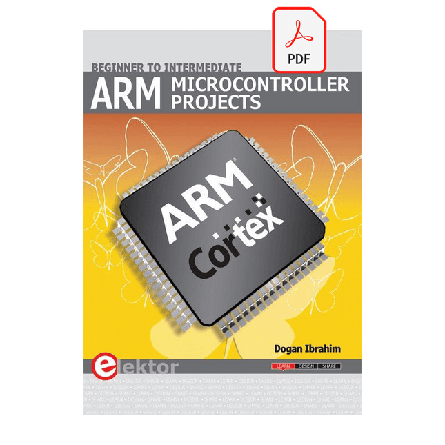
Elektor Digital ARM Microcontroller Projects (E-book)
It is becoming important for microcontroller users to quickly learn and adapt to new technologies and architecture used in high performance 32-bit microcontrollers. Many manufacturers now offer 32-bit microcontrollers as general purpose processors in embedded applications. ARM provide 32 and 64-bit processors mainly for embedded applications. These days, the majority of mobile devices including mobile phones, tablets, and GPS receivers are based on ARM technology. The low cost, low power consumption, and high performance of ARM processors makes them ideal for use in complex communication and mixed signal applications. This book makes use of the ARM Cortex-M family of processors in easy-to-follow, practical projects. It gives a detailed introduction to the architecture of the Cortex-M family. Examples of popular hardware and software development kits are described. The architecture of the highly popular ARM Cortex-M processor STM32F107VCT6 is described at a high level, taking into consideration its clock mechanisms, general input/output ports, interrupt sources, ADC and DAC converters, timer facilities, and more. The information provided here should act as a basis for most readers to start using and programming the STM32F107VCT6 microcontroller together with a development kit. Furthermore, the use of the mikroC Pro for ARM integrated development environment (IDE) has been described in detail. This IDE includes everything required to create a project; namely an editor, compiler, simulator, debugger, and device programmer. Although the book is based on the STM32F107VCT6 microcontroller, readers should not find it difficult to follow the projects using other ARM processor family members.
€ 34,95
Mitglieder: € 31,46
-
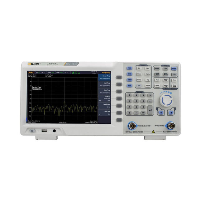
OWON OWON XSA815-TG Spektrum-Analyzer (9 kHz - 1,5 GHz)
Der OWON XSA815-TG 9 kHz-1,5 GHz ist ein kostengünstiger Spektrumanalysator mit Tracking-Generator und einer Frequenzauflösung von 1 Hz.FeaturesFrequenzbereich von 9 kHz bis 1,500009 GHz9-Zoll-Display9 kHz bis 1 MHz -95 dBm Angezeigter durchschnittlicher Geräuschpegel, 1 MHz bis 500 MHz 140 dBm (typisch), Phasenrauschen-10 kHz 100 kHz 1 MHz Auflösungsbandbreite (-3 dB): 1 Hz bis 1 MHz, in der Reihenfolge 1-3-5-10Tracking-Generator-Kit: 100 kHz bis 1,500009 GHzTechnische DatenFrequenzbereich9 kHz bis 500.009 MHzFrequenzauslösung1 HzFrequenzspanne9 kHz bis 1.500009 GHzSpan Range0 Hz, 100 Hz to max frequency of instrumentSpan Uncertainty± span / (sweep points-1)SSB Phase Noise (20°C to 30°C, fc=1 GHz) Carrier Offset10 kHz Resolution Bandwidth (-3 dB)1 Hz to 1 MHz, in 1-3-5-10 sequenceRBW AccuracyResolution Filter Shape Factor (60 dB: 3 dB)Video Bandwidth (-3 dB)10 Hz to 1 MHz, in 1-3-5-10 sequenceAmplitude measurement rangeDANL to +10 dBm, 100 kHz to 10 MHz, Preamp Off DANL to +20 dBm, 10 MHz to 1.5 GHz, Preamp OffReference Level-80 dBm to +30 dBm, 0.01dB by stepPreamp20 dB, nominal, 100 kHz to 1.5 GHzInput Attenuator0 to 40 dB, 1 dB by step Display Average Noise Level Input attenuation = 0 dB, RBW = VBW = 100 Hz, sample detector, trace average ≥ 50, 20°C to 30°C, input impedance = 50 Ω)Preamp Off 9 kHz to 1 MHz-95 dBm (Typical), Preamp Off 1 MHz to 500 MHz-140 dBm (Typical), Preamp On 100 kHz to 1 MHz-135 dBm (Typical), Preamp On 1 MHz to 500 MHz-160 dBm (Typical),Tracking Generator (optional) Frequency Range100 kHz to 1.500009 GHzOutput power level range-40 dBm to 0 dBmOutput level resolution 1 dB Output flatnessRelative to 50 MHz | ±3 dBTracking generator spuriousHarmonic spurious -30 dBc (Tracking generator output power -10 dBm) Non-harmonic spurious -40 dBc (Tracking generator output power -10 dBm)Tracking generator to input terminal isolation-60 dB (Tracking generator output power 0 dBm)Tracking generator to input terminal isolation-60 dB (Tracking generator output power 0 dBm)Tracking generator to input terminal isolation-60 dB (Tracking generator output power 0 dBm)Abmessungen375 x 185 x 120 mmGewicht3,7 kgLieferumfang1x XSA815-TG1x 220 V AC-Netzkabel1x USB-Kabel1x SchnellstartanleitungDownloadsQuick GuideSpecifications
€ 892,50
-

Sensepeek Sensepeek 4012 PCBite Kit inkl. 2x SP10 Sonde für DMM
PCBite ist die Komplettlösung für den Umgang mit Ihrer Leiterplatte während der Entwicklungsphase. Starke Magnete zusammen mit einer rostfreien Grundplatte machen das System flexibel, mobil und benutzerfreundlich. Der Halter kann leicht neu positioniert werden, um Leiterplatten unterschiedlicher Form und Größe zu handhaben. Die Sonden sind stabil und dennoch flexibel und eignen sich für sofortige Messungen oder den völlig freihändigen Betrieb zusammen mit Ihrem Multimeter oder Ihrem bevorzugten Werkzeug. Inbegriffen 4x PCBite-Halter 2x Bananen-zu-DuPont-Testkabel rot/schwarz 2x SP10-Sonde mit rot/schwarzem Sondenkopf und Prüfnadeln mit Stiftspitze 2x zusätzliche Testnadel mit Kronenspitze 1x Satz gelbe Isolierscheiben 1x große Grundplatte (A4) 1x Mikrofasertuch Downloads Benutzerhandbuch
€ 103,22
-

Seeed Studio Seeed Studio RF Explorer WSUB1G+ Slim Spektrum-Analyzer
The Seeed Studio RF Explorer WSUB1G+ is a powerful, high-performance digital spectrum analyzer covering frequencies from 50 kHz to 1 GHz. The Slim model features a robust design, a more conveniently positioned USB connector on the side, and a larger internal battery capacity. Features Internal LNA amplifier and selectable attenuator Low frequency support from 50 KHz covering LF, MF, HF, VHF and UHF up to 960 Mhz New HELP and SET buttons to improve user interface and configuration selection with 2-clicks Wide band coverage to all popular sub-1 Ghz bands, including FM, TV and DTV, ISM, RFID, GSM, etc. Ideal choice for HAM bands from 160 m to 33 cm Pocket size and light weight Solid metal case Spectrum Analyzer mode with Peak Max and Hold, Normal, Overwrite and Averaging modes High capacity internal Lithium battery for 20hs+ of continuous run, rechargeable by USB Multi-platform Windows/Linux/MacOS Open Source software and API libraries Can be extended with internal Expansion Modules for additional band and functionality Technische Daten Frequency band: 0.05 MHz – 960 MHz Frequency span: 0.1 MHz – 960 MHz Internal selectable LNA 25 dB gain Internal selectable Attenuator 30 dB Graphics LCD 128 x 64 pixels, great visibility outdoors Support included for Windows, Linux and MacOS X Backlight for great visibility indoor Internal Lithium Ion 1800 mA/h rechargeable battery Standard SMA 50 Ω connector Wideband 144/433 MHz dual band telescopic antenna included UHF 400-900 MHz rubber duck articulated antenna included Amplitude resolution: 0.5 dBm Dynamic range: -125 dBm to 10 dBm Absolute Max input power: +30 dBm Average noise level (typical LNA): -125 dBm Frequency stability and accuracy (typical): ±10 ppm Amplitude stability and accuracy (typical): ±2 dBm Frequency resolution: 1 kHz Resolution bandwidth (RBW): Automatic 2.6 kHz to 600 kHz Lieferumfang 1x Seeed Studio RF Explorer WSUB1G+ Slim Spectrum Analyzer 1x Mini USB cable 1x Dual band 144/430 MHz Telescopic antenna 1x UHF 400-900 Mhz antenna 1x EVA case
€ 201,11
-

Elektor Digital Elektor Mei/Juni 2020 (PDF)
Open-netwerk weerstation mk2deel 1: inleiding en hardware-elementen AI voor beginners (1)objectherkenning met het Maixduino-board Universele triac-stuurmodule met ATmegaschakelen en dimmen van verschillende belastingen Hoe... iets van GitHub downloadenGitHub Voor Dummies My IoT-Button: de knop voor het netdeel 2: prototyping met board en cloud TMS0280 spraaksynthesizervreemde onderdelen Interactiefcorrecties & updates | vragen & antwoorden BASIC voor ESP32/ESP8266 (2)zandloper met ESP8266 en Annex WiFi RDS Developer’s Zonetips & trucs, vakkunstigheden en andere nuttige informatie BalBot: een zelfbalancerende robotmoderne versnellingssensoren vergemakkelijken de bouw Alle begin......hoeft niet zo moeilijk te zijn Wie het kleine niet eertuit de ideeënbus van Elektor Verzendbox met manipulatie-indicatiegegevens veilig met de post verzenden Nieuwe Nauwkeurige Nixie-klok: verbeteringentechnisch nieuwsbulletin voor nieuwe en bestaande enthousiaste gebruikers Multitasking met de ESP32 (3)software-timers Met de vos in het IoT (4)inrichten van het dashboard Start-up update: het Elektor Investment Program Review: Elektronische USB-belasting Joy-IT HD35test de belastbaarheid van USB-poorten CAN-bus + Arduino houden zonnepanelen in de gatenlokaliseer panelen in grote arrays die onderhoud nodig hebben Analoge elektronica ontwerpencase-study #1 – deel 3: optimalisatie van de responsie van de voorversterker en compromissen Sound Blinkdraagbare zelfbouwspeaker met LED-lichtshow USB-stroombewakingintelligente bescherming voor USB-poorten Oost West Lab Besteen blik in het allerheiligste, waar onbevoegden geen toegang hebben... Review: Labvoeding PeakTech 6080 Aveel voeding voor weinig geld Een grote uitdagingveilige producten in het IoT-tijdperk Elektor 1,2-GHz-universeelteller (1992/93)voorbij de magische 1GHz-grens Hexadoku
€ 9,95
-

Rigol Rigol DG2052 Funktions-/Arbiträrwellenformgenerator (50 MHz)
Highlights Ausgangsfrequenz (Sinus): 50 MHz Ausgangsfrequenz (Rechteck): 15 MHz Kanäle: 2 Länge der beliebigen Wellenform: 16 Mpts Features Einzigartige SiFi II-Technologie (Signal Fidelity II): Generierung beliebiger Wellenformen Punkt für Punkt; Wiederherstellung des Signals ohne Verzerrung; genaue und anpassbare Abtastrate; Jitter aller Ausgangswellenformen (einschließlich Sinus, Puls usw.) nur 200 ps 16 Mpts Speichertiefe pro Kanal für beliebige Wellenformen Standardmäßiger Dual-Channel mit gleicher Leistung, entspricht zwei unabhängigen Signalquellen Hohe Frequenzstabilität: ±1 ppm; geringes Phasenrauschen: -105 dBc/Hz Eingebauter Harmonischengenerator höherer Ordnung (maximal Harmonische 8. Ordnung) Eingebauter Frequenzzähler mit 7 Ziffern/s und 240 MHz Bandbreite und vollem Funktionsumfang Bis zu 160 integrierte beliebige Wellenformen, die die gängigen Signale in technischen Anwendungen, der medizinischen Elektronik, der Autoelektronik, der mathematischen Verarbeitung und vielen anderen Bereichen abdecken Abtastrate bis zu 250 MSa/s, vertikale Auflösung 16 Bit Funktion zum Bearbeiten beliebiger Wellenformsequenzen verfügbar; beliebige Wellenformen können auch über die PC-Software generiert werden Verschiedene analoge und digitale Modulationsfunktionen: AM, FM, PM, ASK, FSK, PSK und PWM. Standardmäßige Wellenform-Kombinationsfunktion, die die Ausgabe bestimmter Wellenformen in Kombination mit den Basiswellenformen ermöglicht Standardmäßige Kanalverfolgungsfunktion. Wenn aktiviert, werden alle Parameter beider Kanäle basierend auf den Benutzerkonfigurationen aktualisiert. Standardschnittstelle: USB Host&Device und LAN (LXI Core 2011 Device); USB-GPIB-Funktion wird unterstützt 4,3-Zoll-TFT Lieferumfang 1x Rigol DG2052 Funktions-/Arbiträrwellenformgenerator 1x Netzkabel 1x USB-Kabel
€ 652,19
Bestpreis
-

Elektor Digital Elektor 07-08/2023 (PDF)
Diese Ausgabe steht allen GOLD- und GREEN-Mitgliedern auf der ElektorMagazine-Website zum Download bereit! Sind Sie noch kein Mitglied? Hier klicken! Drehscheibentelefon als Fernbedienung Licht einschalten, wählen Sie die 1, Kaffeemaschine einschalten, wählen Sie die 2 GPS-gestützte Geschwindigkeitsüberwachung Nie mehr Rasen, nie mehr Knöllchen! RGB-Stroboskop mit Arduino Farbenfrohe Anwendung eines nützlichen Werkzeugs Drahtloser Notruf-Taster Erhöhte Sicherheit mit LoRa Aller Anfang... …muss nicht schwer sein: Folgen Sie dem Emitter! Beliebige und unabhängige Hysteresestufen für Komparatoren mit Simulationen, Tabellenkalkulationen und etwas Algebra ESP32-basierter Impedanz-Analysator Einfach, kompakte Bauteile und preiswert! Das besondere Projekt Ermutigung zum Heimwerken Mikrocontroller-Praxiskurs für Arduino-Einsteiger mit Trainingsboard All-in-One-Trainingshardware für den Mikrocontroller-Kurs Aus dem Leben gegriffen Moderner Luddismus Sensor 1x1: Temperatur-Sensor DS18B20 Anschluss am 1-Draht-Bus Rettet Matter das Smart Home? Neue Standards zur Vereinfachung der Hausautomatisierung Eine Frage der Zusammenarbeit Entwickeln mit dem Board Thing Plus Matter und dem Simplicity Studio Infografik: IoT und Sensoren Matter, ExpressLink, Rainmaker – Worum geht es eigentlich? Interview mit Amey Inamdar von Espressif Development-Kits für IoT- und IIoT-Anwendungen Über die Auswahl von Mikrocontroller-Entwicklungsboards Kondensatoren verhalten sich nicht immer kapazitiv Eine NTP-Uhr mit CircuitPython Warum Sie diese Programmiersprache verwenden sollten Bauen Sie ein cooles IoT-Display Mit dem Phambili Newt Der Doppler-Bewegungssensor HB100 Theorie und Praxis eines ungewöhnlichen Sensors Eine Anleitung zur Bare-Metal-Programmierung Teil 1: STM32 und andere Controller Siglent-Multimeter SDM3045X Mikroprozessoren für virtuelle Systeme Bemerkenswerte Bauteile Mikrocontroller-Dokumentation verstehen Teil 3: Blockdiagramme und mehr LoRa-Wetterstation mit niedriger Stromaufnahme Bauen Sie Ihre entfernte Wetterstation selbst! Transverter für das 70-cm-Band Klima ruft Ingenieure Bewegen Sie sich schnell und reparieren Sie die Dinge Hexadoku
€ 11,90
-

Elektor Digital Elektor September/October 2022 (PDF)
Elektor GREEN and GOLD members can download their digital edition here. Not a member yet? Click here. electronica fast forward 2022 Start- & Scale-Up AwardsPreparations Speeding Up! Bluetooth Low Energy with ESP32-C3 and ESP32You Don’t Always Need to Choose Wi-Fi! Bluetooth Low Energy SnifferHacking a makerdiary nRF52840 MDK USB Dongle Magic RGB LED CubeHardware Design Around an RP2040 Auto On/Off for Solder Paste Compressor Elektor Video ContentLivestreams, Webinars, and Courses for Engineers and Pro Makers Bicycle ElectrificationHands-On with an E-Bike Retrofit Kit Starting Out in ElectronicsMultiplying Voltages From Life’s ExperienceSidelines Teensy 4.0Why Is This Board So Fast? Audio Power Amplifier Simulation with TINAThe Try-Before-You-Build Approach Develop and Operate Your LoRaWAN IoT NodesSample Chapter: Dragino LHT65, LDS01, and LDS02 LoRaWAN Modules Err-lectronicsCorrections, Updates and Readers’ Letters 5G Just for MeGaining Complete Control of 5G Deployments with Private Cellular Networks Infographics 7-8/2022 How Does My Device Learn to Transmit?Applications with Wi-Fi Interfaces Smartphones are the Heart of the IoT Audio Spectrum Analyzer with DekatronsA New Way to Use Vintage Tubes Sending Data to TelegramGet It Done with an ESP32 and a Few Parts A Fliege Notch Filter for Audio MeasurementsMake Better Measurements with a Notch Filter CO2 Meter TeardownIs It Hackable for Your Projects? PUT-ting It All TogetherThe Programmable Unijunction Transistor Explained Round Touchscreen for Raspberry PiHyperPixel 2.1 Round from Pimoroni Remote Sensing with Connection Loss DetectionUsing nRF24L01+ Modules Digital FM Receiver with Arduino and TEA5767Stayed Tuned with an Arduino Nano Changing an OLED Interface from SPI to I²C HomeLab ToursA Hobby Does Not Retire A Decade of Ethics in ElectronicsTessel Renzenbrink Reflects on the Digital Society and More HexadokuThe Original Elektorized Sudoku
€ 7,50
-

Holybro Holybro QAV 250 ARF Drohnen-Kit
Das QAV250-Kit ist der perfekte Einstieg in die Entwicklung auf PX4 oder Ardupilot. Es kombiniert einen Carbonfaser-250-Rennrahmen und wichtige Elektronik mit dem Mini-Autopiloten Pixhawk 6C. Der Bausatz ist einfach zu montieren, Löten ist nicht erforderlich. Technische Daten Micro-Leistungsmodul (PM06 v2) Motoren: 2207 KV1950 Radstand: 250 mm Abmessungen: 198 x 235 x 70 mm Gewicht: 347 g Lieferumfang Carbonfaser-250-Flugzeugzelle mit Hardware Micro-Leistungsmodul (PM06 v2) Motoren: 2207 KV1950 5" Kunststoff-Requisiten Vollständig montiertes Power Management Board mit ESCs (BLHeli S ESC 20A) Akkugurte Hinweis: Der LiPo-Akku ist nicht im Lieferumfang enthalten.
€ 214,95
Bestpreis


