
Suchergebnisse für "joy OR it OR um25c OR usb OR measuring OR device"
-

OWON OWON SDS1104 4-Kanal Oszilloskop (100 MHz)
Das OWON SDS1104 Oszilloskop ist eine praktische Wahl für Ingenieure, Techniker, Studierende und Hobbyelektroniker, die eine präzise Signalanalyse benötigen, ohne in teure High-End-Messgeräte investieren zu müssen. Mit einer Bandbreite von 100 MHz und einer Abtastrate von 1 GSa/s erfasst es Signale im niedrigen bis mittleren Frequenzbereich zuverlässig und eignet sich damit ideal für Elektronikentwicklung, Fehlersuche und den Einsatz in der Ausbildung. Ausgestattet mit einem 7-Zoll-Farb-TFT-Display bietet das SDS1104 eine klare Darstellung von Signalverläufen. Automatische Messfunktionen und FFT-Analyse helfen Anwendern dabei, Frequenz-, Spannungs- und Zeitparameter schnell zu bewerten. Erweiterte mathematische Funktionen, Cursor-Messungen und mehrere Trigger-Modi sorgen für zusätzliche Flexibilität und machen das Oszilloskop zu einem vielseitigen Werkzeug für unterschiedlichste Testszenarien. Technische Daten Bandwidth 100 MHz Sample Rate 1 GS/s Horizontal Scale (s/div) 5ns/div - 1000s/div, step by 1 - 2 - 5 Channel 4 Display 7" color LCD, 800 x 480 pixels Input Coupling DC, AC and GND Vertical Resolution (A/D) Vertical Resolution (A/D) Vertical Sensitivity 5mV/div - 5V/div (at input) Trigger Type Edge, Video Trigger Mode Auto, Normal and Single Waveform Math +, -, x, ÷, invert, FFT Fuse 2A, T class, 250 V Dimension (W x H x D) 301 x 152 x 70 mm Weight 1.1 kg Lieferumfang 1x OWON SDS1104 Oscilloscope 1x Mains power cord 1x CD Rom 1x Quickstart Guide 1x USB Cable 4x Oscilloscope probe 1x Probe Adjust Downloads Datasheet Manual
€ 244,88
-

Elektor Bundles MakePython ESP32 Development Kit (EN)
Learn how to use the ESP32 Microcontroller and MicroPython programming in your future projects! The project book, written by well-known Elektor author Dogan Ibrahim, holds many software- and hardware-based projects especially developed for the MakePython ESP32 Development Kit. The kit comes with several LEDs, sensors, and actuators. The kit will help you acquire the basic knowledge to create IoT projects. The book’s fully evaluated projects feature all the supplied components. Each project includes a block diagram, a circuit diagram, a full program listing, and a complete program description. Included in the kit 1x MakePython ESP32 development board with LCD 1x Ultrasonic ranging module 1x Temperature and humidity sensor 1x Buzzer module 1x DS18B20 module 1x Infrared module 1x Potentiometer 1x WS2812 module 1x Sound sensor 1x Vibration sensor 1x Photosensitive resistance module 1x Pulse sensor 1x Servo motor 1x USB cable 2x Button 2x Breadboard 45x Jumper wire 10x Resistor 330R 10x LED (Red) 10x LED (Green) 1x Project book (206 pages) 46 Projects in the Book LED Projects Blinking LED Flashing SOS Blinking LED – using a timer Alternately flashing LEDs Button control Changing the LED flashing rate using pushbutton interrupts Chasing-LEDs Binary-counting LEDs Christmas lights (random-flashing 8 LEDs) Electronic dice Lucky day of the week Pulsewidth Modulation (PWM) Projects Generate a 1000-Hz PWM waveform with 50% duty cycle LED brightness control Measuring the frequency and duty cycle of a PWM waveform Melody maker Simple electronic organ Servo motor control Servo motor DS18B20 thermometer Analog To Digital Converter (ADC) Projects Voltmeter Plotting the analog input voltage ESP32 internal temperature sensor Ohmmeter Photosensitive resistance module Digital To Analog Converter (DAC) Projects Generating fixed voltages Generating a sawtooth-wave signal Generating a triangular-wave signal Arbitrary periodic waveform Generating a sinewave signal Generating accurate sinewave signal using timer interrupts Using The OLED Display Seconds counter Event counter DS18B20 OLED based digital thermometer ON-OFF temperature controller Measuring the temperature and humidity Ultrasonic distance measurement Height of a person (stadiometer) Heart rate (pulse) measurement Other Sensors Supplied with the Kit Theft alarm Sound-activated light Infrared obstacle avoidance with buzzer WS2812 RGB LED ring Timestamping temperature and humidity readings Network Programming Wi-Fi scanner Remote control from the Internet browser (using a smartphone or PC) – Web Server Storing temperature and humidity data in the Cloud Low-Power Operation Using a timer to wake up the processor
€ 89,95€ 69,95Bestpreis
-

Elektor Publishing Logic Analyzers in Practice
PC USB Logic Analyzers with Arduino, Raspberry Pi, and Co. Step-by-step instructions guide you through the analysis of modern protocols such as I²C, SPI, UART, RS-232, NeoPixel, WS28xx, HD44780 and 1-Wire. With the help of numerous experimental circuits based on the Raspberry Pi Pico, Arduino Uno and the Bus Pirate, you will learn the practical application of popular USB logic analyzers. All the experimental circuits presented in this book have been fully tested and are fully functional. The necessary program listings are included – no special programming or electronics knowledge is required for these circuits. The programming languages used are MicroPython and C along with the development environments Thonny and Arduino IDE. This book uses several models of flexible and widely available USB logic analyzers and shows the strengths and weaknesses of each price range. You will learn about the criteria that matter for your work and be able to find the right device for you. Whether Arduino, Raspberry Pi or Raspberry Pi Pico, the example circuits shown allow you to get started quickly with protocol analysis and can also serve as a basis for your own experiments. After reading this book, you will be familiar with all the important terms and contexts, conduct your own experiments, analyze protocols independently, culminating in a comprehensive knowledge set of digital signals and protocols.
€ 34,95
Mitglieder: € 31,46
-

tinySA tinySA Ultra+ ZS407 Spektrum-Analyzer
The tinySA Ultra+ ZS-407 is a compact, handheld spectrum analyzer and signal generator. Covering 100 kHz to 7.3 GHz in Ultra mode, it lets you visualize and analyze RF signals from HF right through many modern wireless bands – and can even spot signals up to ~12 GHz thanks to harmonic tracking. The intuitive 4-inch resistive touchscreen and rechargeable battery make it great for fieldwork, while features like a built-in signal generator, switchable bandpass filters, step attenuator, USB-PC control and auto-calibration add serious versatility. Features Screen size: 4 inch (480 x 320) Spectrum Analyzer for 0.1-900 MHz or, with Ultra mode enabled up to 7.3 GHz, level calibrated up to 7.3 GHz. Can observe signals up to 12 GHz Signal Generator with sine wave output between 0.1-900 MHz or square wave up to 6.3 GHz or RF test signal output up to 7.3 GHz when not used as Spectrum Analyzer. Switchable resolution bandpass filters from 200 Hz to 850 kHz Built-in 20 dB optional LNA Color display showing max 450 points providing gapless covering up to the full frequency range. MicroSD card slot for storing measurements, settings and screen captures. Technische Daten (Spektrum-Analyzer) Input frequency range from 100 kHz to 900 MHz in normal mode and up to 7.3 GHz with ULTRA mode enabled Input impedance 50 ohm when input attenuation set to 10 dB or more. Selectable manual and automatic input attenuation between 0 dB and 31 dB in 1 dB steps when LNA not active Maximum +/-5V DC input Absolute maximum input level of +6 dBm with 0 dB internal attenuation Absolute maximum short term peak input power of +20 dBm with 30 dB internal attenuation Suggested maximum input power of +0 dBm with internal attenuation in automatic mode For best measurements keep input power below -25 dBm Input Intercept Point of third order modulation products (IIP3) of +15 dBm with 0 dB internal attenuation 1 dB compression point at -1 dBm with 0 dB internal attenuation Power detector resolution of 0.5 dB and linearity versus frequency of ±2 dB below 5.3 GHz, ±5dB between 5.3 GHz and 6 GHz Minimum burst length for correct level measurement at 850 kHz RBW in zero span mode of 50 microseconds Absolute power level accuracy after power level calibration of ±2 dB Built-in optional 20 dB LNA with Noise Figure of 5 dB up to 6 GHz Lowest discernible signal without LNA at 30 MHz using a resolution bandwidth of 30 kHz of -102 dBm Lowest discernible signal with LNA at 30 MHz using a resolution bandwidth of 200 Hz of -145 dBm Frequency accuracy equal to the selected resolution bandwidth Phase noise at 30 MHz of -108 dB/Hz at 100 kHz offset and -115 dB/Hz at 1MHz offset Spur free dynamic range when using a 30 kHz resolution bandwidth of 70 dB Resolution filters with a width of 0.2, 1, 3, 10, 30, 100, 300, 600 and 850 kHz On screen resolution of 51, 101, 145, 290 or 450 measurement points. Scanning speed of over 1000 points/second using largest resolution filters. Automatic optimization of actual scanning points to ensure coverage of the whole scan range regardless of the chosen resolution bandwidth Spur suppression option for assessing if certain signals are internally generated or actually present in the input signal Headphone output for listening to the demodulated audio (AM only). Stereo connector with or without microphone, high impedance is louder, short protected Technische Daten (Signalgenerator) Sine wave output with harmonics below -40 dB of fundamental from 100 kHz to 900 MHz Output level selectable in 1 dB steps between -115 dBm and -19 dBm Above 800 MHz choice of two output modes: Cleanest signal mode: square wave, up to 6 GHz with coarse frequency steps and less accurate output level Highest accuracy mode: reduced harmonics with possibly strong spurs up to 7.3 GHz with frequency resolution equal to below 800 MHz and fine output level steps Level accuracy ±2 dB up to 800 MHz between -72 dBm and -19 dBm, less accuracy below -72 dBm, even less accuracy below -110 dBm Output frequency resolution 57.2 Hz Optional AM or FM modulation frequencies between 50 Hz and 5 kHz (AM) or 1 kHz (FM) or sweep over selectable frequency span AM modulation depth between 10% and 100% FM deviation between 1 kHz and 300 kHz Optional output level sweep over maximum the entire output level range Lieferumfang 1x tinySA Ultra+ ZS407 Spectrum Analyzer 2x SMA connection cables 1x Barrel connector 1x Antenna with SMA connector 1x USB-C cable 1x microSD card (32 GB) Downloads Wiki
€ 192,78
-

Rigol Rigol DSA815-TG Spektrum-Analyzer (9 kHz – 1,5 GHz)
Highlights Frequenz: 1,5 GHz DANL: -155 dBm Phasenrauschen: -80 dBc/Hz RBW: 10 Hz Tracking-Generator Technische Daten Volldigitale ZF-Technologie Frequenzbereich von 9 kHz bis 1,5 GHz Mindest. -161 dBm Angezeigter durchschnittlicher Geräuschpegel (typisch) Mindest. < -98 dBc/Hz bei 10 kHz Offset-Phasenrauschen Pegelmessunsicherheit < 0,8 dB 10 Hz Mindestauflösungsbandbreite Bis zu 1,5 GHz Tracking-Generator Erweiterte Messfunktionen (Opt.) EMI-Filter und Quasi-Peak-Detektor-Kit (Opt.) VSWR-Messkit (Opt.) PC-Software (Opt.) Optionales RF-TX/RX-Trainingskit Optionales HF-Zubehör (Kabel, Adapter, Dämpfungsglied, Brücke...) Vollständige Konnektivität: LAN (LXI), USB-Host und -Gerät, GPIB (Opt.) 8-Zoll-WVGA-Display (800 x 480). Kompakte Größe, leichtes Design Lieferumfang 1x Rigol DSA815-TG Spektrumanalysator 1x Netzkabel 1x USB-Kabel
€ 1.082,95€ 974,66Bestpreis
-

Siglent Siglent SDS1204X-E 4-Kanal Oszilloskop (200 MHz)
Das Siglent SDS1204X-E ist ein leistungsstarkes 200-MHz-Vierkanal-Oszilloskop, das auf der gleichen Plattform wie das sehr beliebte SDS1202X-E basiert, jedoch mehrere wesentliche Verbesserungen aufweist, darunter zwei 1-GSa/s-ADCs und zwei 14-Mpt-Speichermodule. Die Wellenform-Erfassungsraten betragen bis zu 100.000 Wfms/s im Normalmodus und 400.000 Wfms/s im Sequenzmodus. Die SDS1000X-E-Zielfernrohre verfügen über ein großes 7-Zoll-Farbdisplay mit 256 Stufen und Funktionen zur Intensitätsabstufung und Farbtemperatur. Technische Daten Bandbreite 200 MHz Abtastrate (max.) 1 GSa/s Kanäle 2CH+EXT 4CH Speichertiefe (max.) 7 Mpts/CH (kein Interleave-Modus); 14 Mpts/CH (Interleave-Modus) Wellenform-Erfassungsrate (max.) 100.000 Wfms/s (Normalmodus), 400.000 Wfms/s (Sequenzmodus) Triggertypen Flanke, Steigung, Impulsbreite, Fenster, Runt, Intervall, Dropout, Muster, Video Serieller Trigger (Standard) I 2 C, SPI, UART/RS232, CAN, LIN Dekodierungstyp (Standard) I 2 C, SPI, UART/RS232, CAN, LIN 16 digitale Kanäle (nur Vierkanalserie, Option) Maximale Wellenform-Erfassungsrate bis zu 1 GSa/s, Aufzeichnungslänge bis zu 14 Mpts/CH USB-AWG-Modul (nur Vierkanalserie, Option) Ein Kanal, 25 MHz, Abtastrate 125 MHz, Wellenlänge 16 kpts Bode-Diagramm (nur Vierkanalserie) Mindeststartfrequenz 10 Hz, Mindestscanbandbreite 500 Hz, maximale Scan-Bandbreite von 120 MHz (abhängig von Oszilloskop und AWG-Bandbreite), 500 maximale Scanfrequenzpunkte USB-WLAN-Adapter (nur Vierkanalserie, Option) 802.11b/g/b, WPA-PSK, der Adapter muss von Siglent geliefert werden, um eine ordnungsgemäße Funktion zu gewährleisten Downloads Datasheet Manual Programming Guide
€ 781,44
Bestpreis
-

Siglent Siglent SDS822X HD 2-Kanal Oszilloskop (200 MHz)
The Siglent SDS822X HD digital storage oscilloscope is based on 2 GSa/s, 12-bit Analog-Digital Converters and front ends with excellent noise floor performance. With a 200 MHz bandwidth, and a maximum record length of 100 Mpts, and the capability to analyze 2 analog channels alongside 16 digital channels, the SDS822X HD is perfectly suited for mixed signal analysis. Features 12-bit High Resolution 12-bit Analog-Digital Convertors with sample rate up to 2 GSa/s Front ends with 70 μVrms noise floor @ 200 MHz bandwidth 2/4 analog channels, up to 700 MHz bandwidth SPO technology Waveform capture rate up to 120,000 wfm/s (normal mode), and 500,000 wfm/s (sequence mode) Supports 256-level intensity grading and color temperature display modes. Up to 50 Mpts record length Digital trigger system Intelligent trigger: Edge, Slope, Pulse width, Window, Runt, Interval, Dropout, Pattern, Video (HDTV supported), Qualified, Nth edge, Delay, Setup/Hold time. Serial bus triggering and decoder, supports protocols I²C, SPI, UART, CAN, LIN. Segmented acquisition (Sequence) mode, dividing the maximum record length into multiple segments (up to 80,000), according to trigger conditions set by the user, with a very small dead time between segments to capture the qualifying event. History waveform record (History) function, the maximum recorded waveform length is 80,000 frames. Automatic measurements on 50+ parameters, supports statistics with histogram, track, trend, Gating measurement, and measurements on Math, History and Ref. 4 Math traces (2 Mpts FFT, addition, subtraction, multiplication, division, integration, differential, square root, etc.), supports formula editor. Abundant data analysis functions such as Search, Navigate, Counter, Bode plot and Power Analysis High Speed hardware-based Mask Test function, with Mask Editor tool for creating user-defined masks 16 digital channels (optional) 25 MHz waveform generator (optional) 7" TFT-LCD display with 1024 x 600 resolution; Capacitive touch screen supports multi-touch gestures. Interfaces include: USB Hosts, USB Device (USBTMC), LAN (VXI-11/Telnet/Socket), Pass/Fail, Trigger Out Built-in web server supports remote control over the LAN port using a web browser. Supports SCPI remote control commands. Supports external mouse and keyboard. Supports NTP. Technische Daten Analog Channels 2 Bandwidth 200 MHz Vertical resolution 12-bit Sample rate (Max.) One channel mode: 100 Mpts/chTwo channel mode: Mpts/chFour channel mode: 25 Mpts/ch Memory depth (Max.) One channel mode: 50 Mpts/chTwo channel mode: 25 Mpts/ch Waveform capture rate (Max.) Normal mode: 120,000 wfm/sSequence mode: 500,000 wfm/s Trigger type Edge, Slope, Pulse width, Window, Runt, Interval, Dropout, Pattern, Video, Qualified, Nth edge, Delay, Setup/Hold time, Serial Serial trigger and decode (Standard) I²C, SPI, UART, CAN, LIN Measurement 50+ parameters, statistics, histogram, trend, and track supported Math 4 traces 2 Mpts FFT, Filter, +, -, x, ÷, ∫dt, d/dt, √, Identity, Negation, Absolute, Sign, ex, 10x, ln, lg, Interpolation, MaxHold, MinHold, ERES, Average. Supports formula editor Data analysis Search, Navigate, History, Mask Test, Counter, Bode plot, and Power Analysis Digital channel (optional) 16-channel; maximum sample rate up to 1 GSa/s; record length up to 10 Mpts USB AWG module (option) One channel, 25 MHz, sample rate of 125 MHz, wave length of 16 kpts, isolated output I/O 2x USB 2.0 Host, USB 2.0 Device, 10/100 M LAN, Auxiliary output (TRIG OUT, PASS/FAIL), SBUS (Siglent MSO) Probe (Standard) Passive probe PB470 for each channel Display 7 TFT-LCD with capacitive touch screen (1024x600) Lieferumfang 1x Siglent SDS822X Oscilloscope 2x Passive probe (200 MHz) PP520 1x Power cord (EU) 1x USB cable 1x Certificate of calibration 1x Quick start Downloads Datasheet Manual Programming guide
€ 635,25
Bestpreis
-

Sensepeek Sensepeek 6005 enthält 4x SQ10-Sonden inklusive Testkabel.
Die SQ-Serie der handsfree PCBite-Sonden von Sensepeek ist isoliert, wird mit farbcodierten Kabelhaltern geliefert und hat einen niedrigeren Schwerpunkt, was sie im Vergleich zur ursprünglichen SP-Serie der Sonden noch stabiler macht. Alle beliebten Funktionen der berührungslosen Messung, des austauschbaren Feinraster-Federkugelteststifts und des minimalistischen Designs wurden beibehalten, um herkömmliche Sonden in Standardgröße und Handheld-Sonden überflüssig zu machen. Funktionen Alle berührungslosen Sonden von Sensepeek ermöglichen schnelle Messungen oder lange Trigger-Sitzungen. Kein Löten von Drähten zur Verbindung Ihrer Sonde oder komplizierte Werkzeuge zum Einrichten mehr erforderlich. Positionieren Sie einfach die Sonde auf einem beliebigen Prüfpunkt oder Bauteil im Signalpfad und lassen Sie sie los. Spart Zeit und Frustration bei Entwicklung, Verifizierung und Reparaturen. Das minimalistische Design und die federbelastete Testnadel ermöglichen gleichzeitige Messungen an eng beieinander liegenden Komponenten und benachbarten Signalen. Sowohl die Länge als auch das Gewicht der SQ-Sonden sind perfekt ausbalanciert und können mit den PCBite-PCB-Haltern und der Basisplatte verwendet werden, was für die berührungslose Funktion unerlässlich ist. Der Sondenhalter ist mit einem starken Magneten in der Basis ausgestattet, wie bei allen PCBite-Sonden und -Haltern, was das Platzieren und Neupositionieren der Sonde erleichtert. Die SQ-Serie von Sonden kann auch ohne den Sondenhalter von Hand verwendet werden, da sie über einen isolierten Griff verfügen, ihr volles Potenzial wird jedoch bei der berührungslosen Messung genutzt. Im Lieferumfang enthalten 4x SQ10-Sonden und Pin-Testnadeln (schwarz) 2x Banane-zu-Dupont-Testdrähte (rot/schwarz) 5x Dupont-zu-Dupont-Testdrähte 1x Satz Kabelhalter (4 Farben) 4x zusätzliche Testnadeln Downloads Benutzerhandbuch
€ 105,91
-

Elektor Labs Elektor Rauscharmes Labornetzteil
Das rauscharme Labornetzteil von Elektor ist ein vollständig analoges, einstellbares, symmetrisches Gerät mittlerer Leistung, das ohne Schalt- oder digitale Komponenten auskommt. Es bietet eine Ausgangsspannung, die zwischen 0 V und ±22 V einstellbar ist, sowie einen Ausgangsstrom, der von 0 A bis 1 A eingestellt werden kann. Da auf jegliche Art von Schalttechnik verzichtet wird, liefert das Design extrem geringes Rauschen. Zur Anzeige beider Ausgangsspannungen und -ströme werden vier kleine analoge Einbauinstrumente mit Drehspulmesswerk verwendet. Die meisten modernen Labornetzgeräte und AC-Adapter arbeiten mit Schaltnetzteiltechnik. Selbst die besten Ausführungen weisen zwangsläufig hochfrequente Restwelligkeit und andere Schaltartefakte am Ausgang auf, die die Prüfung empfindlicher analoger Schaltungen stören und Messungen kleiner Signale beeinträchtigen können. Um dieses Problem zu vermeiden, setzt dieses Konzept auf ein vollständig analoges Netzgerät. Obwohl es weniger effizient ist als vergleichbare Schaltnetzteile, spielt die geringere Effizienz beim Einsatz auf dem Prüfstand kaum eine Rolle und sorgt für sauberere und zuverlässigere Messergebnisse. Da viele analoge Schaltungen eine symmetrische Versorgung benötigen, liefert dieses Design positive und negative Ausgangsspannungen gleicher Höhe. Eine geringfügige Nachjustierung ist möglich, um eventuelle Ungleichgewichte auszugleichen. Selbstverständlich ist auch eine einstellbare Strombegrenzung integriert. Das Kit enthält die für den Aufbau des Netzteils erforderlichen Komponenten, mit Ausnahme der Transformatoren. Technische Daten Ausgangsspannung 0…+22 V, 0, −22 V Ausgangsstrom 0…+1 A, 0…−1 A Rauschen −85 dBV (bei 0,95 A/20 V, B = 22 kHz) −84 dBV (bei 0,95 A/20 V, B > 500 kHz) Restwelligkeit 50 µVRMS (bei 950 mA/20 V, B = 22 kHz, hauptsächlich 100-Hz-Anteil) Lieferumfang 3x Platinen: Regler (PCB-1), Netzfilter (PCB-2) und Transformator (PCB-3) Alle Bauteile mit Ausnahme der Netztransformatoren 4x Drehspulmesswerke Zusätzliche Teile für die Verdrahtung (Drähte, Bananenbuchsen, Kaltgeräte-Netzmodul usw.) Nicht enthalten Die drei Netztransformatoren Ein Gehäuse Stückliste Für die Spannungsregler-Platine (240386-1) Widerstände (250 mW, 1%) R1 = 12 Ω R2, R8, R37, R62 = 1 MΩ R3, R7, R10, R13, R17, R20, R22, R30, R35, R42, R45, R47, R55, R60 = 100 Ω, 600 mW R4, R5 = 4.7 kΩ R6 = 100 kΩ R9, R12, R14, R36, R38, R39, R61, R63, R66, R72, R78, R79 = 10.0 kΩ, 600 mW R11 = 9.76 kΩ, 600 mW R15, R40 = 44.2 kΩ, 600 mW R16, R41, R77 = 1 kΩ R18, R43 = 1.5 kΩ, 1 W, 5% R19, R44 = 470 Ω, 1 W, 5% R21, R46 = 330 Ω, 600 mW R23, R24, R48, R49 = 1.0 Ω, 1 W R25, R50 = 1 kΩ, 1 W, 5% R26, R28, R51, R53 = 1.000 kΩ 0.1%, 15 ppm/C R27, R29, R52, R54 = 10.00 kΩ 0.1%, 15 ppm/C R31, R56 = 1.2 kΩ, 1 W, 5% R32, R57 = 47 kΩ R33, R58 = 270 Ω R34, R59 = 27 kΩ R64, R69 = 12.0 kΩ R65 = 3.0 kΩ, 600 mW R67, R80 = 470 Ω, 600 mW R68, R70 = 6.8 kΩ, 600 mW R71 = 30.0 kΩ,, 600 mW R73, R74, R75, R76 = 10 MΩ P1, P2, P3 = 10 kΩ, 200 mW, 20%, potentiometer, 1 turns, single, lin., panel mount P4, P5 = 500 Ω, 500 mW, 10%, trimmer, 25 turns, 3296Y-1-501LF Bourns P6, P7 = 10 kΩ, 500 mW, 10%, trimmer, 25 turns, 3296Y-1-501LF Bourns Kondensatoren C1 = 100 nF, 50 V, 10%, ceramic X7R, LS 5 mm C2, C3, C6, C7, C30 = 10 µF, 63V, 20%, LS 2.5 mm, 3000hours@105°C C4, C5, C8, C9, C13, C14, C18, C19, C23, C24, C28, C29, C31, C32, C38, C39 = 100 nF, 250 V, 10%, PET, LS 7.5 mm C10, C20 = 47 nF, 100 V, 5%, PET, LS 5 mm C11, C21 = 10 nF, 100 V, 5%, PET, LS 5 mm C12, C22 = 220 µF, 35 V, 20%, 0.024 Ω, LS2.5/3.5 mm, Ir 3.4 A, 2000hours@125°C, polymer C15, C25 = 120 µF, 50 V, 20%, ESR 0.02 Ω, Diam. 10 mm max., LS 5 mm C16, C26 = 15 nF, 100 V, 5%, PET, LS 5 mm C17, C27 = 47 nF, 100 V, 5%, PET, LS 5 mm C33, C34 = 22 µF, 50 V, 20%, LS 2 mm, 10000 hours @ 105°C C35, C36, C44, C45 = 1 µF, 100 V, 10%, LS 5 mm, ceramic X7R C37 = 100 uF, 50 V, 20%. LS 3.5 mm C40, C41, C42, C43, C46, C47, C48, C49 = 1000 µF, 50 V, 20%, LS 5/7.5 mm, Ir 3.32 A, 10000hours@105°C, D 16 mm C50, C51, C52, C53 = 47 nF, 100 V, 10%, ceramic X7R, LS 5 mm Induktivitäten L1, L2 = 4.7 µH, 3.2 A, 0.033 Ω, LS 5 mm, RLB0914-4R7ML Bourns L3 = Commom mode choke, 14.5 mH, 3 A, SSRH24NH-30145 Kemet Halbleiter D1, D2, D3, D4, D5, D9, D10, D11, D15 = BAT85, DO-34 D6, D7, D12, D13 = SR560, DO-201AD D8, D14, D16 = 1N4148, DO-35 D17 = Zenerdiode, 5.6 V, 0.5 W, DO-41 D18, D19 = 1N4004, DO-41 D20, D21 D22, D23 = V30100CI-M3/P, dual common cathode, TO-220 D24 = Zener diode, 30 V, 1 W, DO-41 LED1, LED2 = LED, red, T-1 (3 mm) LED3, LED4 = LED, green, T-1 (3 mm) TVS1, TVS2 = BZW50-33B, R6 T1, T2, T4 = BC337.25, TO-92 T3 = NJW0302G, TO-3P T5, T6, T8 = BC327.25, TO-92 T7 = NJW0281G, TO-3P T9 = BD139, TO-126 (SOT-32) IC1 = LM334Z, TO-92 IC2 = LM4040AIZ-5.0/NOPB, TO-92 (TO-226AA-3) IC3, IC4 = OPA2992IDR, SOIC-8 IC5, IC6 = OPA4992IDR, SOIC-14 IC7 = OPA992IDBVR, SOT-23-5 IC8 = LM339N, DIP-14 IC9 = LM317, TO-220 IC10 = LM337, TO-220 Sonstiges F1, F2 = 5×20 mm fuse, 1.6 A, fast acting HS1, HS2 = Heatsink MC33271 (for T3/T7), 2.7°C/W, PCB mount, height 63.5 mm K1, K4 = 3-way screw terminal block, LS 3.5 mm, max. 1.5 mm² K2, K3 = 3-way screw terminal block, LS 3.5 mm, max. 1 mm² M1, M3 = Moving coil meter, Range 30 V, type 91C4, 45×45 mm M2, M4 = Moving coil meter, Range 1 A, type 91C4, 45×45 mm² RE1 = Relay DPDT,5V, UA2-5NU Verschiedenes 3× 3-way screw terminal block, LS 3.5 mm, max. 1 mm² (for P1, P2, P3) 4× Pin header, 1×2, vertical, pitch 2.54 mm (for LED1, LED2, LED3, LED4) 4× Pin socket, 1×2, vertical. pitch 2.54 mm (for LED1, LED2, LED3, LED4) 2× Heatsink FK222SA220, 20°C/W, PCB mount (for IC9 & IC10) 2× Mica thermal pad for TO-220, 12×18×0.05 mm (for IC9 & IC10) 2× Insulating bushing IB 6, TO-220 (for IC9 & IC10) 2× Ceramic thermal pad, 23×20×2 mm (for T3 & T7) 2× PCB Fuse Holder, for 5×20 mm fuse, 10 A (for F1, F2) 2× Cover for PCB Fuse Holder, transparent (for F1, F2) 2× 2-way screw terminal block, LS 3.5 mm, max. 1 mm² (for M1 & M3) 2× 2-way screw terminal block, LS 3.5 mm, max. 1.5 mm² (for M2 & M4) 8× M3 solder lug, thickness 0.35 mm (for M1…M4) M4 solder lug, thickness 0.35 mm (to connect 4 mm banana connectors) Screened cable, 1 pair, 2×24 AWG/0.22 mm², 1 m (for P1, P2 & P3) IC socket, DIP, 14 contacts (for IC8) M3 washer, plain, steel M3 screw, 16 mm, steel, pan head M3 nut M3 spring washer 50 mm M3 standoff, steel, male-female 12 mm M3 standoff, steel, male-female 10 mm M3 standoff, steel, male-female M3 screw, 8 mm, steel, pan head Für die Netzfilter-Platine (240386-2) Widerstand R1 = 220 kΩ, 1 W, 500 V, 5% Kondensatoren C1, C2 = 470 nF, 305 VAC, Class X2, 11 × 27 mm max., LS 15/22.5 mm C3, C4, C5, C6 = 2.2 nF, 300 VAC, Class Y2, 13 × 4 mm, LS 10 mm, PP Induktivitäten L1, L2 = Common-mode choke, 6.8 mH, 1.7 A, TDK B82732R2172B030 Halbleiter MOV1 = TVS varistor, 300 VAC, S14K300 (230 VAC, B72214S0301K101) and SK14K150 (150 VAC, B72214S0151K101) Sonstiges K1, K2 = 3-way screw terminal block, LS 7.62 mm F1 = Time-delay fuse, 0.5 A (230 VAC) or 1 A (115 VAC) Verschiedenes 1× Fuse holder, 5×20 mm, 10 A, 500 VAC 1× Transparent fuse cover 4× 10 mm M3 standoff, steel, male–female 4× M3 screw, 8 mm, steel, pan head 4× M3 nut Für die Transformator-Platine (240386-3) Widerstände R1, R2 = 2.7 kΩ, 600 mW, 1% R3 = 10.0 kΩ, 600 mW, 1% Kondensator C1 = 220 µF, 50 V, 20%, Ø10 mm, LS 5 mm, 4000 h @ 105°C Transformatoren (nicht im Lieferumfang dieses Kits enthalten!) TR1, TR2, TR3 = 2×7 V, 25 VA, PCB-mounted toroid, 70060K Talema Halbleiter D1–D4 = 1N4148, DO-35 D5, D6 = 1N4004, DO-41 D7 = Zener 5.6 V, 1.3 W, DO-41 LED1 = LED, red, T-1 (3 mm) IC1, IC2 = MOC8021M, CTR ≥ 1000%, DIP-6 Sonstiges F1, F2, F3 = 160 mA time-delay fuse (230 VAC) or 315 mA time-delay fuse (115 VAC) K1 = 2-way screw terminal block, LS 7.62 mm K2 = 3-way screw terminal block, LS 3.5 mm, max 1.5 mm² K3, K4 = 3-way screw terminal block, LS 3.5 mm, max 1 mm² RE1, RE2 = Relay DPDT, 5 A/250 VAC / 24 VDC Verschiedenes 1× Pin header 1×2, pitch 2.54 mm + matching socket for LED1 3× Fuse holder 5 × 20 mm, 10 A, 500 VAC + transparent cover 3× M4 screw, 8 mm, pan head + washer for TR1-TR3 8× M3 screw, 8 mm, pan head + nut + washer 8× 10 mm M3 standoff, steel, male–female 2× IC socket, DIP-6 for IC1 & IC2 Weitere Bauteile 1 m red insulated wire, stranded, 1.5 mm² 0.5 m blue insulated wire, stranded, 1.5 mm² 0.5 m black insulated wire, stranded, 1.5 mm², 0.5 m 2 m red insulated wire, stranded, D 0.56 mm (0.25 mm²) 2 m black insulated wire, stranded, D 0.56 mm (0.25 mm²) 0.5 m Multicore Cable, Flexible, 3 Core, 0.75 mm² (24 x 0.2 mm) Red banana socket Black banana socket Blue banana socket Green banana socket IEC Power Entry Module with switch, IEC C14 3 crimp terminals, FASTON, 4.75 x 0.81 mm 3 knobs Links Elektor Labs JumpStarter Page Artikel (Teil 1) Artikel (Teil 2)
€ 299,00€ 249,00Bestpreis
-

FNIRSI FNIRSI DPS150 DC-Netzteil (150 W)
Das FNIRSI DPS150 ist ein leistungsstarkes, einstellbares Gleichstromnetzteil, das über eine USB-C-Eingangsschnittstelle und mehrere Stromversorgungsmodi verfügt und eine präzise Einstellung der Ausgangsspannung (0-30 V) und des Ausgangsstroms (0-5 A) ermöglicht. Es bietet einen effizienten, verbrauchsarmen und stabilen Ausgang und ist mit mehreren Sicherheitsschutzfunktionen ausgestattet, darunter Überspannung, Überstrom, Überlastung, Überhitzung und Verpolung. Es kann flexibel für die serielle Verbindung mehrerer Geräte eingesetzt werden, verfügt über eine umfangreiche und benutzerfreundliche Anzeige und Bedienung sowie ein kompaktes und tragbares Design und erfüllt verschiedene Anwendungsanforderungen. Features 30 V, 5 A, 150 W variabler Gleichstrom mit 0,01 V, 0,001 A Präzision, CC/CV-Modi und <20 mV Welligkeit zum Schutz empfindlicher Elektronik. Unterstützt PC-, QC- und DC-Eingänge mit programmierbaren Ausgängen und 6 voreingestellten Spannungs-/Stromeinstellungen. Kompatibel mit 4 mm-Bananensteckern, U-förmigen Anschlüssen und Kupferdrähten für verschiedene Geräte. 8 Sicherheitsmechanismen, einschließlich Überspannungs-, Strom-, Kurzschluss- und Überhitzungsschutz. 2,8" HD-IPS-Bildschirm mit um 90° umklappbarer, numerischer und Kurvenanzeige für einfache Überwachung. Kleines, platzsparendes Design für den Einsatz in Laboren, Reparaturen und Heimwerkerprojekten. Technische Daten Eingangsspannung 5~32 V DC Eingangsstrom 100 mA-5 A Ausgangsspannung 0-30 V Ausgangsstrom 0~5 A Ausgangsleistung 0-150 W Eingabeweg PD-Schnellladegerät QC-Schnellladegerät Powerbank Gleichstromadapter Betriebsumgebung 0-40°C Regulierung laden 0,49% Volllasteffizienz 96,30% Display 2,8 Zoll (320 x 240) Abmessungen 106 x 76 x 28 mm Gewicht 178 g Lieferumfang 1x DPS150 Netzteil 2x Krokodilklemmendrähte (schwarz und rot) 1x Micro-USB-Kabel 1x Manual Downloads Manual Firmware V0.0.1
€ 58,02
-

Rigol Rigol DG2052 Funktions-/Arbiträrwellenformgenerator (50 MHz)
Highlights Ausgangsfrequenz (Sinus): 50 MHz Ausgangsfrequenz (Rechteck): 15 MHz Kanäle: 2 Länge der beliebigen Wellenform: 16 Mpts Features Einzigartige SiFi II-Technologie (Signal Fidelity II): Generierung beliebiger Wellenformen Punkt für Punkt; Wiederherstellung des Signals ohne Verzerrung; genaue und anpassbare Abtastrate; Jitter aller Ausgangswellenformen (einschließlich Sinus, Puls usw.) nur 200 ps 16 Mpts Speichertiefe pro Kanal für beliebige Wellenformen Standardmäßiger Dual-Channel mit gleicher Leistung, entspricht zwei unabhängigen Signalquellen Hohe Frequenzstabilität: ±1 ppm; geringes Phasenrauschen: -105 dBc/Hz Eingebauter Harmonischengenerator höherer Ordnung (maximal Harmonische 8. Ordnung) Eingebauter Frequenzzähler mit 7 Ziffern/s und 240 MHz Bandbreite und vollem Funktionsumfang Bis zu 160 integrierte beliebige Wellenformen, die die gängigen Signale in technischen Anwendungen, der medizinischen Elektronik, der Autoelektronik, der mathematischen Verarbeitung und vielen anderen Bereichen abdecken Abtastrate bis zu 250 MSa/s, vertikale Auflösung 16 Bit Funktion zum Bearbeiten beliebiger Wellenformsequenzen verfügbar; beliebige Wellenformen können auch über die PC-Software generiert werden Verschiedene analoge und digitale Modulationsfunktionen: AM, FM, PM, ASK, FSK, PSK und PWM. Standardmäßige Wellenform-Kombinationsfunktion, die die Ausgabe bestimmter Wellenformen in Kombination mit den Basiswellenformen ermöglicht Standardmäßige Kanalverfolgungsfunktion. Wenn aktiviert, werden alle Parameter beider Kanäle basierend auf den Benutzerkonfigurationen aktualisiert. Standardschnittstelle: USB Host&Device und LAN (LXI Core 2011 Device); USB-GPIB-Funktion wird unterstützt 4,3-Zoll-TFT Lieferumfang 1x Rigol DG2052 Funktions-/Arbiträrwellenformgenerator 1x Netzkabel 1x USB-Kabel
€ 652,19
Bestpreis
-
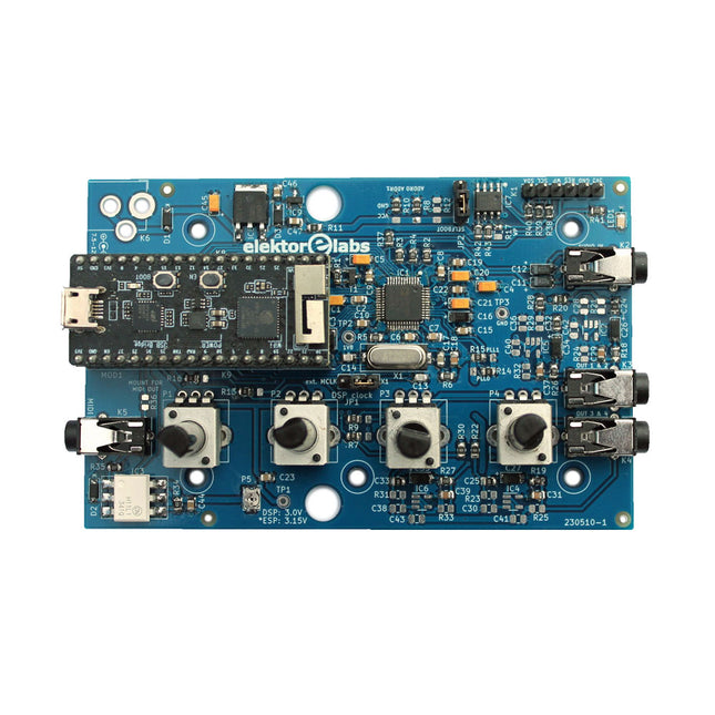
Elektor Labs Elektor Audio DSP FX Processor (Neue Revision)
Der Elektor Audio DSP FX Processor kombiniert einen ESP32-Mikrocontroller und einen ADAU1701 Audio DSP von Analog Devices. Neben einem vom Benutzer programmierbaren DSP-Kern verfügt der ADAU1701 über hochwertige integrierte Analog-Digital- und Digital-Analog-Wandler und verfügt über einen I²S-Port. Dadurch eignet es sich als hochwertiges Audio-Interface für den ESP32. Programme für den ESP32 können mit Arduino, Platform IO, CMake oder durch die Verwendung des Espressif IDF auf andere Weise erstellt werden. Programme für die Audio-DSPs ADAU7101 werden mit dem kostenlosen visuellen Programmiertool SigmaStudio durch Ziehen und Ablegen vordefinierter Algorithmusblöcke auf einer Leinwand erstellt. Anwendungen Bluetooth/Wi-Fi-Audiosink (z. B. Lautsprecher) & Quelle Gitarreneffektpedal (Stomp-Box) Musiksynthesizer Sound-/Funktionsgenerator Programmierbarer Crossover-Filter für Lautsprecher Erweiterter Audioeffektprozessor (Hall, Chorus, Pitch-Shifting usw.) Mit dem Internet verbundenes Audiogerät DSP-Experimentierplattform Drahtloses MIDI MIDI-zu-CV-Konverter und viele mehr... Technische Daten ADAU1701 28-/56-Bit, 50-MIPS digitaler Audioprozessor, der Abtastraten von bis zu 192 kHz unterstützt ESP32 32-Bit-Dual-Core-Mikrocontroller mit Wi-Fi 802.11b/g/n und Bluetooth 4.2 BR/EDR und BLE 2x 24-Bit-Audioeingänge (2 V RMS, 20 kΩ) 4x 24-Bit-Audioausgänge (0,9 V RMS, 600 Ω) 4x Steuerpotentiometer MIDI Ein- und Ausgang I²C-Erweiterungsport Multi-Mode-Betrieb Stromversorgung: 5 V DC USB oder 7,5-12 V DC (Hohlbuchse, mittlerer Pin ist GND) Stromverbrauch (Durchschnitt): 200 mA Lieferumfang 1x ESP32 Audio DSP FX Prozessor Board (montiert) 1x ESP32-PICO-KIT 2x Jumper 2x 18-Pin Header (female) 4x 10 KB Potentiometer Downloads Documentation GitHub
€ 99,95€ 84,95Bestpreis


