
Suchergebnisse für "wireless OR high OR power OR transmission"
-
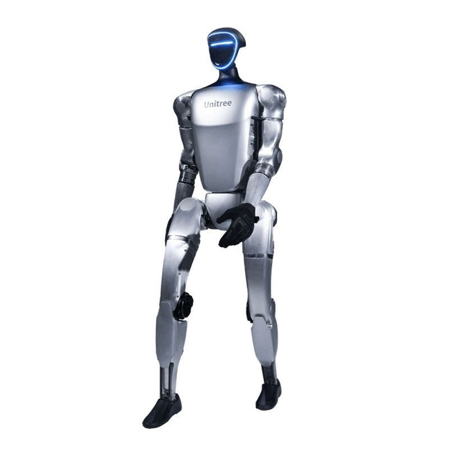
Unitree Unitree G1 Humanoider Roboter
Der Unitree G1 ist ein moderner humanoider Roboter, der durch seine bemerkenswerte Flexibilität und fortschrittliche Technologie beeindruckt. Mit einer außergewöhnlich großen Bandbreite an Gelenkbewegungen und bis zu 43 Gelenkmotoren übertrifft er die Agilität eines typischen Menschen. Seine Robotersysteme werden mit Hilfe von künstlicher Intelligenz durch Imitations- und Verstärkungslernen ständig weiterentwickelt und optimiert. Eine der beeindruckendsten Eigenschaften des G1 ist seine Fähigkeit, sich selbstständig in eine Gehposition zu begeben, sobald er den Boden berührt – ohne externe Hilfe! Er kann sich sofort in Bewegung setzen und beweist damit ein hohes Maß an Unabhängigkeit und Anpassungsfähigkeit. Der G1 ist außerdem mit einer kraftgesteuerten, sehr geschickten Hand ausgestattet, die dank der Kombination aus Kraft- und Positionssteuerung sowohl sensibel als auch präzise arbeitet. Diese Hand ahmt die menschlichen Bewegungen genau nach und ermöglicht eine präzise Handhabung von Objekten. Features Intel RealSense D435 Tiefenkamera Livox MID-360 3D-LiDAR Mikrofonarray (Rausch- und Echounterdrückung) 5 W Stereolautsprecher Extra großer Schnellwechsel-Akku Einzelarm-Freiheitsgrade (Schulter 2 + Ellenbogen 2) Hohlachsverkabelung der gesamten Maschine (keine externen Kabel) Maximales Drehmoment an den Gelenken 120 Nm Einzelbein-Freiheitsgrade (Hüfte 3, Knie 1, Knöchel 2) Bewegungsgeschwindigkeit von 2 m/s Technische Daten Höhe, Breite und Tiefe (stehend) 1320 x 450 x 200 mm Höhe, Breite und Tiefe (gefaltet) 690 x 450 x 300 mm Gewicht (mit Batterie) ca. 35 kg Gesamtfreiheitsgrade (Gemeinsame Freiheit) 23 Einzelbeinige Freiheitsgrade 6 Taillenfreiheitsgrade 1 Einarmige Freiheitsgrade 5 Gelenkabtriebslager Kreuzrollenlager in Industriequalität (hohe Präzision, hohe Belastbarkeit) Gelenkmotor Hochgeschwindigkeits-Innenrotor PMSM (Permanentmagnet-Synchronmotor mit geringer Trägheit – bessere Reaktionsgeschwindigkeit und Wärmeableitung) Maximales Drehmoment des Kniegelenks 90 Nm Maximale Armlast ca. 2 kg Waden- und Oberschenkellänge 0,6 m Armspanne ca. 0,45 m Extra großer Gelenkbewegungsraum • Taillengelenk: Z ±155°• Kniegelenk: 0~165°• Hüftgelenk: P ±154°, R -30~+170°, Y ±158° Vollständige hohle elektrische Leitungsführung Ja Gelenk-Encoder Dual-Encoder Kühlsystem Lokale Luftkühlung Stromversorgung 13-Strang-Lithiumbatterie Grundlegende Rechenleistung 8-Kern-Hochleistungs-CPU Erkennungssensor Tiefenkamera + 3D-LiDAR Mikrofone 4-Mikrofon-Array Lautsprecher 5 W Stereolautsprecher Drahtlos WiFi 6, Bluetooth 5.2 Intelligente Batterie (Schnellverschluss) 9000 mAh Ladegerät 54 V/5 A Manueller Controller Ja Akkulaufzeit ca. 2 Stunden Verbessertes intelligentes OTA Ja
€ 24.999,00
Bestpreis
-

Elektor Labs Elektor Rauscharmes Labornetzteil
Das rauscharme Labornetzteil von Elektor ist ein vollständig analoges, einstellbares, symmetrisches Gerät mittlerer Leistung, das ohne Schalt- oder digitale Komponenten auskommt. Es bietet eine Ausgangsspannung, die zwischen 0 V und ±22 V einstellbar ist, sowie einen Ausgangsstrom, der von 0 A bis 1 A eingestellt werden kann. Da auf jegliche Art von Schalttechnik verzichtet wird, liefert das Design extrem geringes Rauschen. Zur Anzeige beider Ausgangsspannungen und -ströme werden vier kleine analoge Einbauinstrumente mit Drehspulmesswerk verwendet. Die meisten modernen Labornetzgeräte und AC-Adapter arbeiten mit Schaltnetzteiltechnik. Selbst die besten Ausführungen weisen zwangsläufig hochfrequente Restwelligkeit und andere Schaltartefakte am Ausgang auf, die die Prüfung empfindlicher analoger Schaltungen stören und Messungen kleiner Signale beeinträchtigen können. Um dieses Problem zu vermeiden, setzt dieses Konzept auf ein vollständig analoges Netzgerät. Obwohl es weniger effizient ist als vergleichbare Schaltnetzteile, spielt die geringere Effizienz beim Einsatz auf dem Prüfstand kaum eine Rolle und sorgt für sauberere und zuverlässigere Messergebnisse. Da viele analoge Schaltungen eine symmetrische Versorgung benötigen, liefert dieses Design positive und negative Ausgangsspannungen gleicher Höhe. Eine geringfügige Nachjustierung ist möglich, um eventuelle Ungleichgewichte auszugleichen. Selbstverständlich ist auch eine einstellbare Strombegrenzung integriert. Das Kit enthält die für den Aufbau des Netzteils erforderlichen Komponenten, mit Ausnahme der Transformatoren. Technische Daten Ausgangsspannung 0…+22 V, 0, −22 V Ausgangsstrom 0…+1 A, 0…−1 A Rauschen −85 dBV (bei 0,95 A/20 V, B = 22 kHz) −84 dBV (bei 0,95 A/20 V, B > 500 kHz) Restwelligkeit 50 µVRMS (bei 950 mA/20 V, B = 22 kHz, hauptsächlich 100-Hz-Anteil) Lieferumfang 3x Platinen: Regler (PCB-1), Netzfilter (PCB-2) und Transformator (PCB-3) Alle Bauteile mit Ausnahme der Netztransformatoren 4x Drehspulmesswerke Zusätzliche Teile für die Verdrahtung (Drähte, Bananenbuchsen, Kaltgeräte-Netzmodul usw.) Nicht enthalten Die drei Netztransformatoren Ein Gehäuse Stückliste Für die Spannungsregler-Platine (240386-1) Widerstände (250 mW, 1%) R1 = 12 Ω R2, R8, R37, R62 = 1 MΩ R3, R7, R10, R13, R17, R20, R22, R30, R35, R42, R45, R47, R55, R60 = 100 Ω, 600 mW R4, R5 = 4.7 kΩ R6 = 100 kΩ R9, R12, R14, R36, R38, R39, R61, R63, R66, R72, R78, R79 = 10.0 kΩ, 600 mW R11 = 9.76 kΩ, 600 mW R15, R40 = 44.2 kΩ, 600 mW R16, R41, R77 = 1 kΩ R18, R43 = 1.5 kΩ, 1 W, 5% R19, R44 = 470 Ω, 1 W, 5% R21, R46 = 330 Ω, 600 mW R23, R24, R48, R49 = 1.0 Ω, 1 W R25, R50 = 1 kΩ, 1 W, 5% R26, R28, R51, R53 = 1.000 kΩ 0.1%, 15 ppm/C R27, R29, R52, R54 = 10.00 kΩ 0.1%, 15 ppm/C R31, R56 = 1.2 kΩ, 1 W, 5% R32, R57 = 47 kΩ R33, R58 = 270 Ω R34, R59 = 27 kΩ R64, R69 = 12.0 kΩ R65 = 3.0 kΩ, 600 mW R67, R80 = 470 Ω, 600 mW R68, R70 = 6.8 kΩ, 600 mW R71 = 30.0 kΩ,, 600 mW R73, R74, R75, R76 = 10 MΩ P1, P2, P3 = 10 kΩ, 200 mW, 20%, potentiometer, 1 turns, single, lin., panel mount P4, P5 = 500 Ω, 500 mW, 10%, trimmer, 25 turns, 3296Y-1-501LF Bourns P6, P7 = 10 kΩ, 500 mW, 10%, trimmer, 25 turns, 3296Y-1-501LF Bourns Kondensatoren C1 = 100 nF, 50 V, 10%, ceramic X7R, LS 5 mm C2, C3, C6, C7, C30 = 10 µF, 63V, 20%, LS 2.5 mm, 3000hours@105°C C4, C5, C8, C9, C13, C14, C18, C19, C23, C24, C28, C29, C31, C32, C38, C39 = 100 nF, 250 V, 10%, PET, LS 7.5 mm C10, C20 = 47 nF, 100 V, 5%, PET, LS 5 mm C11, C21 = 10 nF, 100 V, 5%, PET, LS 5 mm C12, C22 = 220 µF, 35 V, 20%, 0.024 Ω, LS2.5/3.5 mm, Ir 3.4 A, 2000hours@125°C, polymer C15, C25 = 120 µF, 50 V, 20%, ESR 0.02 Ω, Diam. 10 mm max., LS 5 mm C16, C26 = 15 nF, 100 V, 5%, PET, LS 5 mm C17, C27 = 47 nF, 100 V, 5%, PET, LS 5 mm C33, C34 = 22 µF, 50 V, 20%, LS 2 mm, 10000 hours @ 105°C C35, C36, C44, C45 = 1 µF, 100 V, 10%, LS 5 mm, ceramic X7R C37 = 100 uF, 50 V, 20%. LS 3.5 mm C40, C41, C42, C43, C46, C47, C48, C49 = 1000 µF, 50 V, 20%, LS 5/7.5 mm, Ir 3.32 A, 10000hours@105°C, D 16 mm C50, C51, C52, C53 = 47 nF, 100 V, 10%, ceramic X7R, LS 5 mm Induktivitäten L1, L2 = 4.7 µH, 3.2 A, 0.033 Ω, LS 5 mm, RLB0914-4R7ML Bourns L3 = Commom mode choke, 14.5 mH, 3 A, SSRH24NH-30145 Kemet Halbleiter D1, D2, D3, D4, D5, D9, D10, D11, D15 = BAT85, DO-34 D6, D7, D12, D13 = SR560, DO-201AD D8, D14, D16 = 1N4148, DO-35 D17 = Zenerdiode, 5.6 V, 0.5 W, DO-41 D18, D19 = 1N4004, DO-41 D20, D21 D22, D23 = V30100CI-M3/P, dual common cathode, TO-220 D24 = Zener diode, 30 V, 1 W, DO-41 LED1, LED2 = LED, red, T-1 (3 mm) LED3, LED4 = LED, green, T-1 (3 mm) TVS1, TVS2 = BZW50-33B, R6 T1, T2, T4 = BC337.25, TO-92 T3 = NJW0302G, TO-3P T5, T6, T8 = BC327.25, TO-92 T7 = NJW0281G, TO-3P T9 = BD139, TO-126 (SOT-32) IC1 = LM334Z, TO-92 IC2 = LM4040AIZ-5.0/NOPB, TO-92 (TO-226AA-3) IC3, IC4 = OPA2992IDR, SOIC-8 IC5, IC6 = OPA4992IDR, SOIC-14 IC7 = OPA992IDBVR, SOT-23-5 IC8 = LM339N, DIP-14 IC9 = LM317, TO-220 IC10 = LM337, TO-220 Sonstiges F1, F2 = 5×20 mm fuse, 1.6 A, fast acting HS1, HS2 = Heatsink MC33271 (for T3/T7), 2.7°C/W, PCB mount, height 63.5 mm K1, K4 = 3-way screw terminal block, LS 3.5 mm, max. 1.5 mm² K2, K3 = 3-way screw terminal block, LS 3.5 mm, max. 1 mm² M1, M3 = Moving coil meter, Range 30 V, type 91C4, 45×45 mm M2, M4 = Moving coil meter, Range 1 A, type 91C4, 45×45 mm² RE1 = Relay DPDT,5V, UA2-5NU Verschiedenes 3× 3-way screw terminal block, LS 3.5 mm, max. 1 mm² (for P1, P2, P3) 4× Pin header, 1×2, vertical, pitch 2.54 mm (for LED1, LED2, LED3, LED4) 4× Pin socket, 1×2, vertical. pitch 2.54 mm (for LED1, LED2, LED3, LED4) 2× Heatsink FK222SA220, 20°C/W, PCB mount (for IC9 & IC10) 2× Mica thermal pad for TO-220, 12×18×0.05 mm (for IC9 & IC10) 2× Insulating bushing IB 6, TO-220 (for IC9 & IC10) 2× Ceramic thermal pad, 23×20×2 mm (for T3 & T7) 2× PCB Fuse Holder, for 5×20 mm fuse, 10 A (for F1, F2) 2× Cover for PCB Fuse Holder, transparent (for F1, F2) 2× 2-way screw terminal block, LS 3.5 mm, max. 1 mm² (for M1 & M3) 2× 2-way screw terminal block, LS 3.5 mm, max. 1.5 mm² (for M2 & M4) 8× M3 solder lug, thickness 0.35 mm (for M1…M4) M4 solder lug, thickness 0.35 mm (to connect 4 mm banana connectors) Screened cable, 1 pair, 2×24 AWG/0.22 mm², 1 m (for P1, P2 & P3) IC socket, DIP, 14 contacts (for IC8) M3 washer, plain, steel M3 screw, 16 mm, steel, pan head M3 nut M3 spring washer 50 mm M3 standoff, steel, male-female 12 mm M3 standoff, steel, male-female 10 mm M3 standoff, steel, male-female M3 screw, 8 mm, steel, pan head Für die Netzfilter-Platine (240386-2) Widerstand R1 = 220 kΩ, 1 W, 500 V, 5% Kondensatoren C1, C2 = 470 nF, 305 VAC, Class X2, 11 × 27 mm max., LS 15/22.5 mm C3, C4, C5, C6 = 2.2 nF, 300 VAC, Class Y2, 13 × 4 mm, LS 10 mm, PP Induktivitäten L1, L2 = Common-mode choke, 6.8 mH, 1.7 A, TDK B82732R2172B030 Halbleiter MOV1 = TVS varistor, 300 VAC, S14K300 (230 VAC, B72214S0301K101) and SK14K150 (150 VAC, B72214S0151K101) Sonstiges K1, K2 = 3-way screw terminal block, LS 7.62 mm F1 = Time-delay fuse, 0.5 A (230 VAC) or 1 A (115 VAC) Verschiedenes 1× Fuse holder, 5×20 mm, 10 A, 500 VAC 1× Transparent fuse cover 4× 10 mm M3 standoff, steel, male–female 4× M3 screw, 8 mm, steel, pan head 4× M3 nut Für die Transformator-Platine (240386-3) Widerstände R1, R2 = 2.7 kΩ, 600 mW, 1% R3 = 10.0 kΩ, 600 mW, 1% Kondensator C1 = 220 µF, 50 V, 20%, Ø10 mm, LS 5 mm, 4000 h @ 105°C Transformatoren (nicht im Lieferumfang dieses Kits enthalten!) TR1, TR2, TR3 = 2×7 V, 25 VA, PCB-mounted toroid, 70060K Talema Halbleiter D1–D4 = 1N4148, DO-35 D5, D6 = 1N4004, DO-41 D7 = Zener 5.6 V, 1.3 W, DO-41 LED1 = LED, red, T-1 (3 mm) IC1, IC2 = MOC8021M, CTR ≥ 1000%, DIP-6 Sonstiges F1, F2, F3 = 160 mA time-delay fuse (230 VAC) or 315 mA time-delay fuse (115 VAC) K1 = 2-way screw terminal block, LS 7.62 mm K2 = 3-way screw terminal block, LS 3.5 mm, max 1.5 mm² K3, K4 = 3-way screw terminal block, LS 3.5 mm, max 1 mm² RE1, RE2 = Relay DPDT, 5 A/250 VAC / 24 VDC Verschiedenes 1× Pin header 1×2, pitch 2.54 mm + matching socket for LED1 3× Fuse holder 5 × 20 mm, 10 A, 500 VAC + transparent cover 3× M4 screw, 8 mm, pan head + washer for TR1-TR3 8× M3 screw, 8 mm, pan head + nut + washer 8× 10 mm M3 standoff, steel, male–female 2× IC socket, DIP-6 for IC1 & IC2 Weitere Bauteile 1 m red insulated wire, stranded, 1.5 mm² 0.5 m blue insulated wire, stranded, 1.5 mm² 0.5 m black insulated wire, stranded, 1.5 mm², 0.5 m 2 m red insulated wire, stranded, D 0.56 mm (0.25 mm²) 2 m black insulated wire, stranded, D 0.56 mm (0.25 mm²) 0.5 m Multicore Cable, Flexible, 3 Core, 0.75 mm² (24 x 0.2 mm) Red banana socket Black banana socket Blue banana socket Green banana socket IEC Power Entry Module with switch, IEC C14 3 crimp terminals, FASTON, 4.75 x 0.81 mm 3 knobs Links Elektor Labs JumpStarter Page Artikel (Teil 1) Artikel (Teil 2)
€ 299,00€ 249,00Bestpreis
-

Siglent Siglent SSA3032X Plus Spektrum-Analyzer (9 kHz - 3,2 GHz)
Der Siglent SSA3032X Plus Spektrum-Analyzer ist ein leistungsstarkes und flexibles Werkzeug für die HF-Signal- und Netzwerkanalyse. Mit einem Frequenzbereich von 3,2 GHz bietet der Analysator zuverlässige automatische Messungen und mehrere Betriebsarten: Spektrum-Analyzer als Basis, optionale Funktionen umfassen HF-Leistungsmessung, Vektorsignal-Modulationsanalyse, Reflexionsmessung und EMI-Test. Zu den Anwendungsbereichen gehören die Überwachung/Bewertung von Sendungen, Standortvermessung, S-Parameter-Messung, analoge/digitale Modulationsanalyse, EMI-Vorprüfung, Forschung und Entwicklung, Ausbildung, Produktion und Wartung. Features Frequenzbereich des Spektrum-Analyzer von 9 kHz bis 3,2 GHz –161 dBm/Hz Angezeigter durchschnittlicher Geräuschpegel (typisch) –98 dBc/Hz. @ 10 kHz Offset-Phasenrauschen (1 GHz, typ.) Pegelmessunsicherheit <0,7 dB (typ.) 1 Hz Mindestauflösungsbandbreite (RBW) Vorverstärker (Std.) Tracking Generator (kostenlos inkl.) Analysemodus für analoge und digitale Signalmodulation (opt.) Reflexionsmesskit (opt.) EMI-Filter und Quasi-Peak-Detektor-Kit (opt.) Erweitertes Messkit (opt.) 10,1-Zoll-Multi-Touch-Bildschirm, Maus und Tastatur werden unterstützt Webbrowser-Fernsteuerung auf PCs und mobilen Endgeräten sowie Dateibetrieb Technische Daten SSA3015X Plus SSA3021X Plus SSA3032X Plus SSA3075X Plus Frequenzbereich 9 kHz ~ 1,5 GHz 9 kHz ~ 2,1 GHz 9 kHz ~ 3,2 GHz 9 kHz ~ 7,5 GHz Auflösung Bandbreite 1 Hz ~ 1 MHz 1 Hz ~ 1 MHz 1 Hz ~ 1 MHz 1 Hz ~ 3 MHz Phasenrauschen <–99 dBc/Hz <–98 dBc/Hz <–98 dBc/Hz <–98 dBc/Hz Genauigkeit der Gesamtamplitude <1,2 dB <0,7 dB <0,7 dB <0,7 dB Anzeige des durchschnittlichen Geräuschpegels –156 dBm/Hz –161 dBm/Hz –161 dBm/Hz –165 dBm/Hz Lieferumfang Siglent SSA3032X Plus Spektrum-Analyzer USB-Kabel Netzkabel Kurzanleitung Downloads Datasheet Manual Documentation Firmware
€ 2.951,19
Bestpreis
-

Elektor Digital Elektor 07-08/2026 (PDF) DE
Diese Ausgabe steht allen GOLD- und GREEN-Mitgliedern auf der ElektorMagazine-Website zum Download bereit! Sie sind noch kein Mitglied? Hier klicken! MultiRF-EntwicklungsboardEine Plattform zur Evaluierung drahtloser Protokolle für kurze und lange Reichweiten Elektor wird 65Elektronik im Wandel seit 1961 WLAN-basierte Personenerkennung mit dem ESP32Wenn der Router zum Bewegungsmelder wird Drahtlose WaagenVier kleine Waagen = eine große Waage Walter, das kompakte IoT-ModulESP32-S3-SoC, LTE-M/NB-IoT-5G-Modem und GNSS-Receiver 3- und 4-Draht-RTD-Sensoren konditionierenMit Vollbereichsabgleich und Kabelkompensation Drei in einem: 2-Kanal-Oszilloskop/Generator/MultimeterEin Test des Fnirsi 2D15P electronica Fast Forward 2026 für Start-ups und Industriepartner EcologgingEine modulare IoT-Messstation für Umweltdaten Drahtlos-Anbindung für MedizingeräteImmer am Puls mit Bluetooth LE AudiotronicsBrummunterdrückung Mehr Effizienz in der Landwirtschaft durch KI-Modelle und SensorenSteigerung der landwirtschaftlichen Produktivität OPC UA – ein ÜberblickPlattformunabhängiger Datenaustausch Redox-Meter Instrumentenverstärker für Physik- und Engineering-Experimente Aktive differentielle Audio-FilterFür professionelle Frequenzweichen und mehr Elektor-Community-Tipps zu IoT und Sensoren Telegram-gesteuerter WarmwasserbereiterEine Lösung mit ESP32 und Arduino-Software 2026: Eine KI-OdysseeWas wurde eigentlich aus der Fuzzy-Logik? Projekt 2.0 Alarmsignalinjektor + PowerTools zum Suchen verdeckt verlegter Leitungen
€ 11,90
-

Elektor Digital SDR Hands-on Book (E-book)
The short-wave technique has a very particular appeal: It can easily bridge long distances. By reflecting short-wave signals off the conductive layers of the ionosphere, they can be received in places beyond the horizon and therefore can reach anywhere on earth. Although technology is striving for ever higher frequencies, and radio is usually listened to on FM, DAB+, satellite or the Internet, modern means of transmission require extensive infrastructure and are extremely vulnerable. In the event of a global power outage, there is nothing more important than the short-wave. Amateur radio is not only a hobby, it’s also an emergency radio system! Elektor’s SDR-Shield is a versatile shortwave receiver up to 30 MHz. Using an Arduino and the appropriate software, radio stations, morse signals, SSB stations, and digital signals can be received. In this book, successful author and enthusiastic radio amateur, Burkhard Kainka describes the modern practice of software defined radio using the Elektor SDR Shield. He not only imparts a theoretical background but also explains numerous open source software tools.
€ 29,95
Mitglieder: € 26,96
-

OWON OWON SPS3081 Lüfterloses DC-Netzteil (120 W)
Das lüfterlose programmierbare DC-Netzteil OWON SPS3081 (120 W) bietet extrem leise, hochpräzise Leistung mit einer Genauigkeit von 10 mV/1 mA und fortschrittlicher Wärmeableitung für langfristige Zuverlässigkeit. Mit umfassendem Schutz, einer USB-Schnittstelle mit SCPI-Unterstützung für die Fernbedienung und einem 2,8-Zoll-TFT-LCD-Bildschirm ist es die perfekte Wahl für Labore, Elektroniktests und Forschung. Features Lüfterloses Design: Extrem leiser Betrieb, reduziert Vibrationsgeräusche und minimiert die potenziellen Ausfallrisiken, die mit herkömmlichen Kühlventilatoren verbunden sind. Hervorragendes Wärmeableitungsdesign: Gewährleistet einen kontrollierten Temperaturanstieg, ermöglicht einen langfristigen Betrieb unter Volllastbedingungen und verlängert die Lebensdauer der internen Komponenten. Leichtes und ultradünnes Design. Ausgabegenauigkeit bis zu 10 mV/1 mA Unterstützt die Bearbeitung und Ausgabe von Listenwellenformen mit vier Speicherverknüpfungsparametern für schnellen und bequemen Zugriff. Zu den integrierten Schutzfunktionen gehören Überspannungs-, Überstrom-, Übertemperatur- und Eingangsunterspannungsschutz für mehr Sicherheit. Eingebauter Entladekreis verhindert Restrisiken durch Hochspannung, wenn der Strom ausgeschaltet ist. USB-Kommunikationsschnittstelle mit SCPI-Protokollunterstützung, die PC-Programmierung und Fernsteuerung für eine vereinfachte Benutzerverwaltung ermöglicht. 2,8-Zoll-TFT-LCD-Bildschirm Technische Daten Modell SPS6051 SPS3081 Nennleistung (0°C-40°C) Spannung 0-61 V 0-31 V Strom 0-5,1 A 0-8,1 A Leistung 150 W 120 W Lastregulierung Spannung ≤30 mV Strom ≤20 mA Leistungsregulierung Spannung ≤30 mV Strom ≤20 mA Auflösung festlegen Spannung 10 mV Strom 1 mA Readback-Auflösung Spannung 10 mV Strom 1 mA Einstellgenauigkeit (25°C ±5°C) Spannung ≤0,05% ±20 mV ≤0,1% ±20 mV Strom ≤0,05% ±20 mA ≤0,2% ±20 mA Readback-Genauigkeit (25°C ±5°C) Strom ≤0,05% ±20 mV ≤0,1% ±20 mV Spannung ≤0,05% ±20 mV ≤0,2% ±20 mA Welligkeit/Rauschen Spannung ≤30 mVp-p ≤30 mVp-p Spannung ≤4 mVrms ≤5 mVrms Strom ≤10 mAP-p ≤30 mAP-p Ausgangstemperaturkoeffizient (0°C-40°C) Spannung 100 ppm/°C Strom 200 ppm/°C Readback-Temperaturkoeffizient Spannung 100 ppm/°C Strom 200 ppm/°C Reaktionszeit (50-100% Nennlast) ≤1,0 ms Speicher 4 Datengruppen Betriebsstemperatur 0-40°C Display 2,8" Farb-LCD-Display Schnittstelle USB Abmessungen (B x H x T) 82 x 142 x 226 mm Gewicht 1,8 kg Lieferumfang 1x OWON SPS3081 Netzteil 2x Messleitungen 1x Netzkabel 1x Manual Downloads Datasheet User Manual (German) Programming Manual PC Software
€ 135,66
-

Andonstar Andonstar AD409 Max-ES 10,1" HDMI Digital-Mikroskop (inkl. Endoskop)
Der Andonstar AD409 Max-ES verfügt über eine hochwertige Metalllinse und ein einzigartiges UV-Filterdesign. Er besteht aus erstklassigen Materialien in Industriequalität und bietet unübertroffene Präzision und Haltbarkeit und sorgt so für ein zuverlässiges Produkterlebnis. Der vor der Metalllinse positionierte UV-Filter blockiert Löthitze, Rauch und Staub, schützt die Linse und macht sie perfekt für Löt- und Wartungsprofis. Der AD409 Max-ES verfügt über eine übergroße Max-Station (46 x 37 x 47,5 cm) und ein fortschrittliches Werkzeugset, wodurch die Lötstationsfläche um 370% erweitert wird. Dieses Upgrade erfüllt die Anforderungen professioneller Lötaufgaben und bietet ausreichend Arbeitsfläche für größere Projekte. Der benutzerfreundliche Werkzeughalter hält Werkzeuge griffbereit und sorgt dafür, dass sie immer zugänglich sind. Darüber hinaus vereinfachen die Löthilfshände mit drehbaren Klemmen Löt- und Reparaturarbeiten und steigern so die Effizienz und den Komfort. Das Endoskop bietet eine 360°-Rundumsicht. Dies ermöglicht eine klare Beobachtung der Komponenten von allen Seiten und im Rohrinneren, wodurch tote Winkel vermieden und gründliche Inspektionen gewährleistet werden. Features Hochwertige Metalllinse und einzigartiges UV-Filterdesign Neue Max-Station Benutzerfreundlicher Werkzeughalter und helfende Hände beim Löten Mikroskop mit Endoskop-Rundumblick 360° Professionelles HDMI-Digitalmikroskop unterstützt mehrere Ausgabemethoden In 8 Stufen einstellbare LEDs Praktische kabellose Fernbedienung Technische Daten Bildschirmgröße 10,1 Zoll (1280x800) Bildsensor 4 MP Videoausgang UHD 2880x2160 (24fps)FHD 1920x1080 (60fps/30fps)HD 1280x720 (120fps) Videoformat MP4 Vergrößerung Bis zu 300-fach (27" HDMI-Monitor) Bildauflösung Max. 24 MP (5600x4200) Bildformat JPG Fokusbereich Min. 5 cm Bildrate Max. 120fps Videoschnittstelle HDMI Speichermedium microSD-Karte (bis zu 64 GB) PC-Unterstützung Windows, PC-Software mit Messung Unterstützung von Mobiltelefonen, Tablet-Terminals Unterstützung von WiFi-Verbindung und Messung Stromversorgung 5 V DC Beleuchtung 2 LEDs mit Standfuß Endoskop Ja Abmessungen 46 x 37 x 47,5 cm Lieferumfang 1x Andonstar AD409 Max-ES Digital-Mikroskop 1x Endoskop 1x Metallstativ mit 2 LEDs 1x UV-Filter (bereits im Objektiv montiert) 1x Lötmatte 1x Träger 1x Säule 1x Werkzeughalter 1x Helfende Hand beim Löten 1x Netzteil 1x Stromkabel 1x HDMI-Kabel 1x USB-Kabel 1x IR-Fernbedienung 1x Manual Downloads Manual Software
€ 399,00€ 339,00Bestpreis
-

Elektor Digital Elektor September/October 2023 (PDF)
Elektor GREEN and GOLD members can download their digital edition here. Not a member yet? Click here. Raspberry Pi Pico as Spectrum AnalyzerFFTs on a Low-Cost Hardware Basis ±40-V Linear Voltage RegulatorAn Alternative Power Supply for the Fortissimo-100 Power Amplifier… and Others! MCU Wireless Communication Made FlexibleEEPROM Opens Networking Prospects for Wireless MCUs €5,000 up for grabs!Join the STM32 Wireless Innovation Design Contest 2023: An AI OdysseyGetting Started with ChatGPT’s Code Interpreter LoRa, a Swiss Army Knife (1)The LoRa Protocol and Its Advantages Adjustable Current Sink with Integrated Clock GeneratorTest Power Supplies, Voltage Converters and Batteries Two New Arduino UNO R4 Boards: Minima and WiFi Logarithmic PotentiometersThey’re Exponential! Motor Driver Breakout BoardA BoB for a 5 A DC Motor Driver with a 3×3 mm Size From Life’s ExperienceHazardous Electronics Is Cellular the Lowest-Power Option for IoT?LTE-M and NB-IoT Energy Requirements in LPWAN Deployments Wireless Communication in IoT Systems – Using Arduino MKR ModulesThe Right Board for Wi-Fi, LoRa, and Many More Standards AC Losses in Magnetic ComponentsAvoid Hot Inductors! Measurement for Optimal Cloud Deployment Matter Adoption: What does it take to deploy Matter devices? YARD Stick OneA Sub-1 GHz Wireless Test Tool Latching RelaysPeculiar Parts, the Series PIC O’Clock – In Touch with TimeDesigning an SDR Time Signal Receiver Due Diligence DirectiveBusiness as Usual Will Not Do Starting Out in Electronics……Voltage Amplification Infrasound Recorder with the Arduino Pro MiniA Sample Project from Elektor’s “Arduino & Co.” Book Cloud-Based Energy MeterWith ESP32 Module and PZEM-004T Voltage/Current Sensor A Bare-Metal Programming Guide (Part 2)Accurate Timing, the UART, and Debugging Hexadoku
€ 7,50
-
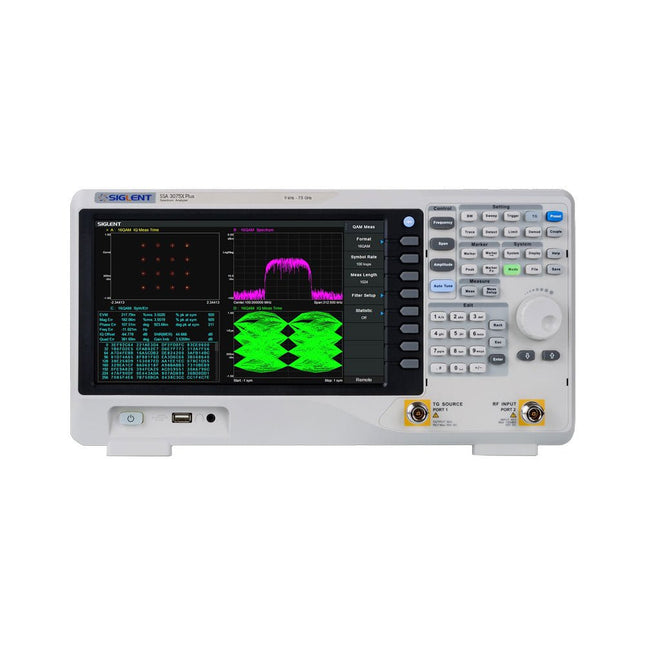
Siglent Siglent SSA3075X Plus Spektrum-Analyzer (9 kHz - 7,5 GHz)
Der Siglent SSA3075X Plus Spektrum-Analyzer ist ein leistungsstarkes und flexibles Werkzeug für die HF-Signal- und Netzwerkanalyse. Mit einem Frequenzbereich von 7,5 GHz bietet der Analysator zuverlässige automatische Messungen und mehrere Betriebsarten: Spektrum-Analyzer als Basis, optionale Funktionen umfassen HF-Leistungsmessung, Vektorsignal-Modulationsanalyse, Reflexionsmessung und EMI-Test. Zu den Anwendungsbereichen gehören die Überwachung/Bewertung von Sendungen, Standortvermessung, S-Parameter-Messung, analoge/digitale Modulationsanalyse, EMI-Vorprüfung, Forschung und Entwicklung, Ausbildung, Produktion und Wartung. Features Frequenzbereich des Spektrum-Analyzer von 9 kHz bis 7,5 GHz –165 dBm/Hz Angezeigter durchschnittlicher Geräuschpegel (typisch) –98 dBc/Hz. @ 10 kHz Offset-Phasenrauschen (1 GHz, typ.) Pegelmessunsicherheit <0,7 dB (typ.) 1 Hz Mindestauflösungsbandbreite (RBW) Vorverstärker (Std.) Tracking Generator (kostenlos inkl.) Analysemodus für analoge und digitale Signalmodulation (opt.) Reflexionsmesskit (opt.) EMI-Filter und Quasi-Peak-Detektor-Kit (opt.) Erweitertes Messkit (opt.) 10,1-Zoll-Multi-Touch-Bildschirm, Maus und Tastatur werden unterstützt Webbrowser-Fernsteuerung auf PCs und mobilen Endgeräten sowie Dateibetrieb Technische Daten SSA3015X Plus SSA3021X Plus SSA3032X Plus SSA3075X Plus Frequenzbereich 9 kHz ~ 1,5 GHz 9 kHz ~ 2,1 GHz 9 kHz ~ 3,2 GHz 9 kHz ~ 7,5 GHz Auflösung Bandbreite 1 Hz ~ 1 MHz 1 Hz ~ 1 MHz 1 Hz ~ 1 MHz 1 Hz ~ 3 MHz Phasenrauschen <–99 dBc/Hz <–98 dBc/Hz <–98 dBc/Hz <–98 dBc/Hz Genauigkeit der Gesamtamplitude <1,2 dB <0,7 dB <0,7 dB <0,7 dB Anzeige des durchschnittlichen Geräuschpegels –156 dBm/Hz –161 dBm/Hz –161 dBm/Hz –165 dBm/Hz Lieferumfang Siglent SSA3075X Plus Spektrum-Analyzer USB-Kabel Netzkabel Kurzanleitung Downloads Datasheet Manual Documentation Firmware
€ 7.875,89
Bestpreis
-

Elektor Digital Building Wireless Sensor Networks with OpenThread (E-book)
Developing CoAP applications for Thread networks with Zephyr This book will guide you through the operation of Thread, the setup of a Thread network, and the creation of your own Zephyr-based OpenThread applications to use it. You’ll acquire knowledge on: The capture of network packets on Thread networks using Wireshark and the nRF Sniffer for 802.15.4. Network simulation with the OpenThread Network Simulator. Connecting a Thread network to a non-Thread network using a Thread Border Router. The basics of Thread networking, including device roles and types, as well as the diverse types of unicast and multicast IPv6 addresses used in a Thread network. The mechanisms behind network discovery, DNS queries, NAT64, and multicast addresses. The process of joining a Thread network using network commissioning. CoAP servers and clients and their OpenThread API. Service registration and discovery. Securing CoAP messages with DTLS, using a pre-shared key or X.509 certificates. Investigating and optimizing a Thread device’s power consumption. Once you‘ve set up a Thread network with some devices and tried connecting and disconnecting them, you’ll have gained a good insight into the functionality of a Thread network, including its self-healing capabilities. After you’ve experimented with all code examples in this book, you’ll also have gained useful programming experience using the OpenThread API and CoAP.
€ 32,95
Mitglieder: € 29,66
-

tinySA tinySA Ultra+ ZS407 Spektrum-Analyzer
The tinySA Ultra+ ZS-407 is a compact, handheld spectrum analyzer and signal generator. Covering 100 kHz to 7.3 GHz in Ultra mode, it lets you visualize and analyze RF signals from HF right through many modern wireless bands – and can even spot signals up to ~12 GHz thanks to harmonic tracking. The intuitive 4-inch resistive touchscreen and rechargeable battery make it great for fieldwork, while features like a built-in signal generator, switchable bandpass filters, step attenuator, USB-PC control and auto-calibration add serious versatility. Features Screen size: 4 inch (480 x 320) Spectrum Analyzer for 0.1-900 MHz or, with Ultra mode enabled up to 7.3 GHz, level calibrated up to 7.3 GHz. Can observe signals up to 12 GHz Signal Generator with sine wave output between 0.1-900 MHz or square wave up to 6.3 GHz or RF test signal output up to 7.3 GHz when not used as Spectrum Analyzer. Switchable resolution bandpass filters from 200 Hz to 850 kHz Built-in 20 dB optional LNA Color display showing max 450 points providing gapless covering up to the full frequency range. MicroSD card slot for storing measurements, settings and screen captures. Technische Daten (Spektrum-Analyzer) Input frequency range from 100 kHz to 900 MHz in normal mode and up to 7.3 GHz with ULTRA mode enabled Input impedance 50 ohm when input attenuation set to 10 dB or more. Selectable manual and automatic input attenuation between 0 dB and 31 dB in 1 dB steps when LNA not active Maximum +/-5V DC input Absolute maximum input level of +6 dBm with 0 dB internal attenuation Absolute maximum short term peak input power of +20 dBm with 30 dB internal attenuation Suggested maximum input power of +0 dBm with internal attenuation in automatic mode For best measurements keep input power below -25 dBm Input Intercept Point of third order modulation products (IIP3) of +15 dBm with 0 dB internal attenuation 1 dB compression point at -1 dBm with 0 dB internal attenuation Power detector resolution of 0.5 dB and linearity versus frequency of ±2 dB below 5.3 GHz, ±5dB between 5.3 GHz and 6 GHz Minimum burst length for correct level measurement at 850 kHz RBW in zero span mode of 50 microseconds Absolute power level accuracy after power level calibration of ±2 dB Built-in optional 20 dB LNA with Noise Figure of 5 dB up to 6 GHz Lowest discernible signal without LNA at 30 MHz using a resolution bandwidth of 30 kHz of -102 dBm Lowest discernible signal with LNA at 30 MHz using a resolution bandwidth of 200 Hz of -145 dBm Frequency accuracy equal to the selected resolution bandwidth Phase noise at 30 MHz of -108 dB/Hz at 100 kHz offset and -115 dB/Hz at 1MHz offset Spur free dynamic range when using a 30 kHz resolution bandwidth of 70 dB Resolution filters with a width of 0.2, 1, 3, 10, 30, 100, 300, 600 and 850 kHz On screen resolution of 51, 101, 145, 290 or 450 measurement points. Scanning speed of over 1000 points/second using largest resolution filters. Automatic optimization of actual scanning points to ensure coverage of the whole scan range regardless of the chosen resolution bandwidth Spur suppression option for assessing if certain signals are internally generated or actually present in the input signal Headphone output for listening to the demodulated audio (AM only). Stereo connector with or without microphone, high impedance is louder, short protected Technische Daten (Signalgenerator) Sine wave output with harmonics below -40 dB of fundamental from 100 kHz to 900 MHz Output level selectable in 1 dB steps between -115 dBm and -19 dBm Above 800 MHz choice of two output modes: Cleanest signal mode: square wave, up to 6 GHz with coarse frequency steps and less accurate output level Highest accuracy mode: reduced harmonics with possibly strong spurs up to 7.3 GHz with frequency resolution equal to below 800 MHz and fine output level steps Level accuracy ±2 dB up to 800 MHz between -72 dBm and -19 dBm, less accuracy below -72 dBm, even less accuracy below -110 dBm Output frequency resolution 57.2 Hz Optional AM or FM modulation frequencies between 50 Hz and 5 kHz (AM) or 1 kHz (FM) or sweep over selectable frequency span AM modulation depth between 10% and 100% FM deviation between 1 kHz and 300 kHz Optional output level sweep over maximum the entire output level range Lieferumfang 1x tinySA Ultra+ ZS407 Spectrum Analyzer 2x SMA connection cables 1x Barrel connector 1x Antenna with SMA connector 1x USB-C cable 1x microSD card (32 GB) Downloads Wiki
€ 192,78
-

Seeed Studio Seeed Studio RF Explorer 3G Combo Spektrum-Analyzer
The Seeed Studio RF Explorer 3G Combo is a handheld digital spectrum analyzer and an affordable tool for working across a wide range of popular frequency bands. It is based on a highly integrated frequency synthesizer and a double-balanced mixer, providing high performance, compact dimensions, low power consumption, and excellent value. Designed for both indoor and outdoor use, the RF Explorer 3G Combo can also be connected to a PC via a standard Mini-USB 2.0 connector for additional functionality. This model combines a WSUB1G base unit with an RFEMWSUB3G expansion module, supplied fully assembled and tested. It features two SMA connectors and includes two antennas: a dual-band 144/430 MHz telescopic antenna for sub-GHz frequencies and a helical whip antenna for the 2.4 GHz band. Additional frequency-specific antennas may be required for optimal performance in certain supported frequency ranges. This combination provides the wide frequency coverage of the WSUB3G module together with the high sensitivity and fast response of the WSUB1G unit in the commonly used sub-1 GHz frequency range. Features Pocket size and light weight Solid aluminum metal case Includes a transport EVA carry case for RF Explorer Spectrum Analyzer mode with Peak Max and Hold, Normal, Overwrite and Averaging modes Lifetime free firmware upgrades available, open to community requested features High capacity Lipo for 16+ hours of continuous run, rechargeable by USB Windows PC client Open Source Can be extended with internal Expansion Modules for additional band and functionality Wide band coverage to all popular RF frequencies, starting at 15 MHz and going up to 2.7 GHz. This includes very interesting frequency areas such as 2 m HAM radio, all VHF and UHF, FM radio, GPS, WiFi and WiMax, Bluetooth, etc. Firmware: RF Explorer 3G Combo is delivered with upgraded firmware v1.09. Note some of the features and operation accuracy will be improved in upcoming free firmware revisions. Technische Daten Battery Lithium Cells / Batteries contained in equipment UN3481 - PI967 Frequency band 15-2700 MHz Frequency span 112 KHz - 600 MHz Graphics LCD 128 x 64 pixels, great visibility outdoors PC Windows client Supports Windows (32 and 64 bits) Backlight For great indoor visibility 2 standard SMA 50 ohms connector, One for Sub-GHz wideband Nagoya NA-773 telescopic antenna included and another 2.4 GHz one for 15-2700 MHz band with helical antenna included. Amplitude resolution 0.5 dBm Dynamic range Left SMA port (WSUB1G) -115 dBm to 0 dBm Right SMA port (WSUB3G) -110 dBm to -10 dBm Absolute Max input power Left SMA port (WSUB1G) +5 dBm Right SMA port (WSUB3G) +30 dBm Average noise level (typical) -110 dBm Frequency stability and accuracy (typical) ±10 ppm Amplitude stability and accuracy (typical) ±6 dBm Frequency resolution 1 KHz Resolution bandwidth (RBW) Automatic 3 KHz to 600 KHz Weight 185 g Dimensions 113 x 70 x 25 mm Lieferumfang Seeed Studio RF Explorer 3G Combo Spectrum Analyzer Nagoya NA-773 wideband telescopic antenna 2.4 GHz band antenna EVA Case Dokumentation For more info and to get started with your RF Explorer, visit the start page. For questions and support, please visit https://support.rf-explorer.com
€ 275,32


