
Suchergebnisse für "logic OR analyzer OR for OR red OR pitaya"
-
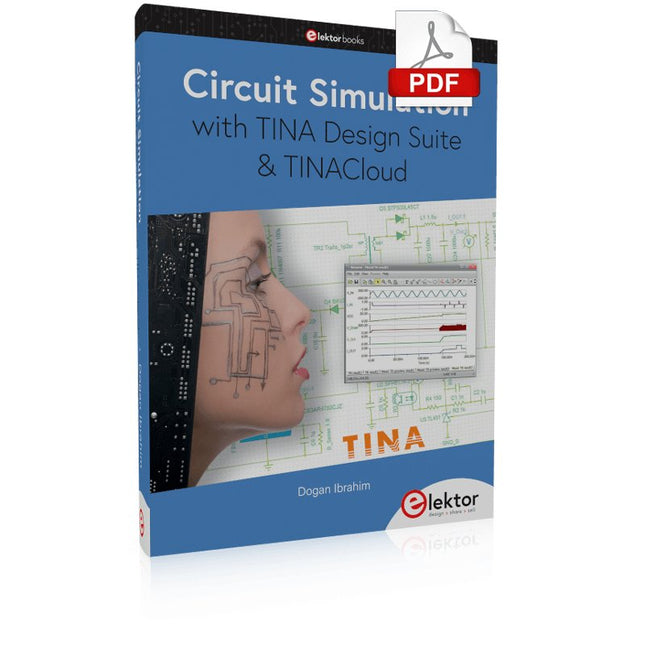
Elektor Digital Circuit Simulation with TINA Design Suite & TINACloud (E-book)
TINA Design Suite is a professional, powerful and affordable circuit simulator. It is a circuit designer and PCB design software package for analysing, designing, and real-time testing of analogue, digital, IBIS, VHDL, Verilog, Verilog AMS, SystemC, MCU, and mixed electronic circuits and their PCB layouts. In this book, top-selling Elektor author, Prof. Dr. Dogan Ibrahim aims to teach the design and analysis of electrical and electronic circuits and develop PCB boards using both TINA and TINACloud. The book is aimed at electrical/electronic engineers, undergraduate electronic/electrical engineering students at technical colleges and universities, postgraduate and research students, teachers, and hobbyists. Many tested and working simulation examples are provided covering most fields of analogue and digital electrical/electronic engineering. These include AC and DC circuits, diodes, zener diodes, transistor circuits, operational amplifiers, ladder diagrams, 3-phase circuits, mutual inductance, rectifier circuits, oscillators, active and passive filter circuits, digital logic, VHDL, MCUs, switch-mode power supplies, PCB design, Fourier series, and spectrum. Readers do not need to have any programming experience unless they wish to simulate complex MCU circuits.
€ 39,95
Mitglieder: € 35,96
-

Elektor Digital The CAN Bus Companion (E-book)
Projects with Arduino Uno & Raspberry Pi with Examples for the MCP2515 CAN Bus Interface Module This book details the use of the Arduino Uno and the Raspberry Pi 4 in practical CAN bus based projects. Using either the Arduino Uno or the Raspberry Pi with off-the-shelf CAN bus interface modules considerably ease developing, debugging, and testing CAN bus based projects. This book is written for students, practicing engineers, enthusiasts, and for everyone else wanting to learn more about the CAN bus and its applications. The book assumes that the reader has some knowledge of basic electronics. Knowledge of the C and Python programming languages and programming the Arduino Uno using its IDE and Raspberry Pi will be useful, especially if the reader intends to develop microcontroller-based projects using the CAN bus. The book should be a useful source of reference material for anyone interested in finding answers to questions such as: What bus systems are available for the automotive industry? What are the principles of the CAN bus? How can I create a physical CAN bus? What types of frames (or data packets) are available in a CAN bus system? How can errors be detected in a CAN bus system and how dependable is a CAN bus system? What types of CAN bus controllers exist? How do I use the MCP2515 CAN bus controller? How do I create 2-node Arduino Uno-based CAN bus projects? How do I create 3-node Arduino Uno-based CAN bus projects? How do I set the acceptance masks and acceptance filters? How do I analyze data on the CAN bus? How do I create 2-node Raspberry Pi-based CAN bus projects? How do I create 3-node Raspberry Pi-based CAN bus projects?
€ 32,95
Mitglieder: € 29,66
-

Sensepeek Sensepeek 6003 PCBite Kit inkl. 4x SQ10-Tastkopf und Prüfkabel
Die freihändigen PCBite-Tastköpfe der SQ-Serie von Sensepeek sind isoliert, werden mit farbcodierten Kabelhaltern geliefert und haben einen niedrigeren Schwerpunkt, wodurch sie im Vergleich zu den Sonden der ursprünglichen SP-Serie noch stabiler sind. Alle beliebten Funktionen der freihändigen Messung, die austauschbare Prüfnadel mit feiner Steigung und das minimalistische Design werden beibehalten, um herkömmliche und handgehaltene Sonden überflüssig zu machen. Features Alle freihändigen Tastköpfe von Sensepeek machen sofortige Messungen oder lange Triggersitzungen zum Kinderspiel. Keine Lötdrähte mehr zum Anschließen Ihres Tastkopfs oder komplizierte Werkzeuge zum Einrichten, sondern einfach die Sondennadel auf einem beliebigen Testpunkt oder einer beliebigen Komponente im Signalpfad positionieren und loslassen. Spart Zeit und Frust bei der Entwicklung, Überprüfung und Reparatur. Das minimalistische Design und die federbelastete Prüfnadel ermöglichen die gleichzeitige Messung von Fine-Pitch-Komponenten und nahegelegenen Signalen. Sowohl Länge als auch Gewicht der SQ-Tastköpfe sind perfekt ausbalanciert, um mit den mitgelieferten PCB-Haltern und der Grundplatte verwendet zu werden, was ein Muss für die Freisprechfunktion ist. Der Sondenhalter wird wie alle PCBite-tastköpfe und -Halter mit einem starken Magneten in der Basis geliefert, wodurch die Tastköpfe leicht zu platzieren und neu zu positionieren ist. Die Tastköpfe der SQ-Serie können ohne den Sondenhalter in der Hand verwendet werden, da sie einen isolierten Griff haben, aber ihr volles Potenzial wird beim Freihandmessen genutzt. Eine Seite der mitgelieferten Grundplatte ist matt und die andere hochglanzpoliert. Die hochglanzpolierte Oberfläche macht es einfach, Komponenten auf der Unterseite der Leiterplatte zu sehen. Für zusätzlichen Schutz während der Messung kann die mitgelieferte Isolierabdeckung auf einer der Oberflächen montiert werden. Lieferumfang 4x PCBite Platinenhalter 1x Satz gelbe Isolierscheiben für die Platinenhalter 1x große Grundplatte (A4) 1x Isolierabdeckung für die Bodenplatte (A4) 1x Mikrofasertuch 4x SQ10 Tastköpfe und Prüfnadeln mit Stiftspitze (schwarz) 2x Bananen-zu-Dupont-Prüfkabel (rot/schwarz) 5x Dupont-zu-Dupont-Prüfkabel 1x Kabelhalter-Set (4 Farben) 4x Extra Testnadeln Downloads User guide (PCBite kit) User guide (SQ10 probes)
€ 177,31
-

Siglent Siglent SDS822X HD 2-Kanal Oszilloskop (200 MHz)
The Siglent SDS822X HD digital storage oscilloscope is based on 2 GSa/s, 12-bit Analog-Digital Converters and front ends with excellent noise floor performance. With a 200 MHz bandwidth, and a maximum record length of 100 Mpts, and the capability to analyze 2 analog channels alongside 16 digital channels, the SDS822X HD is perfectly suited for mixed signal analysis. Features 12-bit High Resolution 12-bit Analog-Digital Convertors with sample rate up to 2 GSa/s Front ends with 70 μVrms noise floor @ 200 MHz bandwidth 2/4 analog channels, up to 700 MHz bandwidth SPO technology Waveform capture rate up to 120,000 wfm/s (normal mode), and 500,000 wfm/s (sequence mode) Supports 256-level intensity grading and color temperature display modes. Up to 50 Mpts record length Digital trigger system Intelligent trigger: Edge, Slope, Pulse width, Window, Runt, Interval, Dropout, Pattern, Video (HDTV supported), Qualified, Nth edge, Delay, Setup/Hold time. Serial bus triggering and decoder, supports protocols I²C, SPI, UART, CAN, LIN. Segmented acquisition (Sequence) mode, dividing the maximum record length into multiple segments (up to 80,000), according to trigger conditions set by the user, with a very small dead time between segments to capture the qualifying event. History waveform record (History) function, the maximum recorded waveform length is 80,000 frames. Automatic measurements on 50+ parameters, supports statistics with histogram, track, trend, Gating measurement, and measurements on Math, History and Ref. 4 Math traces (2 Mpts FFT, addition, subtraction, multiplication, division, integration, differential, square root, etc.), supports formula editor. Abundant data analysis functions such as Search, Navigate, Counter, Bode plot and Power Analysis High Speed hardware-based Mask Test function, with Mask Editor tool for creating user-defined masks 16 digital channels (optional) 25 MHz waveform generator (optional) 7" TFT-LCD display with 1024 x 600 resolution; Capacitive touch screen supports multi-touch gestures. Interfaces include: USB Hosts, USB Device (USBTMC), LAN (VXI-11/Telnet/Socket), Pass/Fail, Trigger Out Built-in web server supports remote control over the LAN port using a web browser. Supports SCPI remote control commands. Supports external mouse and keyboard. Supports NTP. Technische Daten Analog Channels 2 Bandwidth 200 MHz Vertical resolution 12-bit Sample rate (Max.) One channel mode: 100 Mpts/chTwo channel mode: Mpts/chFour channel mode: 25 Mpts/ch Memory depth (Max.) One channel mode: 50 Mpts/chTwo channel mode: 25 Mpts/ch Waveform capture rate (Max.) Normal mode: 120,000 wfm/sSequence mode: 500,000 wfm/s Trigger type Edge, Slope, Pulse width, Window, Runt, Interval, Dropout, Pattern, Video, Qualified, Nth edge, Delay, Setup/Hold time, Serial Serial trigger and decode (Standard) I²C, SPI, UART, CAN, LIN Measurement 50+ parameters, statistics, histogram, trend, and track supported Math 4 traces 2 Mpts FFT, Filter, +, -, x, ÷, ∫dt, d/dt, √, Identity, Negation, Absolute, Sign, ex, 10x, ln, lg, Interpolation, MaxHold, MinHold, ERES, Average. Supports formula editor Data analysis Search, Navigate, History, Mask Test, Counter, Bode plot, and Power Analysis Digital channel (optional) 16-channel; maximum sample rate up to 1 GSa/s; record length up to 10 Mpts USB AWG module (option) One channel, 25 MHz, sample rate of 125 MHz, wave length of 16 kpts, isolated output I/O 2x USB 2.0 Host, USB 2.0 Device, 10/100 M LAN, Auxiliary output (TRIG OUT, PASS/FAIL), SBUS (Siglent MSO) Probe (Standard) Passive probe PB470 for each channel Display 7 TFT-LCD with capacitive touch screen (1024x600) Lieferumfang 1x Siglent SDS822X Oscilloscope 2x Passive probe (200 MHz) PP520 1x Power cord (EU) 1x USB cable 1x Certificate of calibration 1x Quick start Downloads Datasheet Manual Programming guide
€ 635,25
Bestpreis
-
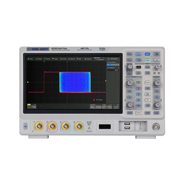
Siglent Siglent SDS2354X Plus 4-Kanal Oszilloskop (350 MHz)
Die digitalen Speicheroszilloskope der SDS2000X Plus-Serie von Siglent sind in Bandbreiten von 100 MHz, 200 MHz und 350 MHz erhältlich, haben eine maximale Abtastrate von 2 GSa/s, eine maximale Aufzeichnungslänge von 200 Mpts/Kanal und bis zu 4 analoge Kanäle + 16 digitale Kanäle, Mixed-Signal-Analysefähigkeit. Die SDS2000X Plus-Serie nutzt die SPO-Technologie von Siglent mit einer maximalen Wellenformerfassungsrate von bis zu 120.000 wfm/s (Normalmodus, bis zu 500.000 wfm/s im Sequenzmodus), einer Anzeigefunktion mit 256 Intensitätsstufen sowie einer Farbtemperatur Anzeigemodus. Es verwendet außerdem ein innovatives digitales Triggersystem mit hoher Empfindlichkeit und geringem Jitter. Das Triggersystem unterstützt mehrere leistungsstarke Triggermodi, einschließlich serieller Bus-Triggerung. Verlaufsaufzeichnung von Wellenformen, Sequenzerfassung sowie Such- und Navigationsfunktionen ermöglichen die Erfassung, Speicherung und Analyse erweiterter Wellenformaufzeichnungen. Eine beeindruckende Auswahl an Mess- und Mathematikfunktionen, Optionen für einen 50-MHz-Wellenformgenerator sowie serielle Dekodierung, Maskentest, Bode-Plot und Leistungsanalyse sind weitere Merkmale des SDS2000X Plus. Ein 10-Bit-Erfassungsmodus hilft dabei, Anwendungen zu erfüllen, die eine Auflösung von mehr als 8 Bit erfordern. Der große kapazitive 10,1"-Touchscreen unterstützt Multi-Touch-Gesten, während die Remote-Websteuerung sowie die Unterstützung für Maus und externe Tastatur die Bedieneffizienz des SDS2000X Plus erheblich verbessern. Features Erhältlich mit 100 MHz, 200 MHz, 350 MHz Bandbreite (aufrüstbar auf 500 MHz) Echtzeit-Abtastrate bis zu 2 GSa/s Aufzeichnungslänge bis zu 200 Mpts Serieller Bus-Trigger und Decoder, unterstützt I²C, SPI, UART, CAN, LIN, CAN FD, FlexRay, I²S und MIL-STD-1553B Bietet 10-Bit-Modus, vertikalen und horizontalen Zoom Der kapazitive Touchscreen unterstützt Multi-Touch-Gesten Siglent SDS2000X Plus Oszilloskope SDS2102X Plus SDS2104X Plus SDS2204X Plus SDS2354X Plus Bandbreite 100 MHz 100 MHz 200 MHz 350 MHz Kanäle 2 4 4 4 Echtzeit-Abtastrate 2 GSa/s 2 GSa/s 2 GSa/s 2 GSa/s Erfassungsrate 120,000 wfm/s 120,000 wfm/s 120,000 wfm/s 120,000 wfm/s Speichertiefe 200 Mpts/ch 200 Mpts/ch 200 Mpts/ch 200 Mpts/ch Lieferumfang Siglent SDS2354X Plus Oszilloskop Passive Sonden Netzkabel USB-Kabel Manual Downloads Datasheet Manual Quick guide User manual Firmware
€ 2.474,25
-

Elektor Labs Elektor Rauscharmes Labornetzteil
Das rauscharme Labornetzteil von Elektor ist ein vollständig analoges, einstellbares, symmetrisches Gerät mittlerer Leistung, das ohne Schalt- oder digitale Komponenten auskommt. Es bietet eine Ausgangsspannung, die zwischen 0 V und ±22 V einstellbar ist, sowie einen Ausgangsstrom, der von 0 A bis 1 A eingestellt werden kann. Da auf jegliche Art von Schalttechnik verzichtet wird, liefert das Design extrem geringes Rauschen. Zur Anzeige beider Ausgangsspannungen und -ströme werden vier kleine analoge Einbauinstrumente mit Drehspulmesswerk verwendet. Die meisten modernen Labornetzgeräte und AC-Adapter arbeiten mit Schaltnetzteiltechnik. Selbst die besten Ausführungen weisen zwangsläufig hochfrequente Restwelligkeit und andere Schaltartefakte am Ausgang auf, die die Prüfung empfindlicher analoger Schaltungen stören und Messungen kleiner Signale beeinträchtigen können. Um dieses Problem zu vermeiden, setzt dieses Konzept auf ein vollständig analoges Netzgerät. Obwohl es weniger effizient ist als vergleichbare Schaltnetzteile, spielt die geringere Effizienz beim Einsatz auf dem Prüfstand kaum eine Rolle und sorgt für sauberere und zuverlässigere Messergebnisse. Da viele analoge Schaltungen eine symmetrische Versorgung benötigen, liefert dieses Design positive und negative Ausgangsspannungen gleicher Höhe. Eine geringfügige Nachjustierung ist möglich, um eventuelle Ungleichgewichte auszugleichen. Selbstverständlich ist auch eine einstellbare Strombegrenzung integriert. Das Kit enthält die für den Aufbau des Netzteils erforderlichen Komponenten, mit Ausnahme der Transformatoren. Technische Daten Ausgangsspannung 0…+22 V, 0, −22 V Ausgangsstrom 0…+1 A, 0…−1 A Rauschen −85 dBV (bei 0,95 A/20 V, B = 22 kHz) −84 dBV (bei 0,95 A/20 V, B > 500 kHz) Restwelligkeit 50 µVRMS (bei 950 mA/20 V, B = 22 kHz, hauptsächlich 100-Hz-Anteil) Lieferumfang 3x Platinen: Regler (PCB-1), Netzfilter (PCB-2) und Transformator (PCB-3) Alle Bauteile mit Ausnahme der Netztransformatoren 4x Drehspulmesswerke Zusätzliche Teile für die Verdrahtung (Drähte, Bananenbuchsen, Kaltgeräte-Netzmodul usw.) Nicht enthalten Die drei Netztransformatoren Ein Gehäuse Stückliste Für die Spannungsregler-Platine (240386-1) Widerstände (250 mW, 1%) R1 = 12 Ω R2, R8, R37, R62 = 1 MΩ R3, R7, R10, R13, R17, R20, R22, R30, R35, R42, R45, R47, R55, R60 = 100 Ω, 600 mW R4, R5 = 4.7 kΩ R6 = 100 kΩ R9, R12, R14, R36, R38, R39, R61, R63, R66, R72, R78, R79 = 10.0 kΩ, 600 mW R11 = 9.76 kΩ, 600 mW R15, R40 = 44.2 kΩ, 600 mW R16, R41, R77 = 1 kΩ R18, R43 = 1.5 kΩ, 1 W, 5% R19, R44 = 470 Ω, 1 W, 5% R21, R46 = 330 Ω, 600 mW R23, R24, R48, R49 = 1.0 Ω, 1 W R25, R50 = 1 kΩ, 1 W, 5% R26, R28, R51, R53 = 1.000 kΩ 0.1%, 15 ppm/C R27, R29, R52, R54 = 10.00 kΩ 0.1%, 15 ppm/C R31, R56 = 1.2 kΩ, 1 W, 5% R32, R57 = 47 kΩ R33, R58 = 270 Ω R34, R59 = 27 kΩ R64, R69 = 12.0 kΩ R65 = 3.0 kΩ, 600 mW R67, R80 = 470 Ω, 600 mW R68, R70 = 6.8 kΩ, 600 mW R71 = 30.0 kΩ,, 600 mW R73, R74, R75, R76 = 10 MΩ P1, P2, P3 = 10 kΩ, 200 mW, 20%, potentiometer, 1 turns, single, lin., panel mount P4, P5 = 500 Ω, 500 mW, 10%, trimmer, 25 turns, 3296Y-1-501LF Bourns P6, P7 = 10 kΩ, 500 mW, 10%, trimmer, 25 turns, 3296Y-1-501LF Bourns Kondensatoren C1 = 100 nF, 50 V, 10%, ceramic X7R, LS 5 mm C2, C3, C6, C7, C30 = 10 µF, 63V, 20%, LS 2.5 mm, 3000hours@105°C C4, C5, C8, C9, C13, C14, C18, C19, C23, C24, C28, C29, C31, C32, C38, C39 = 100 nF, 250 V, 10%, PET, LS 7.5 mm C10, C20 = 47 nF, 100 V, 5%, PET, LS 5 mm C11, C21 = 10 nF, 100 V, 5%, PET, LS 5 mm C12, C22 = 220 µF, 35 V, 20%, 0.024 Ω, LS2.5/3.5 mm, Ir 3.4 A, 2000hours@125°C, polymer C15, C25 = 120 µF, 50 V, 20%, ESR 0.02 Ω, Diam. 10 mm max., LS 5 mm C16, C26 = 15 nF, 100 V, 5%, PET, LS 5 mm C17, C27 = 47 nF, 100 V, 5%, PET, LS 5 mm C33, C34 = 22 µF, 50 V, 20%, LS 2 mm, 10000 hours @ 105°C C35, C36, C44, C45 = 1 µF, 100 V, 10%, LS 5 mm, ceramic X7R C37 = 100 uF, 50 V, 20%. LS 3.5 mm C40, C41, C42, C43, C46, C47, C48, C49 = 1000 µF, 50 V, 20%, LS 5/7.5 mm, Ir 3.32 A, 10000hours@105°C, D 16 mm C50, C51, C52, C53 = 47 nF, 100 V, 10%, ceramic X7R, LS 5 mm Induktivitäten L1, L2 = 4.7 µH, 3.2 A, 0.033 Ω, LS 5 mm, RLB0914-4R7ML Bourns L3 = Commom mode choke, 14.5 mH, 3 A, SSRH24NH-30145 Kemet Halbleiter D1, D2, D3, D4, D5, D9, D10, D11, D15 = BAT85, DO-34 D6, D7, D12, D13 = SR560, DO-201AD D8, D14, D16 = 1N4148, DO-35 D17 = Zenerdiode, 5.6 V, 0.5 W, DO-41 D18, D19 = 1N4004, DO-41 D20, D21 D22, D23 = V30100CI-M3/P, dual common cathode, TO-220 D24 = Zener diode, 30 V, 1 W, DO-41 LED1, LED2 = LED, red, T-1 (3 mm) LED3, LED4 = LED, green, T-1 (3 mm) TVS1, TVS2 = BZW50-33B, R6 T1, T2, T4 = BC337.25, TO-92 T3 = NJW0302G, TO-3P T5, T6, T8 = BC327.25, TO-92 T7 = NJW0281G, TO-3P T9 = BD139, TO-126 (SOT-32) IC1 = LM334Z, TO-92 IC2 = LM4040AIZ-5.0/NOPB, TO-92 (TO-226AA-3) IC3, IC4 = OPA2992IDR, SOIC-8 IC5, IC6 = OPA4992IDR, SOIC-14 IC7 = OPA992IDBVR, SOT-23-5 IC8 = LM339N, DIP-14 IC9 = LM317, TO-220 IC10 = LM337, TO-220 Sonstiges F1, F2 = 5×20 mm fuse, 1.6 A, fast acting HS1, HS2 = Heatsink MC33271 (for T3/T7), 2.7°C/W, PCB mount, height 63.5 mm K1, K4 = 3-way screw terminal block, LS 3.5 mm, max. 1.5 mm² K2, K3 = 3-way screw terminal block, LS 3.5 mm, max. 1 mm² M1, M3 = Moving coil meter, Range 30 V, type 91C4, 45×45 mm M2, M4 = Moving coil meter, Range 1 A, type 91C4, 45×45 mm² RE1 = Relay DPDT,5V, UA2-5NU Verschiedenes 3× 3-way screw terminal block, LS 3.5 mm, max. 1 mm² (for P1, P2, P3) 4× Pin header, 1×2, vertical, pitch 2.54 mm (for LED1, LED2, LED3, LED4) 4× Pin socket, 1×2, vertical. pitch 2.54 mm (for LED1, LED2, LED3, LED4) 2× Heatsink FK222SA220, 20°C/W, PCB mount (for IC9 & IC10) 2× Mica thermal pad for TO-220, 12×18×0.05 mm (for IC9 & IC10) 2× Insulating bushing IB 6, TO-220 (for IC9 & IC10) 2× Ceramic thermal pad, 23×20×2 mm (for T3 & T7) 2× PCB Fuse Holder, for 5×20 mm fuse, 10 A (for F1, F2) 2× Cover for PCB Fuse Holder, transparent (for F1, F2) 2× 2-way screw terminal block, LS 3.5 mm, max. 1 mm² (for M1 & M3) 2× 2-way screw terminal block, LS 3.5 mm, max. 1.5 mm² (for M2 & M4) 8× M3 solder lug, thickness 0.35 mm (for M1…M4) M4 solder lug, thickness 0.35 mm (to connect 4 mm banana connectors) Screened cable, 1 pair, 2×24 AWG/0.22 mm², 1 m (for P1, P2 & P3) IC socket, DIP, 14 contacts (for IC8) M3 washer, plain, steel M3 screw, 16 mm, steel, pan head M3 nut M3 spring washer 50 mm M3 standoff, steel, male-female 12 mm M3 standoff, steel, male-female 10 mm M3 standoff, steel, male-female M3 screw, 8 mm, steel, pan head Für die Netzfilter-Platine (240386-2) Widerstand R1 = 220 kΩ, 1 W, 500 V, 5% Kondensatoren C1, C2 = 470 nF, 305 VAC, Class X2, 11 × 27 mm max., LS 15/22.5 mm C3, C4, C5, C6 = 2.2 nF, 300 VAC, Class Y2, 13 × 4 mm, LS 10 mm, PP Induktivitäten L1, L2 = Common-mode choke, 6.8 mH, 1.7 A, TDK B82732R2172B030 Halbleiter MOV1 = TVS varistor, 300 VAC, S14K300 (230 VAC, B72214S0301K101) and SK14K150 (150 VAC, B72214S0151K101) Sonstiges K1, K2 = 3-way screw terminal block, LS 7.62 mm F1 = Time-delay fuse, 0.5 A (230 VAC) or 1 A (115 VAC) Verschiedenes 1× Fuse holder, 5×20 mm, 10 A, 500 VAC 1× Transparent fuse cover 4× 10 mm M3 standoff, steel, male–female 4× M3 screw, 8 mm, steel, pan head 4× M3 nut Für die Transformator-Platine (240386-3) Widerstände R1, R2 = 2.7 kΩ, 600 mW, 1% R3 = 10.0 kΩ, 600 mW, 1% Kondensator C1 = 220 µF, 50 V, 20%, Ø10 mm, LS 5 mm, 4000 h @ 105°C Transformatoren (nicht im Lieferumfang dieses Kits enthalten!) TR1, TR2, TR3 = 2×7 V, 25 VA, PCB-mounted toroid, 70060K Talema Halbleiter D1–D4 = 1N4148, DO-35 D5, D6 = 1N4004, DO-41 D7 = Zener 5.6 V, 1.3 W, DO-41 LED1 = LED, red, T-1 (3 mm) IC1, IC2 = MOC8021M, CTR ≥ 1000%, DIP-6 Sonstiges F1, F2, F3 = 160 mA time-delay fuse (230 VAC) or 315 mA time-delay fuse (115 VAC) K1 = 2-way screw terminal block, LS 7.62 mm K2 = 3-way screw terminal block, LS 3.5 mm, max 1.5 mm² K3, K4 = 3-way screw terminal block, LS 3.5 mm, max 1 mm² RE1, RE2 = Relay DPDT, 5 A/250 VAC / 24 VDC Verschiedenes 1× Pin header 1×2, pitch 2.54 mm + matching socket for LED1 3× Fuse holder 5 × 20 mm, 10 A, 500 VAC + transparent cover 3× M4 screw, 8 mm, pan head + washer for TR1-TR3 8× M3 screw, 8 mm, pan head + nut + washer 8× 10 mm M3 standoff, steel, male–female 2× IC socket, DIP-6 for IC1 & IC2 Weitere Bauteile 1 m red insulated wire, stranded, 1.5 mm² 0.5 m blue insulated wire, stranded, 1.5 mm² 0.5 m black insulated wire, stranded, 1.5 mm², 0.5 m 2 m red insulated wire, stranded, D 0.56 mm (0.25 mm²) 2 m black insulated wire, stranded, D 0.56 mm (0.25 mm²) 0.5 m Multicore Cable, Flexible, 3 Core, 0.75 mm² (24 x 0.2 mm) Red banana socket Black banana socket Blue banana socket Green banana socket IEC Power Entry Module with switch, IEC C14 3 crimp terminals, FASTON, 4.75 x 0.81 mm 3 knobs Links Elektor Labs JumpStarter Page Artikel (Teil 1) Artikel (Teil 2)
€ 299,00€ 249,00Bestpreis
-
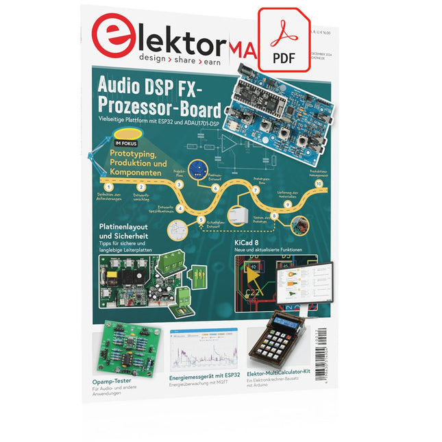
Elektor Digital Elektor 11-12/2024 (PDF)
Diese Ausgabe steht allen GOLD- und GREEN-Mitgliedern auf der ElektorMagazine-Website zum Download bereit! Sie sind noch kein Mitglied? Hier klicken! Audio-DSP-FX-Prozessor-BoardTeil 1: Eigenschaften und Design 50 Jahre Elektor in englischer Sprache KiCad 8Neue und aktualisierte Funktionen MultiCalculator-KitEin Elektronikrechner-Bausatz von Elektor mit Arduino Preiswerte GNSS-RTK-SystemeFür zentimetergenaue Positionsbestimmung Platinenlayout und SicherheitTipps für sichere und langlebige Leiterplatten Opamp-TesterFür Audio- und andere Anwendungen Projekt-Update #4 : Energiemessgerät mit ESP32Energieüberwachung mit MQTT Echtzeit-Spektrumanalyzer mit Waveguide-Technologie und Multi-Schnittstellen-PCsAaronia etabliert neues Produktsegment und präsentiert erste Prototypen auf der electronica in München electronica 2024Highspeed und robuste Board-to Board Steckverbinder InduktivitätenSpulen und Ferrite anwendungsorientiert selektieren EMI-Abschirmung zur Einhaltung der elektromagnetischen Konformität Das ultimative Werkzeug für jeden Elektronik-EnthusiastenUnendliche Möglichkeiten mit Red Pitaya und 1.000+ Click Boards™ Die 100 % durchgängige Flussmittelseele Siglent stellt seine neue Vektornetzwerkanalysator-Plattform SNA6000A vor HDI der MittelklasseEin neuer ökonomischer PCB Pooling Service für hochpolige BGAs Ferngesteuerte IoT-EntwicklungDie einzige Lösung für Fernunterricht und Entwicklung in der Embedded-Industrie Herausforderungen der DFM-Analyse für Flex- und Rigid-Flex-Design Aus dem Leben gegriffenMikrotechnophobie Feliz Natal: 3D-WeihnachtsbaumEine 3D-Platine mit preiswertem 32-Bit-Mikrocontroller Aller Anfang......muss nicht schwer sein: Weiter geht es mit den Opamps! Ein autonomer SensorknotenProjekt-Update #1: Reduzierung der Leerlauf-Stromaufnahme mit externer RTC mit Leistungsschalter 2024: Eine Odyssee in die KIEin Blick zurück in die Zukunft LED-Displays mit dem MAX7219Ein praktischer Ansatz für einen großartigen Chip Projekt 2.0Korrekturen, Updates und Leserbriefe VibroTactile-HandschuheEin Durchbruch für Parkinson-Patienten?
€ 11,90
-
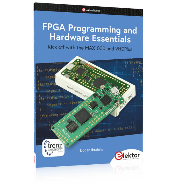
Elektor Publishing FPGA Programming and Hardware Essentials
Kick off with the MAX1000 and VHDPlus Ready to Master FPGA Programming? In this guide, we’re diving into the world of Field Programmable Gate Arrays (FPGAs) – a configurable integrated circuit that can be programmed after manufacturing. Imagine bringing your ideas to life, from simple projects to complete microcontroller systems! Meet the MAX1000: a compact and budget-friendly FPGA development board packed with features like memory, user LEDs, push-buttons, and flexible I/O ports. It’s the ideal starting point for anyone wanting to learn about FPGAs and Hardware Description Languages (HDLs). In this book, you’ll get hands-on with the VHDPlus programming language – a simpler version of VHDL. We’ll work on practical projects using the MAX1000, helping you gain the skills and confidence to unleash your creativity. Get ready for an exciting journey! You’ll explore a variety of projects that highlight the true power of FPGAs. Let’s turn your ideas into reality and embark on your FPGA adventure – your journey starts now! Exciting Projects You’ll Find in This Book Arduino-Driven BCD to 7-Segment Display Decoder Use an Arduino Uno R4 to supply BCD data to the decoder, counting from 0 to 9 with a one-second delay Multiplexed 4-Digit Event Counter Create an event counter that displays the total count on a 4-digit display, incrementing with each button press PWM Waveform with Fixed Duty Cycle Generate a PWM waveform at 1 kHz with a fixed duty cycle of 50% Ultrasonic Distance Measurement Measure distances using an ultrasonic sensor, displaying the results on a 4-digit 7-segment LED Electronic Lock Build a simple electronic lock using combinational logic gates with push buttons and an LED output Temperature Sensor Monitor ambient temperature with a TMP36 sensor and display the readings on a 7-segment LED Downloads Software
€ 39,95
Mitglieder: € 35,96
-

Siglent Siglent SDS2102X Plus 2-Kanal Oszilloskop (100 MHz)
Die digitalen Speicheroszilloskope der SDS2000X Plus-Serie von Siglent sind in Bandbreiten von 100 MHz, 200 MHz und 350 MHz erhältlich, haben eine maximale Abtastrate von 2 GSa/s, eine maximale Aufzeichnungslänge von 200 Mpts/Kanal und bis zu 4 analoge Kanäle + 16 digitale Kanäle, Mixed-Signal-Analysefähigkeit. Die SDS2000X Plus-Serie nutzt die SPO-Technologie von Siglent mit einer maximalen Wellenformerfassungsrate von bis zu 120.000 wfm/s (Normalmodus, bis zu 500.000 wfm/s im Sequenzmodus), einer Anzeigefunktion mit 256 Intensitätsstufen sowie einer Farbtemperatur Anzeigemodus. Es verwendet außerdem ein innovatives digitales Triggersystem mit hoher Empfindlichkeit und geringem Jitter. Das Triggersystem unterstützt mehrere leistungsstarke Triggermodi, einschließlich serieller Bus-Triggerung. Verlaufsaufzeichnung von Wellenformen, Sequenzerfassung sowie Such- und Navigationsfunktionen ermöglichen die Erfassung, Speicherung und Analyse erweiterter Wellenformaufzeichnungen. Eine beeindruckende Auswahl an Mess- und Mathematikfunktionen, Optionen für einen 50-MHz-Wellenformgenerator sowie serielle Dekodierung, Maskentest, Bode-Plot und Leistungsanalyse sind weitere Merkmale des SDS2000X Plus. Ein 10-Bit-Erfassungsmodus hilft dabei, Anwendungen zu erfüllen, die eine Auflösung von mehr als 8 Bit erfordern. Der große kapazitive 10,1"-Touchscreen unterstützt Multi-Touch-Gesten, während die Remote-Websteuerung sowie die Unterstützung für Maus und externe Tastatur die Bedieneffizienz des SDS2000X Plus erheblich verbessern. Features Erhältlich mit 100 MHz, 200 MHz, 350 MHz Bandbreite (aufrüstbar auf 500 MHz) Echtzeit-Abtastrate bis zu 2 GSa/s Aufzeichnungslänge bis zu 200 Mpts Serieller Bus-Trigger und Decoder, unterstützt I²C, SPI, UART, CAN, LIN, CAN FD, FlexRay, I²S und MIL-STD-1553B Bietet 10-Bit-Modus, vertikalen und horizontalen Zoom Der kapazitive Touchscreen unterstützt Multi-Touch-Gesten Siglent SDS2000X Plus Oszilloskope SDS2102X Plus SDS2104X Plus SDS2204X Plus SDS2354X Plus Bandbreite 100 MHz 100 MHz 200 MHz 350 MHz Kanäle 2 4 4 4 Echtzeit-Abtastrate 2 GSa/s 2 GSa/s 2 GSa/s 2 GSa/s Erfassungsrate 120,000 wfm/s 120,000 wfm/s 120,000 wfm/s 120,000 wfm/s Speichertiefe 200 Mpts/ch 200 Mpts/ch 200 Mpts/ch 200 Mpts/ch Lieferumfang Siglent SDS2102X Plus Oszilloskop Passive Sonden Netzkabel USB-Kabel Manual Downloads Datasheet Manual Quick guide User manual Firmware
€ 1.069,00€ 855,20Bestpreis
-

Elektor Publishing The CAN Bus Companion
This book details the use of the Arduino Uno and the Raspberry Pi 4 in practical CAN bus based projects. Using either the Arduino Uno or the Raspberry Pi with off-the-shelf CAN bus interface modules considerably ease developing, debugging, and testing CAN bus based projects. This book is written for students, practicing engineers, enthusiasts, and for everyone else wanting to learn more about the CAN bus and its applications. The book assumes that the reader has some knowledge of basic electronics. Knowledge of the C and Python programming languages and programming the Arduino Uno using its IDE and Raspberry Pi will be useful, especially if the reader intends to develop microcontroller-based projects using the CAN bus. The book should be a useful source of reference material for anyone interested in finding answers to questions such as: What bus systems are available for the automotive industry? What are the principles of the CAN bus? How can I create a physical CAN bus? What types of frames (or data packets) are available in a CAN bus system? How can errors be detected in a CAN bus system and how dependable is a CAN bus system? What types of CAN bus controllers exist? How do I use the MCP2515 CAN bus controller? How do I create 2-node Arduino Uno-based CAN bus projects? How do I create 3-node Arduino Uno-based CAN bus projects? How do I set the acceptance masks and acceptance filters? How do I analyze data on the CAN bus? How do I create 2-node Raspberry Pi-based CAN bus projects? How do I create 3-node Raspberry Pi-based CAN bus projects?
€ 39,95
Mitglieder: € 35,96
-

Elektor Publishing PLC Programming with the Raspberry Pi and the OpenPLC Project
ModbusRTU and ModbusTCP examples with the Arduino Uno and ESP8266 Introduction to PLC programming with OpenPLC, the first fully open source Programmable Logic Controller on the Raspberry Pi, and Modbus examples with Arduino Uno and ESP8266 PLC programming is very common in industry and home automation. This book describes how the Raspberry Pi 4 can be used as a Programmable Logic Controller. Before taking you into the programming, the author starts with the software installation on the Raspberry Pi and the PLC editor on the PC, followed by a description of the hardware. You'll then find interesting examples in the different programming languages complying with the IEC 61131-3 standard. This manual also explains in detail how to use the PLC editor and how to load and execute the programs on the Raspberry Pi. All IEC languages are explained with examples, starting with LD (Ladder Diagram) over ST (Structured Control Language) to SFC (Special Function Chart). All examples can be downloaded from the author's website. Networking gets thorough attention too. The Arduino Uno and the ESP8266 are programmed as ModbusRTU or ModbusTCP modules to get access to external peripherals, reading sensors and switching electrical loads. I/O circuits complying with the 24 V industry standard may also be of interest for the reader. The book ends with an overview of commands for ST and LD. After reading the book, the reader will be able to create his own controllers with the Raspberry Pi.
€ 39,95
Mitglieder: € 35,96
-

Elektor Publishing LTspice Essentials
An Introduction to Circuit Simulation LTspice, developed by Analog Devices, is a powerful, fast, and free SPICE simulator, schematic capture, and waveform viewer with a large database of components supported by SPICE models from all over the world. Drawing a schematic in LTspice is easy and fast. Thanks to its powerful graphing features, you can visualize the voltages and currents in a circuit, and also the power consumption of its components and much more. This book is about learning to design and simulate electronic circuits using LTspice. Among others, the following topics are treated: DC and AC circuits Signal diodes and Zener diodes Transistor circuits including oscillators Thyristor/SCR, diac, and triac circuits Operational amplifier circuits including oscillators The 555 timer IC Filters Voltage regulators Optocouplers Waveform generation Digital logic simulation including the 74HC family SPICE modeling LTspice is a powerful electronic circuit simulation tool with many features and possibilities. Covering them all in detail is not possible in a book of this size. Therefore, this book presents the most common topics like DC and AC circuit analysis, parameter sweeping, transfer functions, oscillators, graphing, etc. Although this book is an introduction to LTspice, it covers most topics of interest to people engaged in electronic circuit simulation. The book is aimed at electronic/electrical engineers, students, teachers, and hobbyists. Many tested simulation examples are given in the book. Readers do not need to have any computer programming skills, but it will help if they are familiar with basic electronic circuit design and operation principles. Readers who want to dive deeper can find many detailed tutorials, articles, videos, design files, and SPICE circuit models on the Internet. All the simulation examples used in the book are available as files at the webpage of this book. Readers can use these example circuits for learning or modify them for their own applications.
€ 39,95
Mitglieder: € 35,96


