
Suchergebnisse für "dragino OR lora OR iot OR development OR kit OR 868 OR mhz"
-
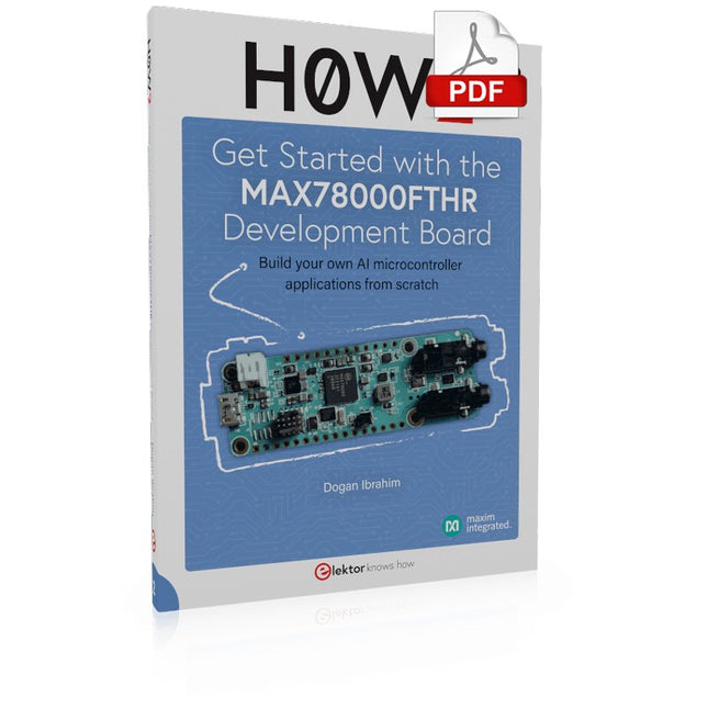
Elektor Digital H0W2: Get Started with the MAX78000FTHR Development Board (E-book)
Build your own AI microcontroller applications from scratch The MAX78000FTHR from Maxim Integrated is a small development board based on the MAX78000 MCU. The main usage of this board is in artificial intelligence applications (AI) which generally require large amounts of processing power and memory. It marries an Arm Cortex-M4 processor with a floating-point unit (FPU), convolutional neural network (CNN) accelerator, and RISC-V core into a single device. It is designed for ultra-low power consumption, making it ideal for many portable AI-based applications. This book is project-based and aims to teach the basic features of the MAX78000FTHR. It demonstrates how it can be used in various classical and AI-based projects. Each project is described in detail and complete program listings are provided. Readers should be able to use the projects as they are, or modify them to suit their applications. This book covers the following features of the MAX78000FTHR microcontroller development board: Onboard LEDs and buttons External LEDs and buttons Using analog-to-digital converters I²C projects SPI projects UART projects External interrupts and timer interrupts Using the onboard microphone Using the onboard camera Convolutional Neural Network
€ 32,95
Mitglieder: € 29,66
-

Elektor Zenerdioden-Tester
Der Elektor Zenerdioden-Tester ist im Wesentlichen eine Konstantstromquelle, die in Stufen von 1 bis 50 mA geschaltet werden kann. Er kann verwendet werden, um Z-Dioden bis zu maximal 54 V zu testen. Dank eines 60-V-Step-up-Wandlers kann das Gerät mit den üblichen 5 bis 12 V versorgt werden. Das Prinzip dieses Testers ist einfach. Eine Z-Diode oder ein anderes DUT (device under test, also ein Prüfling, wie z. B. eine LED) wird über eine einstellbare Stromquelle vorgespannt. Die Spannung über dem DUT kann mit einem Multimeter gemessen werden. Die Spannung der meisten (kleinen) Z-Dioden ist bei einem Strom von 5 mA spezifiziert. Je nach Anwendung kann auch die Spannung bei anderen Strömen interessant sein. Deshalb stehen sechs Stromeinstellungen zur Verfügung: 1, 2, 5, 10, 20 und 50 mA. LEDs sind häufig bei einem Strom von 20 mA spezifiziert. Getestet werden kann: Ob eine Z-Diode defekt ist (Kurzschluss oder hochohmig). Ob eine Z-Diode die korrekte Z-Spannung aufweist. Wie sich eine Z-Spannung bei unterschiedlichen Strömen verändert. Welche exakte Spannung an einer integrierten Spannungsreferenz anliegt. Ob sich LEDs in einer Reihenschaltung in ihrer Helligkeit unterscheiden (daher der Strom von 20 mA). Wie hoch die Stromverstärkung bei unterschiedlichen Basisströmen in (Leistungs-)Transistoren ist. Das Kit enthält alle in der Stückliste aufgeführten Teile, einschließlich Platine und Gehäuse. Technische Daten Versorgungsspannung 5…12 V/2 A (USB-C) Versorgungsstrom (Itest = 50 mA) 1,1 A bei 5 V / 412 mA bei 12 V Wählbare Ströme 1, 2, 5, 10, 20 und 50 mA Max. Prüfspannung >54 V bei Itest ≥1 mA Max. Ausgangsspannung 60 V bei Itest = 0 mA Spannungsbegrenzung bei 5 V 4,5 V bei Itest = 1 mA / 5,18 V bei Itest = 50 mA Gehäuseabmessungen 110 x 82 x 44 mm Platinengröße 105,4 x 67,3 mm Anschlüsse 4-mm-Bananenbuchsen für Multimeter 2-mm-Bananenbuchsen für Prüfklemmen USB-C-Buchse für die Spannungsversorgung Lieferumfang Widerstände R1 = 3.3 kΩ, 600 mW, 1% R2 = 0.15 Ω, 1 W, 5%, LS 12.7 mm, ø 3.5 mm R3, R8 = 180 Ω, 600 mW, 1% R4, R6, R16 = 1 kΩ, 600 mW, 1% R5, R19 = 47 kΩ, 600 mW, 1% R7 = 3.9 kΩ, 1 W, 5%, LS 12.7 mm, ø 3.5 mm R9, R10, R12 = 10 kΩ, 600 mW, 1% R11, R13 = 100 Ω, 600 mW 1% R14 = 249 Ω, 600 mW, 1% R15 = 499 Ω, 600 mW, 1% R17 = 2.49 kΩ, 250 mW, 1% R18 = 4.99 kΩ, 250 mW, 1% Kondensatoren C1 = 470 uF / 35 V, 20%, Ir = 1.86 A, ø 12.5 mm, LS 5 mm, ESR = 0.038 Ω (Panasonic EEUTP1V471) C2 = 1 uF / 100 V, 10%, X7R, LS 5 mm C3 = 2.2 nF / 50 V, 10%, X7R, LS 5 mm C4, C7 = 100 nF / 100 V, 10%, X7R, LS 5 mm C5 = 100 uF / 100 V, 20%, ø 14 mm max., LS 5 mm C6 = 1 nF / 100 V, 10%, X7R, LS 5 mm Induktor L1 = 100 uH, Irms = 2.4 A, Isat = 3.5 A, 0.09 Ω, radial, pitch 2.5/5/10 mm, ø 14 mm max. (Kemet SBC8-101-242) Halbleiter D1 = MUR120G, DO-41 D2, D4 = STPS3150RL, DO-201AD D3 = Z-diode, 18 V, 1.3 W (BZX85C18) D5 = Z-diode, 5.1 V, 0.5 W (1N5231B) LED1 = LED in pushbutton S1 LED2 = LED, green, 3 mm IC1 = MC34063, DIP-8 IC2 = LM4040BIZ-5.0/NOPB, TO-92 (TO-226AA-3) IC3 = TL051CP, DIP-8 T1 = BC327.25, TO-92 T2 = STP40NF10L, TO-220 T3 = IRF9510PBF, TO-220 T4 = 2N7000, TO-92 Sonstiges K1, K2, S1, S3 = 2-way screw terminal block, LS 3.5 mm, max. 1.5 mm² connected to K1 = USB-C socket, 30 V/3 A, chassis mounted, wired, 9 x 16 mm connected to K2 = Banana Connector, 2 mm, Socket, 60 VDC, Panel Mount, red (Multicomp 24.102.1) connected to K2 = Banana Connector, 2 mm, Socket, 60 VDC, Panel Mount, black (Multicomp 24.102.2) Test clip, red, 30 VAC/60 VDC (Hirschmann 931467101) Test clip, black, 30 VAC/60 VDC (Hirschmann 931467100) S1 = Pushbutton, panel mount, SPST-NO, 30 DC/100 mA, with red LED S2 = Rotary Switch, 6 position, 2 pole, 30°, 250 V/150 mA S3 = Toggle switch, panel mount, SPDT, solder lugs, 28 VDC T2, T3 = Heat sink, 15°C/W, FK 214 SA-CB Enclosure Hammond 1591XXSSBK, ABS, 110 x 82 x 44 mm Knob for S2, round shaft 6 mm, ø 21 mm, with indicator line (Multicomp CP-LB21-6-6D) 4 x Self-tapping screw #4-1/4", carbon steel, pan head Banana plug, red, 2 mm, 60 VDC (Multicomp 25.205.1) Banana plug, black, 2 mm, 60 VDC (Multicomp 25.205.2) Banana socket, black 4 mm, panel mount Banana socket, red 4 mm, panel mount for LED1, LED2 = Pin header, 1 x 2, vertical, pitch 2.54 mm for LED1, LED2 = Pin socket, 1 x 2, vertical, pitch 2.54 mm for T2, T3 = M3 screw, 10 mm, steel, pan head 2 x M3 washer, plain, steel 4 x M3 nut for IC1, IC3 = DIP-8 socket Wire, black, 0.25 mm² (24 AWG), stranded 14 x 0.15 mm, 1 m Wire, red, 0.25 mm² (24 AWG), stranded 14 x 0.15 mm, 1 m PCB 250772-1 v1.1 Links Artikel Elektor Labs
€ 99,95€ 79,95Bestpreis
-
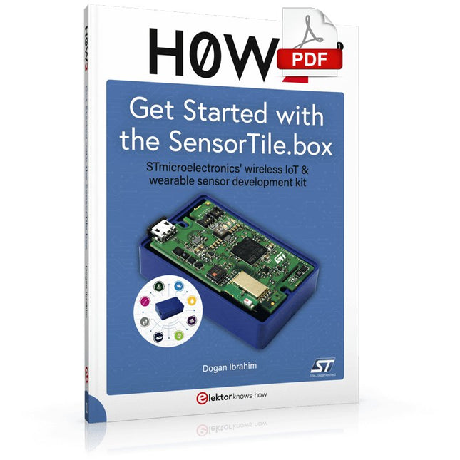
Elektor Digital H0W2: Get Started with the SensorTile.box (E-book)
STmicroelectronics’ wireless IoT & wearable sensor development kit ‘SensorTile.box’ is a portable multi-sensor circuit board housed in a plastic box and developed by STMicroelectronics. It is equipped with a high-performance 32-bit ARM Cortex-M4 processor with DSP and FPU, and various sensor modules, such as accelerometer, gyroscope, temperature sensor, humidity sensor, atmospheric pressure sensor, microphone, and so on. SensorTile.box is ready to use with wireless IoT and Bluetooth connectivity that can easily be used with an iOS or Android compatible smartphone, regardless of the level of expertise of the users. SensorTile.box is shipped with a long-life battery and all the user has to do is connect the battery to the circuit to start using the box. The SensorTile.box can be operated in three modes: Basic mode, Expert mode, and Pro mode. Basic mode is the easiest way of using the box since it is pre-loaded with demo apps and all the user has to do is choose the required apps and display or plot the measured data on a smartphone using an app called STE BLE Sensor. In Expert mode users can develop simple apps using a graphical wizard provided with the STE BLE Sensor. Pro mode is the most complex mode allowing users to develop programs and upload them to the SensorTile.box. This book is an introduction to the SensorTile.box and includes the following: Brief specifications of the SensorTile.box; description of how to install the STE BLE Sensor app on an iOS or Android compatible smartphone required to communicate with the box. Operation of the SensorTile.box in Basic mode is described in detail by going through all of the pre-loaded demo apps, explaining how to run these apps through a smartphone. An introduction to the Expert mode with many example apps developed and explained in detail enabling users to develop their own apps in this mode. Again, the STE BLE Sensor app is used on the smartphone to communicate with the SensorTile.box and to run the developed apps. The book then describes in detail how to upload the sensor data to the cloud. This is an important topic since it allows the sensor measurements to be accessed from anywhere with an Internet connection, at any time. Finally, Pro mode is described in detail where more experienced people can use the SensorTile.box to develop, debug, and test their own apps using the STM32 open development environment (STM32 ODE). The Chapter explains how to upload the developed firmware to the SensorTile.box using several methods. Additionally, the installation and use of the Unicleo-GUI package is described with reference to the SensorTile.box. This PC software package enables all of the SensorTile.box sensor measurements to be displayed or plotted in real time on the PC.
€ 29,95
Mitglieder: € 26,96
-

Elektor Labs USB Logic Analyzer (8 Kanäle, 24 MHz)
Dieser USB Logic Analyzer ist ein 8-Kanal-Logikanalysator, bei dem jeder Eingang doppelt für die analoge Datenaufzeichnung dient. Es eignet sich perfekt zum Debuggen und Analysieren von Signalen wie I²C, UART, SPI, CAN und 1-Wire. Dabei wird ein digitaler Eingang, der mit einem zu testenden Gerät (DUT) verbunden ist, mit einer hohen Abtastrate abgetastet. Die Verbindung zum PC erfolgt via USB.Technische DatenKanäle8 digitale KanäleMaximale Abtastrate24 MHzMaximale Eingangsspannung0 V ~ 5 VBetriebstemperatur0°C ~ 70°CEingangsimpedanz1 MΩ || 10 pFUnterstützte ProtokolleI²C, SPI, UART, CAN, 1-Wire etc.PC-VerbindungUSBAbmessungen55 x 28 x 14 mmLieferumfangUSB Logic Analyzer (8 Kanäle, 24 MHz)USB-KabelJumper Wire Ribbon KabelDownloadsSoftware
€ 19,95
Mitglieder: € 17,96
-
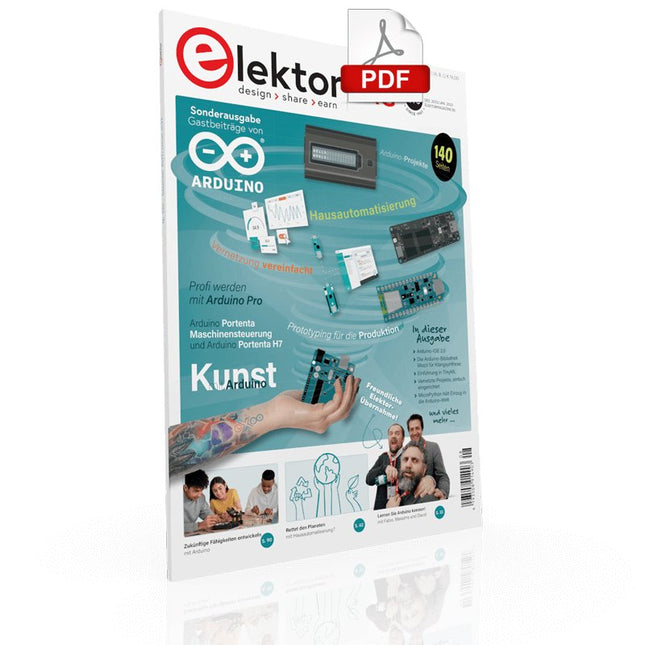
Elektor Digital Elektor-Special: Gastausgabe von Arduino 2022 (PDF)
Diese Ausgabe steht allen GOLD- und GREEN-Mitgliedern auf der ElektorMagazine-Website zum Download bereit! Sind Sie noch kein Mitglied? Hier klicken! Arduino Portenta Machine Control und Arduino Potenta H7 Ein CAN-zu-MQTT Gateway Demo Projekt Ausgepackt: Der Elektor-LCR-Meter-Bausatz von Elektor MicroPython hält Einzug in die Arduino-Welt Vernetzte Projekte, einfach eingerichtet Ihr Weg in die Arduino-Cloud Einführung in TinyML Groß ist nicht immer besser Arduino K-Weg Komfortableres Schreiben von Arduino-Sketches Lernen Sie Arduino kennen! Erste Schritte mit Portenta X8 Sichere Softwareverwaltung mit Containern Skalierbare, sichere Anwendungen erstellen, in Betrieb nehmen und pflegen Arduino Portenta X8 mit dem i.MX 8M Mini-Anwendungsprozessor von NXP und dem EdgeLock Secure Element SE050 Wie ich mein Haus automatisiert habe Arduino-CEO Fabio Violante entwickelt und teilt Lösungen Altair-8800-Emulator Hardware-Simulation eines alten Computers MS-DOS auf dem Portenta-H7-Board Alte Software auf moderner Hardware ausführen Bauen Sie es selbst an Eine digital gesteuerte Anzuchtbox für Indoor-Farming Kann Hausautomatisierung den Planeten retten? MQTT auf dem Arduino Nano RP2040 Connect Professionelle Anwendungen mit Arduino Pro Intelligente Backöfen der nächsten Generation Tagvance sorgt mit Arduino für sicherere Baustellen Santagostino ist da! mit einer Fernüberwachung, die KI für vorausschauende Wartung nutzt Höchste Sicherheit mit der MKR-basierten Lösung von RIoT Secure Eine neue Generation des Wassermanagements mit Open-Source Senso Abholzung mit Schallanalyse aufspüren Die Arduino-Bibliothek Mozzi für Klangsynthese Einblicke von Tim Barrass Das neue Portenta-X8-Board (mit Linux!) und Max Carrier machen es möglich! Wie Arduino Schülern hilft, zukünftige Fähigkeiten zu entwickeln Must-Haves für Ihren Elektronik-Arbeitsplatz Die Bedeutung der Robotik in der Ausbildung Ein zuverlässiges IoT auf Basis von LoRa Ausgepackt: die Portenta-Maschinensteuerung 8-Bit-Gaming mit Arduboy Reduzierung des Wasserverbrauchs auf der Pferderennbahn Ein IoT zur ständigen Überwachung von Bodenfeuchtigkeit und Temperatur Das Panettone-Projekt Ein Robotsystem zur Verwaltung von Sauerteigstartern Unterstützung durch Arduino-Reseller Space Invaders mit Arduino Kunst mit Arduino Inspirierende Einblicke von Künstlern und Designern Arduino-Produktkatalog Die Zukunft von Arduino David und Fabio orakeln
€ 11,90
-
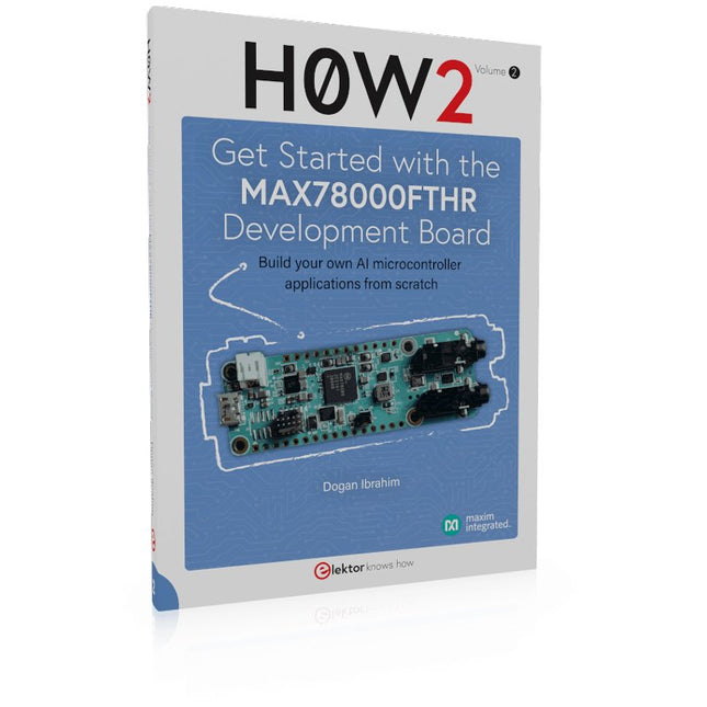
Elektor Publishing H0W2: Get Started with the MAX78000FTHR Development Board
Build your own AI microcontroller applications from scratch The MAX78000FTHR from Maxim Integrated is a small development board based on the MAX78000 MCU. The main usage of this board is in artificial intelligence applications (AI) which generally require large amounts of processing power and memory. It marries an Arm Cortex-M4 processor with a floating-point unit (FPU), convolutional neural network (CNN) accelerator, and RISC-V core into a single device. It is designed for ultra-low power consumption, making it ideal for many portable AI-based applications. This book is project-based and aims to teach the basic features of the MAX78000FTHR. It demonstrates how it can be used in various classical and AI-based projects. Each project is described in detail and complete program listings are provided. Readers should be able to use the projects as they are, or modify them to suit their applications. This book covers the following features of the MAX78000FTHR microcontroller development board: Onboard LEDs and buttons External LEDs and buttons Using analog-to-digital converters I²C projects SPI projects UART projects External interrupts and timer interrupts Using the onboard microphone Using the onboard camera Convolutional Neural Network
€ 39,95
Mitglieder: € 35,96
-

Rigol Rigol DSA815-TG Spektrum-Analyzer (9 kHz – 1,5 GHz)
Highlights Frequenz: 1,5 GHz DANL: -155 dBm Phasenrauschen: -80 dBc/Hz RBW: 10 Hz Tracking-Generator Technische Daten Volldigitale ZF-Technologie Frequenzbereich von 9 kHz bis 1,5 GHz Mindest. -161 dBm Angezeigter durchschnittlicher Geräuschpegel (typisch) Mindest. < -98 dBc/Hz bei 10 kHz Offset-Phasenrauschen Pegelmessunsicherheit < 0,8 dB 10 Hz Mindestauflösungsbandbreite Bis zu 1,5 GHz Tracking-Generator Erweiterte Messfunktionen (Opt.) EMI-Filter und Quasi-Peak-Detektor-Kit (Opt.) VSWR-Messkit (Opt.) PC-Software (Opt.) Optionales RF-TX/RX-Trainingskit Optionales HF-Zubehör (Kabel, Adapter, Dämpfungsglied, Brücke...) Vollständige Konnektivität: LAN (LXI), USB-Host und -Gerät, GPIB (Opt.) 8-Zoll-WVGA-Display (800 x 480). Kompakte Größe, leichtes Design Lieferumfang 1x Rigol DSA815-TG Spektrumanalysator 1x Netzkabel 1x USB-Kabel
€ 1.082,95€ 974,66Bestpreis
-

Elektor Labs Elektor Laserkopf-Upgrade für Sanduhr
Der Elektor Laserkop verwandelt die Elektor Sanduhr in eine Uhr, die die Zeit auf eine im Dunkeln leuchtende Folie statt auf Sand schreibt. Neben der Anzeige der Zeit können damit auch flüchtige Zeichnungen erstellt werden. Der 5-mW-Laserpointer mit einer Wellenlänge von 405 nm erzeugt leuchtend grüne Zeichnungen auf der im Dunkeln leuchtenden Folie. Um optimale Ergebnisse zu erzielen, verwenden Sie das Kit in einem schwach beleuchteten Raum. Achtung: Schauen Sie niemals direkt in den Laserstrahl! Der Bausatz enthält alle notwendigen Komponenten, es ist jedoch das Anlöten von drei Drähten erforderlich. Hinweis: Dieses Kit ist auch mit der originalen Arduino-basierten Sanduhr aus dem Jahr 2017 kompatibel. Weitere Einzelheiten finden Sie unter Elektor 1-2/2017 und Elektor 1-2/2018.
€ 34,95€ 24,95Bestpreis
-
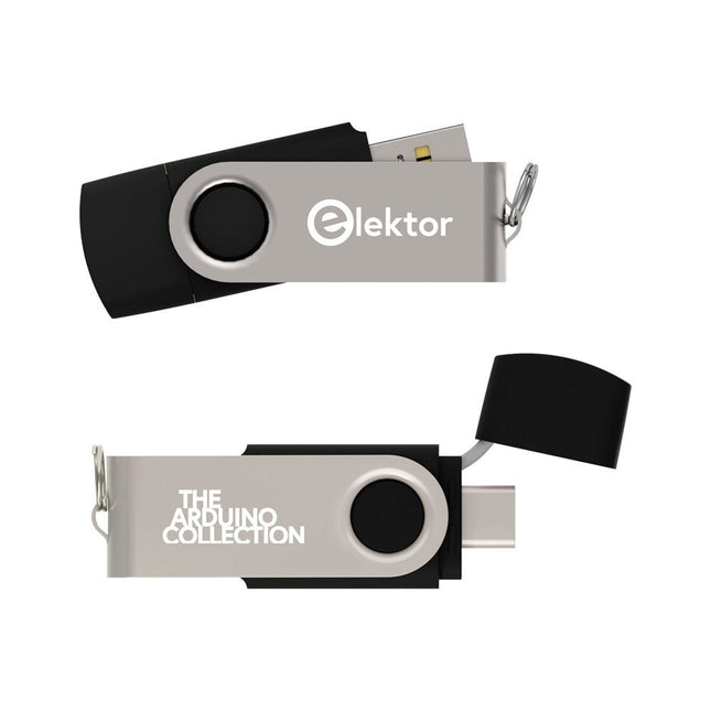
Elektor Classics The Elektor Arduino Collection (USB-Stick)
Dieser USB-Stick enthält eine Auswahl von über 300 Arduino-bezogenen Artikeln, die im Elektor-Magazin veröffentlicht wurden. Der Inhalt umfasst sowohl Hintergrundartikel als auch Projekte zu folgenden Themen: Software- und Hardware-Entwicklung: Tutorials zur Arduino-Softwareentwicklung mit der Arduino IDE, Atmel Studio, verschiedenen Shields und grundlegenden Programmierkonzepten. Lernen: Das Mikrocontroller-Bootcamp bietet einen strukturierten Einstieg in die Programmierung eingebetteter Systeme. Datenerfassung und -messung: Projekte wie ein 16-Bit-Datenlogger, ein Drehbank-Tachometer und ein AC-Netzanalyzer ermöglichen die Erfassung und Analyse von Echtzeitsignalen. Drahtlose Kommunikation: Erfahren Sie, wie man drahtlose Netzwerke implementiert, eine Android-Schnittstelle erstellt und effektiv mit Mikrocontrollern kommuniziert. Robotik und Automatisierung: Lernen Sie den Arduino Nano Robot Controller, unterstützende Automatisierungs-Boards sowie diverse Arduino-Shields zur Funktionserweiterung kennen. Selbstbauprojekte: Einzigartige DIY-Projekte wie Laserprojektion, eine Numitron-Uhr mit Thermometer, ein ELF-Empfänger, Theremino-Module und Touch-LED-Schnittstellen zeigen kreative Einsatzmöglichkeiten auf. Egal, ob Sie Einsteiger oder erfahrener Maker sind – diese Sammlung ist eine wertvolle Ressource zum Lernen, Experimentieren und Erweitern der Möglichkeiten mit Arduino.
€ 49,95€ 34,95Bestpreis
-

Elektor Digital Programming the Finite State Machine (E-book)
Programming the Finite State Machine with 8-Bit PICs in Assembly and C Andrew Pratt provides a detailed introduction to programming PIC microcontrollers, as well as a thorough overview of the Finite State Machine (FSM) approach to programming. Most of the book uses assembly programming, but do not be deterred. The FSM gives a structure to a program, making it easy to plan, write, and modify. The last two chapters introduce programming in C, so you can make a direct comparison between the two techniques. The book references the relevant parts of the Microchip datasheet as familiarity with it is the best way to discover detailed information. This book is aimed at Microsoft Windows and Linux users. To keep your costs to a minimum and to simplify the toolchain, specific applications are provided as a free download to enable you to use an FTDI serial lead as the programmer. The assembler used is the open-source "gpasm". All programming can be done in a text editor. There are detailed instructions on how to perform the necessary installations on Windows, Linux Debian, and derivatives such as Ubuntu and Fedora. For programming in C, Microchip's XC8 compiler is used from the command line. In addition to the programming applications, two serial read and serial write applications can be used for communicating with the PICs from a computer. A voltmeter project including practical instructions on building a circuit board from scratch is included. All theory is covered beforehand, including how to do integer arithmetic in assembly. Two PICs are covered: the PIC12F1822 and the PIC16F1823. Both can run at 32 MHz with an internal oscillator. You do not need to buy a factory-made development board and programmer. With relatively inexpensive parts including a serial lead, microcontroller, a few resistors, and LEDs, you can get started exploring embedded programming. Links Updated Programmer
€ 32,95
Mitglieder: € 29,66
-

Elektor Labs Elektor 'Wortreicher' LED-Weihnachtsbaum
Mehrsprachiges DIY-Kit (inkl. 27 RGB-LEDs + Raspberry Pi Pico) Verleihen Sie Ihrer Weihnachtszeit einen Hauch von Ingenieurskunst – mit dem "wortreichen" LED-Weihnachtsbaum von Elektor. Der kunstvoll gestaltete 3D-Weihnachtsbaum vereint elf Platinen, einen Raspberry Pi Pico und 27 adressierbare RGB-LEDs, um festliche Botschaften in sieben Sprachen erstrahlen zu lassen: Dänisch, Niederländisch, Englisch, Französisch, Deutsch, Italienisch und Spanisch. Anders als bei herkömmlichen LED-Bäumen verfügt jedes Wort im Inneren über eine eigene Leuchtkammer. So entsteht eine elegante, sanft leuchtende Anzeige ohne Geräusche oder Flackern. Die LEDs sind vollständig WS2812-kompatibel und werden über die beliebte Adafruit NeoPixel-Bibliothek angesteuert, wodurch sich individuelle Animationen und Farbeffekte ganz einfach erstellen lassen. Dieses Kit ist perfekt für Maker, Tüftler und alle, die sich für festliche Elektronik begeistern. Es bietet sowohl ein unterhaltsames Bauprojekt als auch eine beeindruckende Dekoration, die garantiert für Gesprächsstoff sorgt. Der Elektor LED-Weihnachtsbaum ist das ideale Bastelprojekt für die Feiertage! Features Mehrsprachige Begrüßungen (7 Sprachen) in die Frontplatte eingefräst 3D-Konstruktion aus 11 ineinandergreifenden Leiterplatten Angetrieben von einem Raspberry Pi Pico 27 einzeln ansteuerbare RGB-LEDs (vormontiert) Sanfte Ein- und Ausblendanimationen Vollständig programmierbar mit der Arduino IDE Für maximale Helligkeit wird ein 5-V-Netzteil (mit Micro-USB-Anschluss) mit einer Leistung von ≥1 A empfohlen (nicht im Lieferumfang enthalten) Abmessungen (H x B x T): 130 x 115 x 75 mm Lieferumfang Alle benötigten Leiterplatten mit LEDs und anderen SMD-Bauteilen Raspberry Pi Pico (vom Benutzer zu löten und zu programmieren) 3-polige Stiftleiste (vom Benutzer zu löten) 3-polige Buchse (vom Benutzer zu löten) 4x Selbstklebende Gummipuffer Projektseite Elektor Labs
€ 59,95€ 49,95Bestpreis
-

Sensepeek Sensepeek 4003 PCBite Kit inkl. 4x SP10-Sonde und Testdrähten
Das minimalistische Design und die federbelastete Prüfnadel ermöglichen die gleichzeitige Messung von Fine-Pitch-Komponenten und nahegelegenen Signalen. Die Sonde ist stabil und dennoch flexibel und eignet sich für sofortige Messungen oder völlig freihändigen Betrieb zusammen mit Ihrem Multimeter, Logikanalysator oder Ihrem bevorzugten Werkzeug. Der Dual-Pin-Header-Stecker passt direkt auf einen 2,54-mm-Stecker (0,100 Zoll). Der SP10 verfügt wie alle PCBite-Sonden und -Halter über einen starken Magneten in der Basis, der das Platzieren und Neupositionieren der Sonde erleichtert. Inbegriffen 4x PCBite-Halter 1x große Grundplatte (A4) 4x PCBite-Sonde mit Testnadel mit Stiftspitze 4x zusätzliche Prüfnadel mit Kronenspitze 1x Satz gelbe Isolierscheiben 5x Dupont-zu-Dupont-Testkabel 2x Bananen-zu-Dupont-Testkabel 1x Mikrofasertuch Downloads Benutzerhandbuch
€ 149,94


