
Suchergebnisse für "voltera OR v OR one OR desktop OR pcb OR printer"
-

Peak Peak Atlas DCA75 Pro (Advanced Semiconductor Analyzer)
Der DCA75 Pro ist ein großartiges Instrument, das Benutzerfreundlichkeit mit erstaunlichen Funktionen kombiniert. Es kann eine Vielzahl von Halbleitern automatisch identifizieren, Pinbelegungen automatisch identifizieren und detaillierte Parameter messen. Features Integriertes Grafikdisplay (jetzt mit Hintergrundbeleuchtung) zur Anzeige eines detaillierten Schaltplans der zu testenden Komponente sowie der Pinbelegung und Messdaten. USB-Konnektivität, um Kurvenverfolgung, Datenspeicherung/-abruf und Geräteabgleich auf Ihrem Windows-PC (Windows 7 und höher) zu ermöglichen. Einzelne interne AAA-Alkalizelle für den eigenständigen Betrieb. Komponentenunterstützung Bipolartransistoren (NPN/PNP inkl. Silizium/Germanium) Darlington-Transistoren (NPN/PNP) Anreicherungsmodus-MOSFETs (N-Kanal und P-Kanal) Verarmungsmodus-MOSFETs (N-Ch und P-Ch) Sperrschicht-FETs (N-Ch und P-Ch). Sowohl symmetrische als auch asymmetrische Typen Erweiterungs-IGBTs (N-Ch und P-Ch) Dioden und Diodennetzwerke (2- und 3-Leiter-Typen) Zenerdioden (bis ca. 9 V) Spannungsregler (bis ca. 8 V) LEDs und Bi-Color-LEDs (2-Leiter- und 3-Leiter-Typen) Niedrigstromempfindliche Triacs und Thyristoren (<10 mA Trigger und Halten) Messungen BJT-Stromverstärkung (hFE) BJT-Basis-Emitter-Spannung (Vbe) Leckstrom des BJT-Kollektors MOSFET-Ein- und Aus-Gate-Schwellenspannungen MOSFET-Transkonduktanz JFET-Abschnürspannung JFET-Transkonduktanz JFET IDSS (Drainstrom für Vgs=0) IGBT-Ein- und Aus-Gate-Schwellenspannungen IGBT-Transkonduktanz Ausgangsspannung des Spannungsreglers Ruhestromaufnahme des Spannungsreglers Abfallspannung des Spannungsreglers Zenerspannung Spannungsabfall in Vorwärtsrichtung der Diode Technische Daten Analyzertyp Halbleiterkomponenten Komponentenerkennung Automatisch Pinout-Erkennung Automatisch, beliebig herum verbinden Anzeigetyp Grafisches LCD (jetzt hintergrundbeleuchtet) Oberflächentyp USB für optionalen PC-Anschluss PC-Funktionen Kurvenverfolgung (Windows 7 und höher) Software Auf USB-Stick für Windows 7 und höher enthalten Batterie Einzelne AAA-Zelle (im Lieferumfang enthalten) Lieferumfang Peak Atlas DCA75 Proalysator PC-Software auf einem USB-Stick für Windows 11, 10, 8, 7, XP Micro-USB-Kabel Ausgestattet mit universellen Premium-Hakensonden AAA-Alkalibatterie Downloads Datasheet (EN) User Guide (DE) Software Installation Guide (EN) Software and Firmware Package
€ 189,21
-
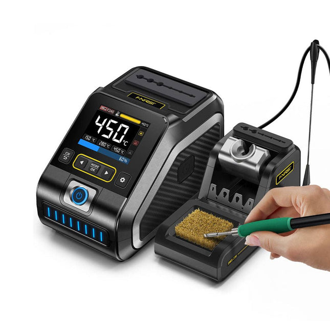
FNIRSI FNIRSI DWS-200 Intelligente Lötstation (mit F245-Lötgriff + 6 Lötspitzen)
Die FNIRSI DWS-200 ist eine leistungsstarke 200 W Smart-Lötstation, ideal für elektronische Lötanwendungen. Die Stromversorgung erfolgt über ein Schaltnetzteil, das mit einem weiten Spannungseingangsbereich von 100-240 V problemlos arbeitet. Die Station bietet einen einstellbaren Temperaturbereich von 100°C bis 450°C und ermöglicht einen einfachen Wechsel zwischen °C und °F. Zur Steigerung der Effizienz unterstützt es bis zu drei voreingestellte Temperaturwerte und kann zur Aktivierung des Standby-Modus an einen Lötkolbenständer angeschlossen werden. Die Station verfügt außerdem über einen dynamischen Temperaturkurvenmodus zur Datenüberwachung in Echtzeit, der eine präzise und konstante Leistung bei anspruchsvollen Lötaufgaben gewährleistet. Features Maximale Ausgangsleistung von 200 W für schnelles Aufheizen Breiter adaptiver Spannungseingang von 100-240 V 2,8" HD-Farb-TFT-Display mit intelligenter Steuerung Mehrere voreingestellte Gruppen, um schnell zwischen verschiedenen Einstellungen zu wechseln Unterstützt die Lötgrifftypen F245 und F210 und bietet so Flexibilität für verschiedene Lötanwendungen Echtzeit-Schlafmodus zur Verlängerung der Lebensdauer der Lötspitze Multimodus-Echtzeitüberwachung des Leistungs- und Temperaturstatus für mehr Sicherheit und Präzision Technische Daten Spitzenleistung 200 W (maximal) Temperaturbereich 100°C~450°C Display 2,8" TFT-HD-Farbbildschirm Heizzeit 1 Sekunde Schmelzzeit 3 Sekunden Eingangsspannung 100-240 V (Wechselstrom) Eingangssicherung 3 A Lötgrifftyp F245 Abmessungen (Station) 156 x 96 x 103 mm Gewicht (Station) 475 g Lieferumfang 1x FNIRSI DWS-200 Lötstation 1x Lötgriff F245 6x Lötspitzen (B, KU, K, C2, I, JS) 1x Verbindungskabel 2x Helfende Hände 1x Stromkabel (EU) Downloads Manual Firmware V1.3
€ 176,04
-

Elektor November/December 2025 (EN)
Elektor GREEN and GOLD members can download their digital edition here. Not a member yet? Click here. Relio v1.0 - Presence Detection and Remote ControlA Matter-Enabled Smart Controller for AC Appliances Designing Better PCBsA Practical Guide for Professionals and Makers KiCad 9Top New and Updated Features Precision Picoammeter (1)With Curve Tracer Functionality Down to the pA range! Christmas Star 2025A Star Is Soldered 100 mV Continuity Tester Who’s Pushing the Boundaries of European Electronics?Companies to Watch productronica 2025: What’s New in Electronics Development and Production Automation to Tackle Reshoring Manufacturing, Tariffs and Labour Shortages Beyond Future ProofCircularity in Electronics Passive ComponentsLow-Loss Inductors Enabling High-Efficiency DC/DC Converters How Desktop Manufacturing Machines Are Democratizing PCB Production Starting Out in Electronics...Needs Power UHD Displays Driven with EaseYour Guide to Easily Put Various TFT-LCDs Into Operation Quickly Soldering in 2025Practical Soldering Tips Straight from the Workbench SimulIDEAn All-in-One Tool for Circuit Prototyping 2025: An AI OdysseyFrom Autocomplete to Colleague Wordy Christmas TreeA Festive Electronics Project with a Linguistic Twist Err-lectronicsCorrections, Updates, and Readers’ Letters Analog Pipeline DistortionA Cool Audio Effect For Guitars and Other Instruments ESP32 Audio Transceiver Board (Part 3)Stereo Transmission and Dual Radio
€ 14,90
-

Elektor Digital KiCad Like A Pro – Advanced Projects and Recipes (E-book)
Mastering PCB design with real-world projects This book builts on KiCad Like a Pro – Fundamentals and Projects and aims to help you practice your new KiCad skills by challenging you in a series of real-world projects. The projects are supported by a comprehensive set of recipes with detailed instructions on how to achieve a variety of simple and complex tasks. Design the PCBs for a solar power supply, an LED matrix array, an Arduino-powered datalogger, and a custom ESP32 board. Understand the finer details of the interactive router, how to manage KiCad project teams with Git, how to use an autorouter on 2 and 4-layer PCBs, and much more. KiCad 8 is a modern, cross-platform application suite built around schematic and design editors. This stable and mature PCB tool is a perfect fit for electronic engineers and makers. With KiCad 8, you can create PCBs of any complexity and size without the constraints associated with the commercial packages. Here are the most significant improvements and features in KiCad 8, both over and under the hood: Modern user interface, completely redesigned from earlier versions Improved and customizable electrical and design rule checkers Theme editor allowing you to fully customize the look of KiCad on your screen Ability to import projects from Eagle, CADSTART, and more An improved and tightly integrated SPICE circuit simulator Autorouting with the Freerouting plugin Filters define which elements of a layout are selectable Enhanced interactive router helps you draw single tracks and differential pairs with precision New or enhanced tools to draw tracks, measure distances, tune track lengths, etc. Enhanced tool for creating filled zones A customizable coordinate system facilitates data exchange with other CAD applications Realistic ray-tracing capable 3D viewer Differential pair routing Rich repositories of symbol, footprint, and 3D shape libraries Python scripting API for programmatic customization and extensions Improved footprint wizard for fast custom footprints
€ 39,95
Mitglieder: € 35,96
-

FNIRSI FNIRSI LC1020E Hochpräzisions-LCR-Meter
Das FNIRSI LC1020E Hochpräzisions-LCR-Meter mit ESR-Tester ist eine tragbare und intelligente Lösung zum Testen elektronischer Bauteile und bietet eine Grundgenauigkeit von bis zu 0,3%. Es eignet sich ideal für Ingenieure, Techniker und Maker. Das Gerät unterstützt L/Q-, C/D- und R/D-Messungen unter Verwendung von seriellen und parallelen Ersatzschaltbildmodellen und verfügt über ein 2,8-Zoll-TFT-Farbdisplay. Mit voreingestellten Schwellenwerten und audiovisuellen Warnmeldungen ermöglicht es eine schnelle Pass/Fail-Bewertung und eignet sich somit perfekt für Serientests und die Qualitätskontrolle. Da es Testfrequenzen bis zu 100 kHz unterstützt, ist es gut für die Hochfrequenzanalyse von Induktivitäten, Kondensatoren und Widerständen geeignet. Features Genauigkeit von ±0,05% bei einer Auflösung von 4,5 Stellen Automatische R/L/C-Erkennung für schnelle Messungen 5 Prüf-Frequenzen (100 Hz–100 kHz) und 3 Spannungspegel (0,1–0,6 V) Doppelte Anzeige: L/C/R/Z + X/D/Q/θ/ESR Sortiermodus & Vorspannung für Serienprüfungen Zwei Anschlüsse (3-/5-polig) mit 4-Leiter-Kelvin-Unterstützung Datenhaltefunktion und Protokollierung für einen effizienten Arbeitsablauf Kompakt, wiederaufladbar (3000 mAh) – ideal für den Einsatz im Labor und vor Ort Technische Daten Allgemeines Prüffrequenz 100 Hz, 120 Hz, 1 kHz, 10 kHz, 100 kHz Grundgenauigkeit 0,3% Display 2,8 Zoll TFT-LCD-Display Anzeigestellen Hauptparameter: 4,5 Stellen Nebenparameter: 4,5 Stellen Messparameter Hauptparameter: AUTO/R/C/L/Z Sekundärparameter: X/D/Q/θ/ESR Messbereich L: 0–100 H C: 0–100 mF R: 0–10 M Interne Vorspannung 0,0 V, 0,5 V Prüfspannung 0,1 V, 0,3 V, 0,6 V Kalibrierungsfunktionen Leerlaufkalibrierung, Kurzschlusskalibrierung Vergleichsfunktion Dient zur Berechnung des relativen Fehlers zwischen dem Messwert des Bauteils und dem Nennwert, wird als Prozentsatz angezeigt und liefert Filterergebnisse, Nennwerte und Toleranz können eingestellt werden, wobei der Toleranzbereich von 0,1% bis 99,9% einstellbar ist Funktionsprotokoll Prüft, ob die gemessenen Bauteildaten den eingestellten Nennwert und die Toleranz erfüllen, und zeichnet die Anzahl der erfolgreichen und fehlgeschlagenen Messungen auf Konfiguration der Testanschlüsse Dreipolig, Fünfpolig Ausgangsimpedanz 100 Ω Schnittstelle USB-C (virtueller serieller Anschluss) Sonstiges Spracheinstellungen, Bildschirmhelligkeit, Toneinstellungen, Automatische Abschaltung, Kalibrierungseinstellungen, Systeminformationen Akku 3000 mAh Lithium-Akku Abmessungen 18,5 x 8,5 x 3,5 cm Gewicht 680 g Kapazität (C) Bereich: 1mF-100mF 100 Hz: 5% ±5 digits 1 kHz: 3% ±5 digits 10 kHz: / 100 kHz: / Bereich: 1uF-1mF 100 Hz: 1% ±4 digits 1 kHz: 0,5% ±5 digits 10 kHz: 2% ±5 digits 100 kHz: 3% ±4 digits Bereich: 1nF-1uF 100 Hz: / 1 kHz: 0,3% ±2 digits 10 kHz: 0,4% ±2 digits 100 kHz: 1% ±4 digits Bereich: 1pF-1nF 100 Hz: / 1 kHz: 2% ±2 digits 10 kHz: 1,5% ±2 digits 100 kHz: 2% ±4 digits Induktivität (L) Bereich: 1H-100H 100 Hz: 2% ±5 digits 1 kHz: 2% ±5 digits 10 kHz: / 100 kHz: / Bereich: 1mH-1H 100 Hz: 0,4% ±5 digits 1 kHz: 0,3% ±2 digits 10 kHz: 0,4% ±3 digits 100 kHz: 2,5% ±5 digits Bereich: 10uH-1mH 100 Hz: 3% ±5 digits 1 kHz: 0,5% ±4 digits 10 kHz: 0,5% ±3 digits 100 kHz: 1,5% ±5 digits Bereich: 1uH-10uH 100 Hz: / 1 kHz: 2% ±5 digits 10 kHz: 2% ±5 digits 100 kHz: 4% ±5 digits Widerstand (R) Bereich: 1MΩ-10MΩ 100 Hz: 5% ±4 digits 1 kHz: 3% ±3 digits 10 kHz: / 100 kHz: / Bereich: 1KΩ-1MΩ 100 Hz: 0,4% ±4 digits 1 kHz: 0,2% ±2 digits 10 kHz: 0,3% ±3 digits 100 kHz: 0,6% ±5 digits Bereich: 1Ω-1KΩ 100 Hz: 1,5% ±4 digits 1 kHz: 0,3% ±2 digits 10 kHz: 0,3% ±3 digits 100 kHz: 0,6% ±5 digits Bereich: 10mΩ-1Ω 100 Hz: 4% ±4 digits 1 kHz: 2% ±5 digits 10 kHz: 2% ±5 digits 100 kHz: 5% ±5 digits Lieferumfang 1x FNIRSI LC1020E LCR-Messgerät 1x Kelvin-Messklemme 2x Messleitungen (1x schwarz, 1x rot) 1x Kurzschlussplatte 1x USB-C Kabel 1x Manual Downloads Manual Firmware V1.1
€ 84,95€ 69,95Bestpreis
-
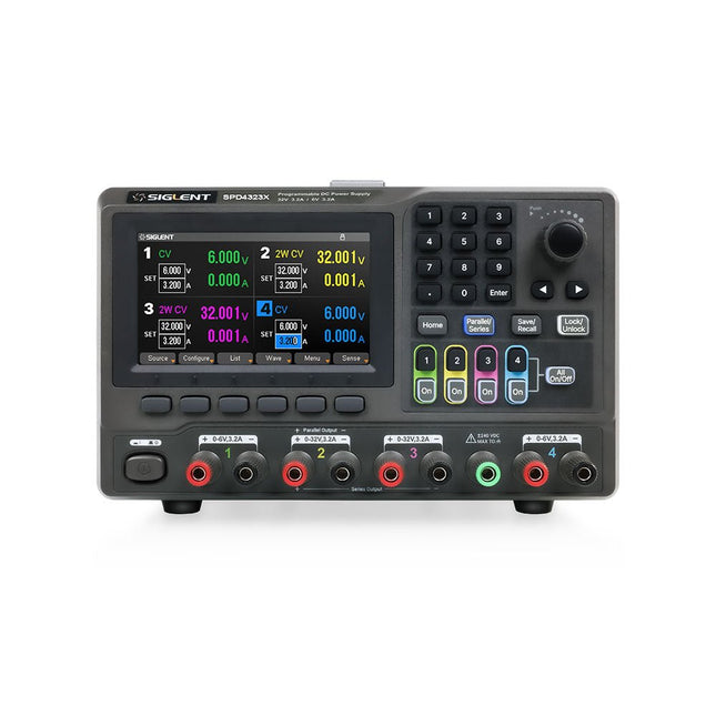
Siglent Siglent SPD4323X 4-Kanal Netzteil (240 W)
The Siglent SPD4323X is a 4-channel DC Linear Programmable Power Supply equipped with a 4.3-inch TFT-LCD display, friendly human-machine interface, and excellent performance indicators. Real-time waveform display provides engineers with an informative user interface. SPD4323X offers a total output power of 240 W with a resolution of 1 mV/1 mA. The maximum voltage and current for each channel are as follows: CH1: 6 V/3.2 A CH2: 32 V/3.2 A CH3: 32 V/3.2 A CH4: 6 V/3.2 A Features Rated output power: 240 W Rated voltage: 32 V, 12 V, 30 V Up to four high-precision power supplies with independent controllable outputs, supporting CH2 and CH3 series and parallel connections Clear graphical interface with waveform and timer display modes 5-digit voltage and current display with minimum resolution of 1 mV, 1 mA Fast output response time: <50us The high current channel support remote voltage compensation sense function. The maximum compensation voltage is 0.6 V Overvoltage protection and overcurrent protection or safe and accurate operation Equipped with a 4.3-inch TFT-LCD display (480 x 272 resolution) USB and LAN standard communication USB-GPIB module is optional Excellent channel density with up to 4 channels in a 3U half rack package Internal data storage for setups and parameters Embedded Web Server with instrument communication that doesn’t require software installation Fully SCPI programming command set support as well as a LabView driver for remote control and system automation Technische Daten SPD4323X SPD4121X SPD4306X Channel Output CH1: Voltage 0 to 6 V Current 0 to 3.2 ACH2: Voltage 0 to 32 V Current 0 to 3.2 ACH3: Voltage 0 to 32 V Current 0 to 3.2 ACH4: Voltage 0 to 6 V Current 0 to 3.2 A CH1: Voltage 0 to 15 V Current 0 to 1.5 ACH2: Voltage 0 to 12 V Current 0 to 10 ACH3: Voltage 0 to 12 V Current 0 to 10 ACH4: Voltage 0 to 15 V Current 0 to 1.5 A CH1: Voltage 0 to 15 V Current 0 to 1.5 ACH2: Voltage 0 to 30 V Current 0 to 6 ACH3: Voltage 0 to 30 V Current 0 to 6 ACH4: Voltage 0 to 15 V Current 0 to 1 A Resolution 1 mV, 1 mA 1 mV, 1 mA 1 mV, 1 mA Setting Accuracy Voltage: ±(0.03% of reading+10) mV, Current: ±(0.3% of reading+10) mA Voltage: ±(0.03% of reading+10) mV, Current: ±(0.3% of reading+10) mA Voltage: ±(0.03% of reading+10) mV, Current: ±(0.3% of reading+10) mA Readback Accuracy Voltage: ±(0.03% of reading+10) mV, Current: ±(0.3% of reading+10) mA Voltage: ±(0.03% of reading+10) mV, Current: ±(0.3% of reading+10) mA Voltage: ±(0.03% of reading+10) mV, Current: ±(0.3% of reading+10) mA Display 4.3" TFT-LCD 5-digit voltage and current display 4.3" TFT-LCD 5-digit voltage and current display 4.3" TFT-LCD 5-digit voltage and current display Output power 240 W 285 W 400 W Lieferumfang 1x Siglent SPD4323X Power Supply 1x Power cord (EU) 1x Output test cord (3 A) 1x USB cable 1x Quick start guide Downloads Datasheet Manual Quick start
€ 762,30
Bestpreis
-
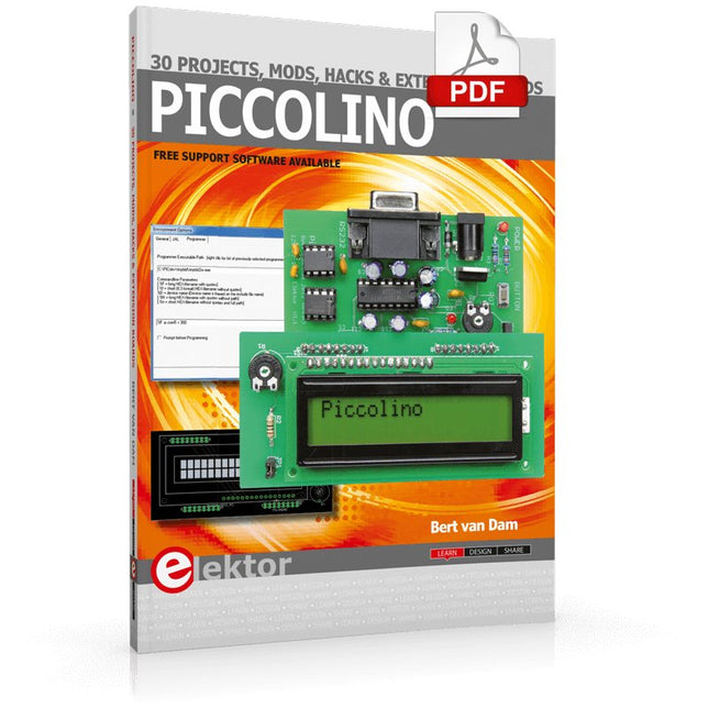
Elektor Digital Piccolino - 30 Projects, mods, hacks and extension (E-book)
The Piccolino rapid development board can be used to design microcontroller circuits quickly. The Piccolino has a fast 16f887 PIC microcontroller, voltage regulator, and communications module, and can be easily extended using its four headers. This e-book contains 30 projects based on the Piccolino. We'll use its unique communications facilities and get the Piccolino to communicate with programs on a PC. On the PC, we use the free programming language Small Basic. You can use this to create Windows programs with buttons and graphs quickly. You will learn how to analyze components such as inductors, capacitors, and OPAMPs, and how to display the measurement results in a graphical format. This will help you to design your circuits easily. We will then start to adapt to the Piccolino. We'll add components to it to make it more powerful, with extra features such as flow control and digital to analog conversion. The clear instructions will enable you to design and build your adaptations. This way you can make your custom designed Piccolino. We'll end up making an extension: a PCB that that can be mounted on the Piccolino headers. As an example, we'll design and build an extension for an LCD. You can use the included board layout to make your PCB or have it made for you. At the same time, you will learn how to make your extensions. The only limitation is your imagination! The clear descriptions along with circuit diagrams and photos, will make the building of these projects an enjoyable experience. Each project has a clear explanation of the reasons why it was designed in a particular way. This helps you learn a lot about the Piccolino, as well as Small Basic, and the components that are used in this e-book. You can adapt the projects to suit your requirements or combine several projects.
€ 34,95
Mitglieder: € 31,46
-

Elektor Labs Elektor Rauscharmes Labornetzteil
Das rauscharme Labornetzteil von Elektor ist ein vollständig analoges, einstellbares, symmetrisches Gerät mittlerer Leistung, das ohne Schalt- oder digitale Komponenten auskommt. Es bietet eine Ausgangsspannung, die zwischen 0 V und ±22 V einstellbar ist, sowie einen Ausgangsstrom, der von 0 A bis 1 A eingestellt werden kann. Da auf jegliche Art von Schalttechnik verzichtet wird, liefert das Design extrem geringes Rauschen. Zur Anzeige beider Ausgangsspannungen und -ströme werden vier kleine analoge Einbauinstrumente mit Drehspulmesswerk verwendet. Die meisten modernen Labornetzgeräte und AC-Adapter arbeiten mit Schaltnetzteiltechnik. Selbst die besten Ausführungen weisen zwangsläufig hochfrequente Restwelligkeit und andere Schaltartefakte am Ausgang auf, die die Prüfung empfindlicher analoger Schaltungen stören und Messungen kleiner Signale beeinträchtigen können. Um dieses Problem zu vermeiden, setzt dieses Konzept auf ein vollständig analoges Netzgerät. Obwohl es weniger effizient ist als vergleichbare Schaltnetzteile, spielt die geringere Effizienz beim Einsatz auf dem Prüfstand kaum eine Rolle und sorgt für sauberere und zuverlässigere Messergebnisse. Da viele analoge Schaltungen eine symmetrische Versorgung benötigen, liefert dieses Design positive und negative Ausgangsspannungen gleicher Höhe. Eine geringfügige Nachjustierung ist möglich, um eventuelle Ungleichgewichte auszugleichen. Selbstverständlich ist auch eine einstellbare Strombegrenzung integriert. Das Kit enthält die für den Aufbau des Netzteils erforderlichen Komponenten, mit Ausnahme der Transformatoren. Technische Daten Ausgangsspannung 0…+22 V, 0, −22 V Ausgangsstrom 0…+1 A, 0…−1 A Rauschen −85 dBV (bei 0,95 A/20 V, B = 22 kHz) −84 dBV (bei 0,95 A/20 V, B > 500 kHz) Restwelligkeit 50 µVRMS (bei 950 mA/20 V, B = 22 kHz, hauptsächlich 100-Hz-Anteil) Lieferumfang 3x Platinen: Regler (PCB-1), Netzfilter (PCB-2) und Transformator (PCB-3) Alle Bauteile mit Ausnahme der Netztransformatoren 4x Drehspulmesswerke Zusätzliche Teile für die Verdrahtung (Drähte, Bananenbuchsen, Kaltgeräte-Netzmodul usw.) Nicht enthalten Die drei Netztransformatoren Ein Gehäuse Stückliste Für die Spannungsregler-Platine (240386-1) Widerstände (250 mW, 1%) R1 = 12 Ω R2, R8, R37, R62 = 1 MΩ R3, R7, R10, R13, R17, R20, R22, R30, R35, R42, R45, R47, R55, R60 = 100 Ω, 600 mW R4, R5 = 4.7 kΩ R6 = 100 kΩ R9, R12, R14, R36, R38, R39, R61, R63, R66, R72, R78, R79 = 10.0 kΩ, 600 mW R11 = 9.76 kΩ, 600 mW R15, R40 = 44.2 kΩ, 600 mW R16, R41, R77 = 1 kΩ R18, R43 = 1.5 kΩ, 1 W, 5% R19, R44 = 470 Ω, 1 W, 5% R21, R46 = 330 Ω, 600 mW R23, R24, R48, R49 = 1.0 Ω, 1 W R25, R50 = 1 kΩ, 1 W, 5% R26, R28, R51, R53 = 1.000 kΩ 0.1%, 15 ppm/C R27, R29, R52, R54 = 10.00 kΩ 0.1%, 15 ppm/C R31, R56 = 1.2 kΩ, 1 W, 5% R32, R57 = 47 kΩ R33, R58 = 270 Ω R34, R59 = 27 kΩ R64, R69 = 12.0 kΩ R65 = 3.0 kΩ, 600 mW R67, R80 = 470 Ω, 600 mW R68, R70 = 6.8 kΩ, 600 mW R71 = 30.0 kΩ,, 600 mW R73, R74, R75, R76 = 10 MΩ P1, P2, P3 = 10 kΩ, 200 mW, 20%, potentiometer, 1 turns, single, lin., panel mount P4, P5 = 500 Ω, 500 mW, 10%, trimmer, 25 turns, 3296Y-1-501LF Bourns P6, P7 = 10 kΩ, 500 mW, 10%, trimmer, 25 turns, 3296Y-1-501LF Bourns Kondensatoren C1 = 100 nF, 50 V, 10%, ceramic X7R, LS 5 mm C2, C3, C6, C7, C30 = 10 µF, 63V, 20%, LS 2.5 mm, 3000hours@105°C C4, C5, C8, C9, C13, C14, C18, C19, C23, C24, C28, C29, C31, C32, C38, C39 = 100 nF, 250 V, 10%, PET, LS 7.5 mm C10, C20 = 47 nF, 100 V, 5%, PET, LS 5 mm C11, C21 = 10 nF, 100 V, 5%, PET, LS 5 mm C12, C22 = 220 µF, 35 V, 20%, 0.024 Ω, LS2.5/3.5 mm, Ir 3.4 A, 2000hours@125°C, polymer C15, C25 = 120 µF, 50 V, 20%, ESR 0.02 Ω, Diam. 10 mm max., LS 5 mm C16, C26 = 15 nF, 100 V, 5%, PET, LS 5 mm C17, C27 = 47 nF, 100 V, 5%, PET, LS 5 mm C33, C34 = 22 µF, 50 V, 20%, LS 2 mm, 10000 hours @ 105°C C35, C36, C44, C45 = 1 µF, 100 V, 10%, LS 5 mm, ceramic X7R C37 = 100 uF, 50 V, 20%. LS 3.5 mm C40, C41, C42, C43, C46, C47, C48, C49 = 1000 µF, 50 V, 20%, LS 5/7.5 mm, Ir 3.32 A, 10000hours@105°C, D 16 mm C50, C51, C52, C53 = 47 nF, 100 V, 10%, ceramic X7R, LS 5 mm Induktivitäten L1, L2 = 4.7 µH, 3.2 A, 0.033 Ω, LS 5 mm, RLB0914-4R7ML Bourns L3 = Commom mode choke, 14.5 mH, 3 A, SSRH24NH-30145 Kemet Halbleiter D1, D2, D3, D4, D5, D9, D10, D11, D15 = BAT85, DO-34 D6, D7, D12, D13 = SR560, DO-201AD D8, D14, D16 = 1N4148, DO-35 D17 = Zenerdiode, 5.6 V, 0.5 W, DO-41 D18, D19 = 1N4004, DO-41 D20, D21 D22, D23 = V30100CI-M3/P, dual common cathode, TO-220 D24 = Zener diode, 30 V, 1 W, DO-41 LED1, LED2 = LED, red, T-1 (3 mm) LED3, LED4 = LED, green, T-1 (3 mm) TVS1, TVS2 = BZW50-33B, R6 T1, T2, T4 = BC337.25, TO-92 T3 = NJW0302G, TO-3P T5, T6, T8 = BC327.25, TO-92 T7 = NJW0281G, TO-3P T9 = BD139, TO-126 (SOT-32) IC1 = LM334Z, TO-92 IC2 = LM4040AIZ-5.0/NOPB, TO-92 (TO-226AA-3) IC3, IC4 = OPA2992IDR, SOIC-8 IC5, IC6 = OPA4992IDR, SOIC-14 IC7 = OPA992IDBVR, SOT-23-5 IC8 = LM339N, DIP-14 IC9 = LM317, TO-220 IC10 = LM337, TO-220 Sonstiges F1, F2 = 5×20 mm fuse, 1.6 A, fast acting HS1, HS2 = Heatsink MC33271 (for T3/T7), 2.7°C/W, PCB mount, height 63.5 mm K1, K4 = 3-way screw terminal block, LS 3.5 mm, max. 1.5 mm² K2, K3 = 3-way screw terminal block, LS 3.5 mm, max. 1 mm² M1, M3 = Moving coil meter, Range 30 V, type 91C4, 45×45 mm M2, M4 = Moving coil meter, Range 1 A, type 91C4, 45×45 mm² RE1 = Relay DPDT,5V, UA2-5NU Verschiedenes 3× 3-way screw terminal block, LS 3.5 mm, max. 1 mm² (for P1, P2, P3) 4× Pin header, 1×2, vertical, pitch 2.54 mm (for LED1, LED2, LED3, LED4) 4× Pin socket, 1×2, vertical. pitch 2.54 mm (for LED1, LED2, LED3, LED4) 2× Heatsink FK222SA220, 20°C/W, PCB mount (for IC9 & IC10) 2× Mica thermal pad for TO-220, 12×18×0.05 mm (for IC9 & IC10) 2× Insulating bushing IB 6, TO-220 (for IC9 & IC10) 2× Ceramic thermal pad, 23×20×2 mm (for T3 & T7) 2× PCB Fuse Holder, for 5×20 mm fuse, 10 A (for F1, F2) 2× Cover for PCB Fuse Holder, transparent (for F1, F2) 2× 2-way screw terminal block, LS 3.5 mm, max. 1 mm² (for M1 & M3) 2× 2-way screw terminal block, LS 3.5 mm, max. 1.5 mm² (for M2 & M4) 8× M3 solder lug, thickness 0.35 mm (for M1…M4) M4 solder lug, thickness 0.35 mm (to connect 4 mm banana connectors) Screened cable, 1 pair, 2×24 AWG/0.22 mm², 1 m (for P1, P2 & P3) IC socket, DIP, 14 contacts (for IC8) M3 washer, plain, steel M3 screw, 16 mm, steel, pan head M3 nut M3 spring washer 50 mm M3 standoff, steel, male-female 12 mm M3 standoff, steel, male-female 10 mm M3 standoff, steel, male-female M3 screw, 8 mm, steel, pan head Für die Netzfilter-Platine (240386-2) Widerstand R1 = 220 kΩ, 1 W, 500 V, 5% Kondensatoren C1, C2 = 470 nF, 305 VAC, Class X2, 11 × 27 mm max., LS 15/22.5 mm C3, C4, C5, C6 = 2.2 nF, 300 VAC, Class Y2, 13 × 4 mm, LS 10 mm, PP Induktivitäten L1, L2 = Common-mode choke, 6.8 mH, 1.7 A, TDK B82732R2172B030 Halbleiter MOV1 = TVS varistor, 300 VAC, S14K300 (230 VAC, B72214S0301K101) and SK14K150 (150 VAC, B72214S0151K101) Sonstiges K1, K2 = 3-way screw terminal block, LS 7.62 mm F1 = Time-delay fuse, 0.5 A (230 VAC) or 1 A (115 VAC) Verschiedenes 1× Fuse holder, 5×20 mm, 10 A, 500 VAC 1× Transparent fuse cover 4× 10 mm M3 standoff, steel, male–female 4× M3 screw, 8 mm, steel, pan head 4× M3 nut Für die Transformator-Platine (240386-3) Widerstände R1, R2 = 2.7 kΩ, 600 mW, 1% R3 = 10.0 kΩ, 600 mW, 1% Kondensator C1 = 220 µF, 50 V, 20%, Ø10 mm, LS 5 mm, 4000 h @ 105°C Transformatoren (nicht im Lieferumfang dieses Kits enthalten!) TR1, TR2, TR3 = 2×7 V, 25 VA, PCB-mounted toroid, 70060K Talema Halbleiter D1–D4 = 1N4148, DO-35 D5, D6 = 1N4004, DO-41 D7 = Zener 5.6 V, 1.3 W, DO-41 LED1 = LED, red, T-1 (3 mm) IC1, IC2 = MOC8021M, CTR ≥ 1000%, DIP-6 Sonstiges F1, F2, F3 = 160 mA time-delay fuse (230 VAC) or 315 mA time-delay fuse (115 VAC) K1 = 2-way screw terminal block, LS 7.62 mm K2 = 3-way screw terminal block, LS 3.5 mm, max 1.5 mm² K3, K4 = 3-way screw terminal block, LS 3.5 mm, max 1 mm² RE1, RE2 = Relay DPDT, 5 A/250 VAC / 24 VDC Verschiedenes 1× Pin header 1×2, pitch 2.54 mm + matching socket for LED1 3× Fuse holder 5 × 20 mm, 10 A, 500 VAC + transparent cover 3× M4 screw, 8 mm, pan head + washer for TR1-TR3 8× M3 screw, 8 mm, pan head + nut + washer 8× 10 mm M3 standoff, steel, male–female 2× IC socket, DIP-6 for IC1 & IC2 Weitere Bauteile 1 m red insulated wire, stranded, 1.5 mm² 0.5 m blue insulated wire, stranded, 1.5 mm² 0.5 m black insulated wire, stranded, 1.5 mm², 0.5 m 2 m red insulated wire, stranded, D 0.56 mm (0.25 mm²) 2 m black insulated wire, stranded, D 0.56 mm (0.25 mm²) 0.5 m Multicore Cable, Flexible, 3 Core, 0.75 mm² (24 x 0.2 mm) Red banana socket Black banana socket Blue banana socket Green banana socket IEC Power Entry Module with switch, IEC C14 3 crimp terminals, FASTON, 4.75 x 0.81 mm 3 knobs Links Elektor Labs JumpStarter Page Artikel (Teil 1) Artikel (Teil 2)
€ 299,00€ 249,00Bestpreis
-

Quick Quick 861DW Heißluft-Rework-Station (1000 W)
Der Quick 861DW ist eine fortschrittliche Heißluft-Rework-Station mit einer Heizleistung von 1000 W. Es ist für das professionelle Löten elektronischer SMD-Bauteile mit bleifreien Loten konzipiert. Features Drei programmierbare Kanäle CH1, CH2 und CH3 (für Luftvolumen- und Temperaturparameter). Passwortschutz und Tastensperrfunktion verfügbar. Der Magnetschalter in einem Ständer kann die Station automatisch in den Ruhemodus versetzen, wenn sie nicht verwendet wird. Einfache Echtzeitbedienung, automatische Schlaffunktion verfügbar, Parameter können im Schlafmodus eingestellt werden. Closed-Loop-Sensor, Temperaturregelung durch Mikrocomputer-Nullauslöser, große Leistung, schneller Temperaturanstieg, Temperatur kann einfach und genau eingestellt werden, wird nicht durch den Luftstrom beeinflusst. Bürstenloser Wirbelventilator, großer Luftstrombereich einstellbar, für viele Anwendungen geeignet. Automatische Kühlfunktion verfügbar, Keramikheizung mit langer Lebensdauer. Technische Daten Leistung 1000 W Betriebsspannung Wechselstrom 200-240 V Temperaturbereich 100-500°C Luftmenge Klasse 1-120 Luftstrom 50 l/min (max.) Abmessungen 188 x 245 x 135 mm Gewicht 3,65 kg Downloads Manual
€ 251,50
-

Elektor Publishing Develop your own Bluetooth Low Energy Applications
For Raspberry Pi, ESP32 and nRF52 with Python, Arduino and Zephyr Bluetooth Low Energy (BLE) radio chips are ubiquitous from Raspberry Pi to light bulbs. BLE is an elaborate technology with a comprehensive specification, but the basics are quite accessible. A progressive and systematic approach will lead you far in mastering this wireless communication technique, which is essential for working in low power scenarios. In this book, you’ll learn how to: Discover BLE devices in the neighborhood by listening to their advertisements. Create your own BLE devices advertising data. Connect to BLE devices such as heart rate monitors and proximity reporters. Create secure connections to BLE devices with encryption and authentication. Understand BLE service and profile specifications and implement them. Reverse engineer a BLE device with a proprietary implementation and control it with your own software. Make your BLE devices use as little power as possible. This book shows you the ropes of BLE programming with Python and the Bleak library on a Raspberry Pi or PC, with C++ and NimBLE-Arduino on Espressif’s ESP32 development boards, and with C on one of the development boards supported by the Zephyr real-time operating system, such as Nordic Semiconductor's nRF52 boards. Starting with a very little amount of theory, you’ll develop code right from the beginning. After you’ve completed this book, you’ll know enough to create your own BLE applications.
€ 39,95
Mitglieder: € 35,96
-

Elektor Publishing Professional SMD Assembly
Practical Low-Cost Methods for Reliable PCB Production This book explains how to carry out reliable SMD assembly using affordable tools and small-scale equipment. It follows the complete workflow step by step, including tool selection, solder paste handling, stencil use, component placement, reflow methods, inspection, and rework. The focus is on bench-level and small-lab production rather than industrial assembly lines. It shows practical methods for building single and double-sided SMD boards with repeatable results. Topics include solder paste and flux, temperature profiles, hot air and hotplate techniques, small reflow ovens, inspection methods, and defect correction. Checklists and example workflows are included to help reduce errors and improve consistency. Key features: Tools and supplies for SMD assembly and rework Solder paste types, storage, and handling Stencils and paste application methods Pick and place workflow and component orientation Temperature profiles and reflow methods Hot air, hotplate, and reflow oven processes Inspection and quality control Common defects such as tombstoning and solder bridges Practical rework and component replacement Bench-level professional workflows and checklists This book is designed as a practical bench reference for anyone who wants to assemble and troubleshoot their own SMD boards with reliable results.
€ 24,95
Mitglieder: € 22,46
-

FNIRSI FNIRSI DPS150PD DC-Netzteil (150 W)
Das FNIRSI DPS150 ist ein leistungsstarkes, einstellbares Gleichstromnetzteil, das über eine USB-C-Eingangsschnittstelle und mehrere Stromversorgungsmodi verfügt und eine präzise Einstellung der Ausgangsspannung (0-30 V) und des Ausgangsstroms (0-5 A) ermöglicht. Es bietet einen effizienten, verbrauchsarmen und stabilen Ausgang und ist mit mehreren Sicherheitsschutzfunktionen ausgestattet, darunter Überspannung, Überstrom, Überlastung, Überhitzung und Verpolung. Es kann flexibel für die serielle Verbindung mehrerer Geräte eingesetzt werden, verfügt über eine umfangreiche und benutzerfreundliche Anzeige und Bedienung sowie ein kompaktes und tragbares Design und erfüllt verschiedene Anwendungsanforderungen. Features 30 V, 5 A, 150 W variabler Gleichstrom mit 0,01 V, 0,001 A Präzision, CC/CV-Modi und <20 mV Welligkeit zum Schutz empfindlicher Elektronik. Unterstützt PC-, QC- und DC-Eingänge mit programmierbaren Ausgängen und 6 voreingestellten Spannungs-/Stromeinstellungen. Kompatibel mit 4 mm-Bananensteckern, U-förmigen Anschlüssen und Kupferdrähten für verschiedene Geräte. 8 Sicherheitsmechanismen, einschließlich Überspannungs-, Strom-, Kurzschluss- und Überhitzungsschutz. 2,8" HD-IPS-Bildschirm mit um 90° umklappbarer, numerischer und Kurvenanzeige für einfache Überwachung. Kleines, platzsparendes Design für den Einsatz in Laboren, Reparaturen und Heimwerkerprojekten. Technische Daten Eingangsspannung 5~32 V DC Eingangsstrom 100 mA-5 A Ausgangsspannung 0-30 V Ausgangsstrom 0~5 A Ausgangsleistung 0-150 W Eingabeweg PD-Schnellladegerät QC-Schnellladegerät Powerbank Gleichstromadapter Betriebsumgebung 0-40°C Regulierung laden 0,49% Volllasteffizienz 96,30% Display 2,8 Zoll (320 x 240) Abmessungen 106 x 76 x 28 mm Gewicht 178 g Lieferumfang 1x DPS150 Netzteil 2x Krokodilklemmendrähte (schwarz und rot) 1x C2C PD Ladekabel 1x 100 W PD GaN Adapter (EU) 1x Micro-USB-Kabel 1x Manual Downloads Manual Firmware V0.0.1
€ 93,43


