
Suchergebnisse für "rgb OR digit OR clock OR 160100 OR 91"
-
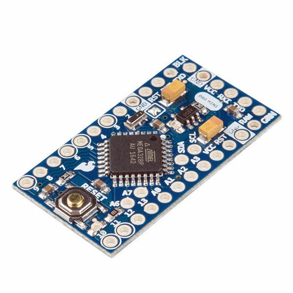
SparkFun SparkFun Arduino Pro Mini 328 (5 V, 16 MHz)
Der Arduino Pro Mini ist ein Mikrocontroller-Board auf Basis des ATmega328P. Es hat 14 digitale Eingangs-/Ausgangs-Pins (von denen 6 als PWM-Ausgänge verwendet werden können), 6 analoge Eingänge, einen On-Board-Resonator, eine Reset-Taste und Löcher für die Montage von Stiftleisten. Eine sechspolige Stiftleiste kann mit einem FTDI-Kabel oder einem SparkFun-Breakout-Board verbunden werden, um die Platine über USB mit Strom zu versorgen und mit ihr zu kommunizieren. Der Arduino Pro Mini ist für die semi-permanente Installation in Objekten oder Ausstellungen gedacht. Die Platine wird ohne vormontierte Stiftleisten geliefert, was die Verwendung verschiedener Arten von Steckern oder das direkte Anlöten von Drähten ermöglicht. Das Pin-Layout ist mit dem Arduino Mini kompatibel. Technische Daten Microcontroller ATmega328P Board Stromversorgung 5-12 V Schaltung Betriebsspannung 5 V Digitale E/A-Pins 14 PWM Pins 6 UART 1 SPI 1 I²C 1 Analogeingangs-Pins 6 Externe Interrupts 2 DC-Strom pro I/O-Pin 40 mA Flash Memory 32 KB, davon 2 KB vom Bootloader verwendet SRAM 2 KB EEPROM 1 KB Taktgeschwindigkeit 16 MHz Abmessungen 18 x 33.3 mm Downloads Eagle files Schematics
€ 14,95€ 9,95Bestpreis
-

SunFounder Universal Maker Sensor Kit (für Raspberry Pi, Pico W, Arduino, ESP32)
Entdecken Sie grenzenlose Kreativität mit dem Universal Maker Sensor Kit, das für Raspberry Pi, Pico W, Arduino und ESP32 entwickelt wurde. Dieses vielseitige Kit ist mit gängigen Entwicklungsplattformen kompatibel, darunter Arduino Uno R4 Minima/WiFi, Uno R3, Mega 2560, Raspberry Pi 5, 4, 3B+, 3B, Zero, Pico W und ESP32. Mit über 35 Sensoren, Aktoren und Displays eignet es sich perfekt für Projekte von Umweltüberwachung und Smart-Home-Automatisierung bis hin zu Robotik und interaktivem Gaming. Schritt-für-Schritt-Tutorials in C/C++, Python und MicroPython führen Anfänger und erfahrene Maker gleichermaßen durch 169 spannende Projekte. Features Umfassende Kompatibilität: Vollständige Unterstützung für Arduino (Uno R3, Uno R4 Minima/WiFi, Mega 2560), Raspberry Pi (5, 4, 3B+, 3B, Zero, Pico W) und ESP32. Dies ermöglicht umfassende Flexibilität auf zahlreichen Entwicklungsplattformen. Enthält Anleitungen für 169 Projekte. Umfassende Komponenten: Mehr als 35 Sensoren, Aktoren und Anzeigemodule für vielfältige Projekte wie Umweltüberwachung, Smart Home-Automatisierung, Robotik und interaktive Spielesteuerungen. Ausführliche Tutorials: Klare Schritt-für-Schritt-Anleitungen für Arduino, Raspberry Pi, Pico W, ESP32 und alle enthaltenen Komponenten. Es stehen Tutorials in C/C++, Python und MicroPython zur Verfügung, die sowohl für Anfänger als auch für erfahrene Maker geeignet sind. Für alle Kenntnisstufen geeignet: Bietet strukturierte Projekte, die Benutzer nahtlos vom Anfänger zum Fortgeschrittenen in Elektronik und Programmierung führen und so Kreativität und technisches Know-how fördern. Lieferumfang Breadboard Tastenmodul Kapazitives Bodenfeuchtemodul Flammensensormodul Gas-/Rauchsensormodul (MQ2) Gyroskop & Beschleunigungssensormodul (MPU6050) Hall-Sensormodul Infrarot-Geschwindigkeitssensormodul IR-Hindernisvermeidungssensormodul Joystickmodul PCF8591 ADC/DAC-Wandlermodul Fotowiderstandsmodul PIR-Bewegungssensormodul (HC-SR501) Potentiometermodul Pulsoximeter- und Herzfrequenzsensormodul (MAX30102) Regentropfenerkennungsmodul Echtzeituhrmodul (DS1302) Drehgebermodul Temperatursensormodul (DS18B20) Temperatur- und Feuchtigkeitssensormodul (DHT11) Temperatur, Luftfeuchtigkeit und Drucksensor (BMP280) Time-of-Flight-Mikro-LIDAR-Distanzsensor (VL53L0X) Berührungssensormodul Ultraschallsensormodul (HC-SR04) Vibrationssensormodul (SW-420) Wasserstandssensormodul I²C LCD 1602 OLED-Displaymodul (SSD1306) RGB-LED-Modul Ampelmodul 5-V-Relaismodul Kreiselpumpe L9110-Motortreibermodul Passives Summermodul Servomotor (SG90) TT-Motor ESP8266 Modul JDY-31 Bluetooth-Modul Stromversorgungsmodul Dokumentation Online-Tutorial
€ 69,95
Mitglieder: € 62,96
-
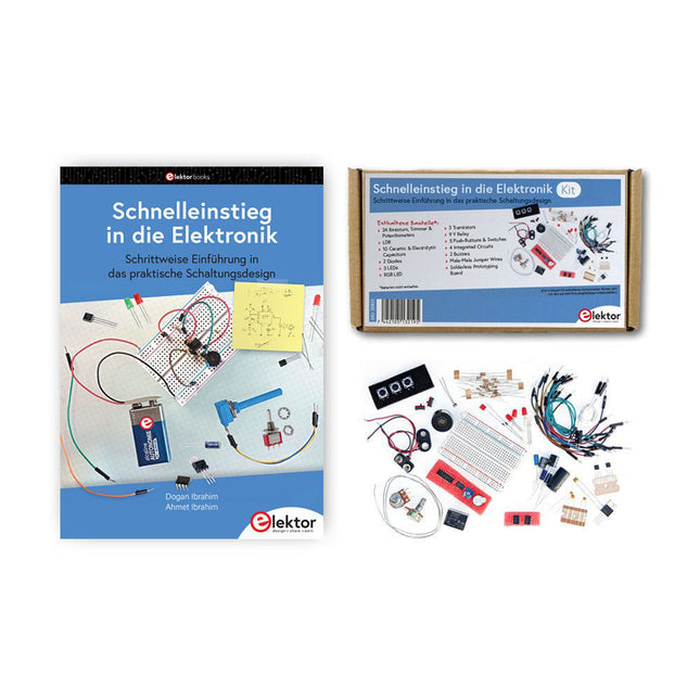
Elektor Bundles Schnelleinstieg in die Elektronik (Bundle)
Der Einstieg in die Elektronik ist einfacher, als Sie denken! Mit diesem Bundle – bestehend aus Buch und Experimentierkit – entdecken Sie die Grundlagen der Elektro- und Elektroniktechnik Schritt für Schritt. Anhand spannender Experimente lernen Sie praxisnah und verständlich, ganz ohne komplizierte Fachbegriffe oder langwierige Berechnungen. So sind Sie schon bald in der Lage, Ihre eigenen Elektronikprojekte umzusetzen! Das Kit enthält alle notwendigen Komponenten, um die meisten im Buch beschriebenen Schaltungen direkt auf dem Steckbrett aufzubauen und praktisch zu erproben. Das Kit kann selbstverständlich auch ohne das Buch zum Aufbau anderer Schaltkreise und zur Durchführung eigener Experimente verwendet werden. Inhalt des Kits 1x 39 Ω, 1 W Widerstand 1x 47 Ω Widerstand 1x 180 Ω Widerstand 1x 330 Ω Widerstand 3x 1 kΩ Widerstand 1x 2,2 kΩ Widerstand 1x 3,9 kΩ Widerstand 1x 6,8 kΩ Widerstand 1x 10 kΩ Widerstand 1x 15 kΩ Widerstand 1x 22 kΩ Widerstand 1x 33 kΩ Widerstand 1x 47 kΩ Widerstand 1x 56 kΩ Widerstand 1x 82 kΩ Widerstand 1x 120 kΩ Widerstand 1x 680 kΩ Widerstand 2x 100 kΩ Widerstand 1x 10 kΩ Trimmer 1x 10 kΩ Linearpotentiometer 1x 100 kΩ Linearpotentiometer 1x LDR 1x 1 nF Keramikkondensator 2x 10 nF Keramikkondensator 1x 100 nF Keramikkondensator 1x 1 µF, 25 V Aluminium-Elektrolytkondensator 2x 10 µF, 25 V Aluminium-Elektrolytkondensator 1x 100 µF, 25 V Aluminium-Elektrolytkondensator 1x 470 µF, 25 V Aluminium-Elektrolytkondensator 1x 1000 µF, 25 V Aluminium-Elektrolytkondensator 1x RGB-LED, Common-Cathode (CC) 1x 1N4148 Kleinsignaldiode 1x 1N4733A 5,1 V, 1 W Zenerdiode 3x LED, rot 2x BC337 NPN-Transistor 1x IRFZ44N N-Kanal-MOSFET 2x NE555-Timer 1x LM393-Komparator 1x 74HCT08 Quad-AND-Gatter 3x Tastschalter 2x SPDT-Schalter 1x Relais, SPDT, 9 VDC 1x Aktiver Summer 1x Passiver Summer 50 cm Massivdraht, 16 AWG, ohne Mantel 2x PP3 9 V Batterieclip 1x Steckbrett 20x Überbrückungskabel Dieses Bundle enthält: Buch: Schnelleinstieg in die Elektronik (Einzelpreis: 45 €) Kit: Schnelleinstieg in die Elektronik (Wert: 45 €)
€ 89,95€ 69,95Bestpreis
-

Seeed Studio Seeed Studio RF Explorer 3G Combo Spektrum-Analyzer
The Seeed Studio RF Explorer 3G Combo is a handheld digital spectrum analyzer and an affordable tool for working across a wide range of popular frequency bands. It is based on a highly integrated frequency synthesizer and a double-balanced mixer, providing high performance, compact dimensions, low power consumption, and excellent value. Designed for both indoor and outdoor use, the RF Explorer 3G Combo can also be connected to a PC via a standard Mini-USB 2.0 connector for additional functionality. This model combines a WSUB1G base unit with an RFEMWSUB3G expansion module, supplied fully assembled and tested. It features two SMA connectors and includes two antennas: a dual-band 144/430 MHz telescopic antenna for sub-GHz frequencies and a helical whip antenna for the 2.4 GHz band. Additional frequency-specific antennas may be required for optimal performance in certain supported frequency ranges. This combination provides the wide frequency coverage of the WSUB3G module together with the high sensitivity and fast response of the WSUB1G unit in the commonly used sub-1 GHz frequency range. Features Pocket size and light weight Solid aluminum metal case Includes a transport EVA carry case for RF Explorer Spectrum Analyzer mode with Peak Max and Hold, Normal, Overwrite and Averaging modes Lifetime free firmware upgrades available, open to community requested features High capacity Lipo for 16+ hours of continuous run, rechargeable by USB Windows PC client Open Source Can be extended with internal Expansion Modules for additional band and functionality Wide band coverage to all popular RF frequencies, starting at 15 MHz and going up to 2.7 GHz. This includes very interesting frequency areas such as 2 m HAM radio, all VHF and UHF, FM radio, GPS, WiFi and WiMax, Bluetooth, etc. Firmware: RF Explorer 3G Combo is delivered with upgraded firmware v1.09. Note some of the features and operation accuracy will be improved in upcoming free firmware revisions. Technische Daten Battery Lithium Cells / Batteries contained in equipment UN3481 - PI967 Frequency band 15-2700 MHz Frequency span 112 KHz - 600 MHz Graphics LCD 128 x 64 pixels, great visibility outdoors PC Windows client Supports Windows (32 and 64 bits) Backlight For great indoor visibility 2 standard SMA 50 ohms connector, One for Sub-GHz wideband Nagoya NA-773 telescopic antenna included and another 2.4 GHz one for 15-2700 MHz band with helical antenna included. Amplitude resolution 0.5 dBm Dynamic range Left SMA port (WSUB1G) -115 dBm to 0 dBm Right SMA port (WSUB3G) -110 dBm to -10 dBm Absolute Max input power Left SMA port (WSUB1G) +5 dBm Right SMA port (WSUB3G) +30 dBm Average noise level (typical) -110 dBm Frequency stability and accuracy (typical) ±10 ppm Amplitude stability and accuracy (typical) ±6 dBm Frequency resolution 1 KHz Resolution bandwidth (RBW) Automatic 3 KHz to 600 KHz Weight 185 g Dimensions 113 x 70 x 25 mm Lieferumfang Seeed Studio RF Explorer 3G Combo Spectrum Analyzer Nagoya NA-773 wideband telescopic antenna 2.4 GHz band antenna EVA Case Dokumentation For more info and to get started with your RF Explorer, visit the start page. For questions and support, please visit https://support.rf-explorer.com
€ 275,32
-

Elektor Digital FPGA Programming and Hardware Essentials (E-book)
Kick off with the MAX1000 and VHDPlus Ready to Master FPGA Programming? In this guide, we’re diving into the world of Field Programmable Gate Arrays (FPGAs) – a configurable integrated circuit that can be programmed after manufacturing. Imagine bringing your ideas to life, from simple projects to complete microcontroller systems! Meet the MAX1000: a compact and budget-friendly FPGA development board packed with features like memory, user LEDs, push-buttons, and flexible I/O ports. It’s the ideal starting point for anyone wanting to learn about FPGAs and Hardware Description Languages (HDLs). In this book, you’ll get hands-on with the VHDPlus programming language – a simpler version of VHDL. We’ll work on practical projects using the MAX1000, helping you gain the skills and confidence to unleash your creativity. Get ready for an exciting journey! You’ll explore a variety of projects that highlight the true power of FPGAs. Let’s turn your ideas into reality and embark on your FPGA adventure – your journey starts now! Exciting Projects You’ll Find in This Book Arduino-Driven BCD to 7-Segment Display Decoder Use an Arduino Uno R4 to supply BCD data to the decoder, counting from 0 to 9 with a one-second delay Multiplexed 4-Digit Event Counter Create an event counter that displays the total count on a 4-digit display, incrementing with each button press PWM Waveform with Fixed Duty Cycle Generate a PWM waveform at 1 kHz with a fixed duty cycle of 50% Ultrasonic Distance Measurement Measure distances using an ultrasonic sensor, displaying the results on a 4-digit 7-segment LED Electronic Lock Build a simple electronic lock using combinational logic gates with push buttons and an LED output Temperature Sensor Monitor ambient temperature with a TMP36 sensor and display the readings on a 7-segment LED Downloads Software
€ 32,95
Mitglieder: € 29,66
-

Elektor Digital Elektor Circuit Special 2026 (PDF) EN
Elektor GREEN and GOLD members can download their digital edition here. Not a member yet? Click here. A Current Source for Testing (Z-)DiodesChecking Z-Diodes from 1 to 54 V @ 1 to 50 mA ESD Strap TesterA Bench Tool with Pass, Borderline, and Fail Indication Power Supply Transient Response TesterA Repeatable Step-Load Generator for Bench Power Supplies Euclidean Sequencer Without a MicrocontrollerTrigger Patterns and CV Sequences with Simple CMOS Logic LED Flashing Light for Gates and More with an Audible Alert Need PCBs? The Elektor PCB Service Has You Covered. Toothbrush TimerUsing a Tiny PIC A Contactless Magnetic Combination LockWith the AS5600 Rotary Position Sensor Low-Noise Battery-Powered PreamplifierFor Dynamic Microphones The Arduino Nano TestLabMeasurement, Control, and Regulation Rhythmic Bass LightEmphasize the Rhythm of Your Music Low-Cut FilterNo Risk of Audio Feedback on Your System Precise 1 Hz Square Wave Generator for BreadboardsA Reliable CMOS-Based Clock Source 555 Upside DownDuty Cycles Down to Zero From Halfgeleidergids to Circuit Specials65 Years of Electronics Innovation Electrical IsolationCAN Interface with Digital Isolator and Power Module SpongillatorA Sponge-Based Oscillator True Random Number GeneratorWith Integrated Chi-Square Test 3D Viewer for HTML pagesSimple, and Almost Without Code Programming with TLScriptA Scripting Language for Measurement, Testing, and Control Circuit Design: Tips from Experts FeedbackWhat Is It and Why Is It Important? One Board, Endless Ideas: Arduino UNO QFrom Retro Gaming to Real-Time Environmental Monitoring How to Fix a Donut Antenna Standby KillerA Real On/Off Switch for Your TV Battery TestingMeasuring Batteries with the Arduino Nano Power Supply for Audio Power AmplifiersA Good Power Supply Without Mains Hum Prototyping Boards for RFFast Setups with DIY Prototyping Boards T3 Surge ProtectionA Type 3 Spike Suppressor for Your Sensitive Equipment IoT Room Thermostat BoardWith ESP32-C3/S3-Based Xiao MCU module From Rigid to SmartFlexible and Printed Electronics — Between Vision and Industrial Reality
€ 9,50
-

Elektor Digital Elektor Juli/Augustus 2023 PDF (NL)
Elektor GREEN en GOLD leden kunnen deze uitgave hier downloaden.Nog geen lid? Klik hier om een lidmaatschap af te sluiten. Kiesschijftelefoon als afstandsbedieningvoor licht kies 1; voor koffie kies 2 GPS-gebaseerde snelheidsmeternooit meer bekeuringen RGB-stroboscoop met Arduinokleurige toepassing van een nuttig instrument Draadloze nooddrukknopmeer veiligheid met LoRa Alle begin......volgt de emitter Vrij te kiezen onafhankelijke hystereseniveaus voor comparatorenmet simulaties, spreadsheets en algebra Impedantie-analyzer op basis van een ESP32simpel, weinig onderdelen en goedkoop! Oost West Lab Bestzelfbouw moet gestimuleerd! Het MCCAB Arduino Nano Training Boardalle hardware voor de “Microcontrollers Hands-On Course” Uit het leven gegrepenmodern luddisme Sensor-ABC: de DS18B20 temperatuursensoraansluiting op de 1-Wire bus Gaan Matter en Thread het Smart Home redden?nieuwe standaarden om het slimme huis te vereenvoudigen Een kwestie van samenwerkingontwikkelen met het Thing Plus Matter Board en Simplicity Studio Elektor IIIIinfographicIoT en sensoren Matter, ExpressLink, Rainmaker – waar hebben we het over?vraaggesprek met Amey Inamdar van Espressif De juiste keuze van microcontroller-ontwikkelkitsvoor IoT- en IIoT-toepassingen Condensatoren gedragen zich niet altijd capacitief! Een NTP-klok met CircuitPythonwaarom zou je deze programmeertaal gebruiken? Bouw een cool IoT-display'met de Phambili Newt De doppler-bewegingssensor HB100theorie en praktijk Een gids voor puristisch programmeren (deel 1)voor STM32 en andere controllers Siglent SDM3045X-multimeter Microprocessoren voor embedded systemenvreemde onderdelen Microcontroller-documentatie verklaarddeel 3: blokschema’s en meer Low-power LoRa-weerstationbouw zelf een weerstation met een groot bereik Transverter voor de 70cm-band Klimaat aan ingenieurssnelheid is geboden! Hexadoku
€ 9,95
-

Miniware Miniware MDP-M01 Smart Digital-Monitor
MDP-M01 ist ein Display-Steuermodul, das mit einem 2,8-Zoll-TFT-Display ausgestattet ist. Das Display kann um 90 Grad gedreht werden, was für Benutzer bequem ist, um Daten und Wellenformen anzuzeigen. MDP-M01 kann Online-Anzeige und -Steuerung mit MDP-P906 Mini-Digital-Netzteilmodulen und anderen Modulen des MDP-Systems über drahtlose 2,4-GHz-Kommunikation realisieren und bis zu 6 Sub-Module gleichzeitig steuern. Technische Daten Bildschirmgröße 2,8" TFT Bildschirmauflösung 240 x 320 Leistung Micro-USB-Stromeingang oder Stromversorgung vom Submodul über dediziertes Stromkabel Eingabe DC 5 V/0,3 A Andere Funktionen Kann bis zu 6 Submodule steuernUpgrade der Formware über Micro USB Abmessungen 107 x 66 x 13,6 mm Gewicht 133 g Included 1x MDP-M01 Smart Digital-Monitor 1x Kabel (2,5 mm Klinke auf Micro USB) Downloads User Manual v3.4 Firmware v1.32
€ 77,69
-

Elektor Labs Elektor Rauscharmes Labornetzteil
Das rauscharme Labornetzteil von Elektor ist ein vollständig analoges, einstellbares, symmetrisches Gerät mittlerer Leistung, das ohne Schalt- oder digitale Komponenten auskommt. Es bietet eine Ausgangsspannung, die zwischen 0 V und ±22 V einstellbar ist, sowie einen Ausgangsstrom, der von 0 A bis 1 A eingestellt werden kann. Da auf jegliche Art von Schalttechnik verzichtet wird, liefert das Design extrem geringes Rauschen. Zur Anzeige beider Ausgangsspannungen und -ströme werden vier kleine analoge Einbauinstrumente mit Drehspulmesswerk verwendet. Die meisten modernen Labornetzgeräte und AC-Adapter arbeiten mit Schaltnetzteiltechnik. Selbst die besten Ausführungen weisen zwangsläufig hochfrequente Restwelligkeit und andere Schaltartefakte am Ausgang auf, die die Prüfung empfindlicher analoger Schaltungen stören und Messungen kleiner Signale beeinträchtigen können. Um dieses Problem zu vermeiden, setzt dieses Konzept auf ein vollständig analoges Netzgerät. Obwohl es weniger effizient ist als vergleichbare Schaltnetzteile, spielt die geringere Effizienz beim Einsatz auf dem Prüfstand kaum eine Rolle und sorgt für sauberere und zuverlässigere Messergebnisse. Da viele analoge Schaltungen eine symmetrische Versorgung benötigen, liefert dieses Design positive und negative Ausgangsspannungen gleicher Höhe. Eine geringfügige Nachjustierung ist möglich, um eventuelle Ungleichgewichte auszugleichen. Selbstverständlich ist auch eine einstellbare Strombegrenzung integriert. Das Kit enthält die für den Aufbau des Netzteils erforderlichen Komponenten, mit Ausnahme der Transformatoren. Technische Daten Ausgangsspannung 0…+22 V, 0, −22 V Ausgangsstrom 0…+1 A, 0…−1 A Rauschen −85 dBV (bei 0,95 A/20 V, B = 22 kHz) −84 dBV (bei 0,95 A/20 V, B > 500 kHz) Restwelligkeit 50 µVRMS (bei 950 mA/20 V, B = 22 kHz, hauptsächlich 100-Hz-Anteil) Lieferumfang 3x Platinen: Regler (PCB-1), Netzfilter (PCB-2) und Transformator (PCB-3) Alle Bauteile mit Ausnahme der Netztransformatoren 4x Drehspulmesswerke Zusätzliche Teile für die Verdrahtung (Drähte, Bananenbuchsen, Kaltgeräte-Netzmodul usw.) Nicht enthalten Die drei Netztransformatoren Ein Gehäuse Stückliste Für die Spannungsregler-Platine (240386-1) Widerstände (250 mW, 1%) R1 = 12 Ω R2, R8, R37, R62 = 1 MΩ R3, R7, R10, R13, R17, R20, R22, R30, R35, R42, R45, R47, R55, R60 = 100 Ω, 600 mW R4, R5 = 4.7 kΩ R6 = 100 kΩ R9, R12, R14, R36, R38, R39, R61, R63, R66, R72, R78, R79 = 10.0 kΩ, 600 mW R11 = 9.76 kΩ, 600 mW R15, R40 = 44.2 kΩ, 600 mW R16, R41, R77 = 1 kΩ R18, R43 = 1.5 kΩ, 1 W, 5% R19, R44 = 470 Ω, 1 W, 5% R21, R46 = 330 Ω, 600 mW R23, R24, R48, R49 = 1.0 Ω, 1 W R25, R50 = 1 kΩ, 1 W, 5% R26, R28, R51, R53 = 1.000 kΩ 0.1%, 15 ppm/C R27, R29, R52, R54 = 10.00 kΩ 0.1%, 15 ppm/C R31, R56 = 1.2 kΩ, 1 W, 5% R32, R57 = 47 kΩ R33, R58 = 270 Ω R34, R59 = 27 kΩ R64, R69 = 12.0 kΩ R65 = 3.0 kΩ, 600 mW R67, R80 = 470 Ω, 600 mW R68, R70 = 6.8 kΩ, 600 mW R71 = 30.0 kΩ,, 600 mW R73, R74, R75, R76 = 10 MΩ P1, P2, P3 = 10 kΩ, 200 mW, 20%, potentiometer, 1 turns, single, lin., panel mount P4, P5 = 500 Ω, 500 mW, 10%, trimmer, 25 turns, 3296Y-1-501LF Bourns P6, P7 = 10 kΩ, 500 mW, 10%, trimmer, 25 turns, 3296Y-1-501LF Bourns Kondensatoren C1 = 100 nF, 50 V, 10%, ceramic X7R, LS 5 mm C2, C3, C6, C7, C30 = 10 µF, 63V, 20%, LS 2.5 mm, 3000hours@105°C C4, C5, C8, C9, C13, C14, C18, C19, C23, C24, C28, C29, C31, C32, C38, C39 = 100 nF, 250 V, 10%, PET, LS 7.5 mm C10, C20 = 47 nF, 100 V, 5%, PET, LS 5 mm C11, C21 = 10 nF, 100 V, 5%, PET, LS 5 mm C12, C22 = 220 µF, 35 V, 20%, 0.024 Ω, LS2.5/3.5 mm, Ir 3.4 A, 2000hours@125°C, polymer C15, C25 = 120 µF, 50 V, 20%, ESR 0.02 Ω, Diam. 10 mm max., LS 5 mm C16, C26 = 15 nF, 100 V, 5%, PET, LS 5 mm C17, C27 = 47 nF, 100 V, 5%, PET, LS 5 mm C33, C34 = 22 µF, 50 V, 20%, LS 2 mm, 10000 hours @ 105°C C35, C36, C44, C45 = 1 µF, 100 V, 10%, LS 5 mm, ceramic X7R C37 = 100 uF, 50 V, 20%. LS 3.5 mm C40, C41, C42, C43, C46, C47, C48, C49 = 1000 µF, 50 V, 20%, LS 5/7.5 mm, Ir 3.32 A, 10000hours@105°C, D 16 mm C50, C51, C52, C53 = 47 nF, 100 V, 10%, ceramic X7R, LS 5 mm Induktivitäten L1, L2 = 4.7 µH, 3.2 A, 0.033 Ω, LS 5 mm, RLB0914-4R7ML Bourns L3 = Commom mode choke, 14.5 mH, 3 A, SSRH24NH-30145 Kemet Halbleiter D1, D2, D3, D4, D5, D9, D10, D11, D15 = BAT85, DO-34 D6, D7, D12, D13 = SR560, DO-201AD D8, D14, D16 = 1N4148, DO-35 D17 = Zenerdiode, 5.6 V, 0.5 W, DO-41 D18, D19 = 1N4004, DO-41 D20, D21 D22, D23 = V30100CI-M3/P, dual common cathode, TO-220 D24 = Zener diode, 30 V, 1 W, DO-41 LED1, LED2 = LED, red, T-1 (3 mm) LED3, LED4 = LED, green, T-1 (3 mm) TVS1, TVS2 = BZW50-33B, R6 T1, T2, T4 = BC337.25, TO-92 T3 = NJW0302G, TO-3P T5, T6, T8 = BC327.25, TO-92 T7 = NJW0281G, TO-3P T9 = BD139, TO-126 (SOT-32) IC1 = LM334Z, TO-92 IC2 = LM4040AIZ-5.0/NOPB, TO-92 (TO-226AA-3) IC3, IC4 = OPA2992IDR, SOIC-8 IC5, IC6 = OPA4992IDR, SOIC-14 IC7 = OPA992IDBVR, SOT-23-5 IC8 = LM339N, DIP-14 IC9 = LM317, TO-220 IC10 = LM337, TO-220 Sonstiges F1, F2 = 5×20 mm fuse, 1.6 A, fast acting HS1, HS2 = Heatsink MC33271 (for T3/T7), 2.7°C/W, PCB mount, height 63.5 mm K1, K4 = 3-way screw terminal block, LS 3.5 mm, max. 1.5 mm² K2, K3 = 3-way screw terminal block, LS 3.5 mm, max. 1 mm² M1, M3 = Moving coil meter, Range 30 V, type 91C4, 45×45 mm M2, M4 = Moving coil meter, Range 1 A, type 91C4, 45×45 mm² RE1 = Relay DPDT,5V, UA2-5NU Verschiedenes 3× 3-way screw terminal block, LS 3.5 mm, max. 1 mm² (for P1, P2, P3) 4× Pin header, 1×2, vertical, pitch 2.54 mm (for LED1, LED2, LED3, LED4) 4× Pin socket, 1×2, vertical. pitch 2.54 mm (for LED1, LED2, LED3, LED4) 2× Heatsink FK222SA220, 20°C/W, PCB mount (for IC9 & IC10) 2× Mica thermal pad for TO-220, 12×18×0.05 mm (for IC9 & IC10) 2× Insulating bushing IB 6, TO-220 (for IC9 & IC10) 2× Ceramic thermal pad, 23×20×2 mm (for T3 & T7) 2× PCB Fuse Holder, for 5×20 mm fuse, 10 A (for F1, F2) 2× Cover for PCB Fuse Holder, transparent (for F1, F2) 2× 2-way screw terminal block, LS 3.5 mm, max. 1 mm² (for M1 & M3) 2× 2-way screw terminal block, LS 3.5 mm, max. 1.5 mm² (for M2 & M4) 8× M3 solder lug, thickness 0.35 mm (for M1…M4) M4 solder lug, thickness 0.35 mm (to connect 4 mm banana connectors) Screened cable, 1 pair, 2×24 AWG/0.22 mm², 1 m (for P1, P2 & P3) IC socket, DIP, 14 contacts (for IC8) M3 washer, plain, steel M3 screw, 16 mm, steel, pan head M3 nut M3 spring washer 50 mm M3 standoff, steel, male-female 12 mm M3 standoff, steel, male-female 10 mm M3 standoff, steel, male-female M3 screw, 8 mm, steel, pan head Für die Netzfilter-Platine (240386-2) Widerstand R1 = 220 kΩ, 1 W, 500 V, 5% Kondensatoren C1, C2 = 470 nF, 305 VAC, Class X2, 11 × 27 mm max., LS 15/22.5 mm C3, C4, C5, C6 = 2.2 nF, 300 VAC, Class Y2, 13 × 4 mm, LS 10 mm, PP Induktivitäten L1, L2 = Common-mode choke, 6.8 mH, 1.7 A, TDK B82732R2172B030 Halbleiter MOV1 = TVS varistor, 300 VAC, S14K300 (230 VAC, B72214S0301K101) and SK14K150 (150 VAC, B72214S0151K101) Sonstiges K1, K2 = 3-way screw terminal block, LS 7.62 mm F1 = Time-delay fuse, 0.5 A (230 VAC) or 1 A (115 VAC) Verschiedenes 1× Fuse holder, 5×20 mm, 10 A, 500 VAC 1× Transparent fuse cover 4× 10 mm M3 standoff, steel, male–female 4× M3 screw, 8 mm, steel, pan head 4× M3 nut Für die Transformator-Platine (240386-3) Widerstände R1, R2 = 2.7 kΩ, 600 mW, 1% R3 = 10.0 kΩ, 600 mW, 1% Kondensator C1 = 220 µF, 50 V, 20%, Ø10 mm, LS 5 mm, 4000 h @ 105°C Transformatoren (nicht im Lieferumfang dieses Kits enthalten!) TR1, TR2, TR3 = 2×7 V, 25 VA, PCB-mounted toroid, 70060K Talema Halbleiter D1–D4 = 1N4148, DO-35 D5, D6 = 1N4004, DO-41 D7 = Zener 5.6 V, 1.3 W, DO-41 LED1 = LED, red, T-1 (3 mm) IC1, IC2 = MOC8021M, CTR ≥ 1000%, DIP-6 Sonstiges F1, F2, F3 = 160 mA time-delay fuse (230 VAC) or 315 mA time-delay fuse (115 VAC) K1 = 2-way screw terminal block, LS 7.62 mm K2 = 3-way screw terminal block, LS 3.5 mm, max 1.5 mm² K3, K4 = 3-way screw terminal block, LS 3.5 mm, max 1 mm² RE1, RE2 = Relay DPDT, 5 A/250 VAC / 24 VDC Verschiedenes 1× Pin header 1×2, pitch 2.54 mm + matching socket for LED1 3× Fuse holder 5 × 20 mm, 10 A, 500 VAC + transparent cover 3× M4 screw, 8 mm, pan head + washer for TR1-TR3 8× M3 screw, 8 mm, pan head + nut + washer 8× 10 mm M3 standoff, steel, male–female 2× IC socket, DIP-6 for IC1 & IC2 Weitere Bauteile 1 m red insulated wire, stranded, 1.5 mm² 0.5 m blue insulated wire, stranded, 1.5 mm² 0.5 m black insulated wire, stranded, 1.5 mm², 0.5 m 2 m red insulated wire, stranded, D 0.56 mm (0.25 mm²) 2 m black insulated wire, stranded, D 0.56 mm (0.25 mm²) 0.5 m Multicore Cable, Flexible, 3 Core, 0.75 mm² (24 x 0.2 mm) Red banana socket Black banana socket Blue banana socket Green banana socket IEC Power Entry Module with switch, IEC C14 3 crimp terminals, FASTON, 4.75 x 0.81 mm 3 knobs Links Elektor Labs JumpStarter Page Artikel (Teil 1) Artikel (Teil 2)
€ 249,00
Bestpreis
-

Elektor Digital Raspberry Pi 4 OR 5 AND Pico (E-book)
Cool Projects for Test, Measurement, and Control The Raspberry Pi has dominated the maker scene for many years. Freely accessible I/O pins have made it one of the most popular processor boards of all time. However, the classic Raspberry Pi has no analog inputs. Direct measurement of analog values is therefore not possible. Consequently, photodiodes, NTCs, Hall sensors, etc. cannot be read directly. In addition, the pins are connected directly to the exposed contacts, i.e. without a driver or protection circuit. This can quickly destroy the central controller and thus the entire Raspberry Pi. These problems can be elegantly solved with the Pico. As a front-end, it can easily handle a wide range of measurement tasks. In addition, the Pico is much cheaper than a classic Raspberry Pi 4 or 5. If a faulty circuit leads to the destruction of the Pico, this is relatively easy to handle. This makes the combination of a classic Raspberry Pi 4 or 5 and the Pico an ideal pair. The book introduces the broad and highly topical field of modern controller technology using the combined force of a Raspberry Pi 4 or 5 and a Raspberry Pi Pico. In addition to a detailed introduction to the operation and functionality of the controller boards themselves, the book also focuses on data acquisition and processing with digital processors. Especially the combination of both systems offers a wide range of interesting possibilities. Some practical projects from the contents: USB between Raspberry Pi 4 or 5 and Pico I²C Communication and Pico as an I²C device Voltmeter and Computer Thermometer Pico W as a Web Server and WLAN Scanner Frequency Meters and Generators OLED Displays on Raspberry Pi 4 or 5 and Pico Energy Saving Monitor Which Astronauts are in Orbit? Mini Monitor for Current Bitcoin Exchange Rate
€ 32,95
Mitglieder: € 29,66
-

Elektor Classics The Elektor RF & Communications Collection (USB-Stick)
Dieser USB-Stick enthält eine Auswahl von mehr als 350 Artikeln über HF, Funk und Kommunikation, die im Elektor-Magazin veröffentlicht wurden. Der Inhalt besteht sowohl aus Hintergrundartikeln als auch aus Projekten zu den folgenden Themen: Grundlegende funkbezogene Schaltungen sowie komplexere Schaltungen wie Filter, Oszillatoren und Verstärker. Entwurf, Konstruktion und Theorie von Antennen zum effizienten Senden und Empfangen von Funksignalen. Entwurf und Analyse von RF-Schaltungen einschließlich Filtern, Mischern, PLLs und Frequenzsynthesizern. Werkzeuge und Techniken zur Vorhersage der Ausbreitungswege von Funkwellen und zur Messung der RF-Signalstärke. Techniken zur Verarbeitung digitaler Signale in HF-Systemen, einschließlich Modulations- und Demodulationsverfahren. Projekte zu Funkempfängern, AM, FM, SSB, CW, DRM, DAB, DAB+, Software Defined Radio und mehr. Projekte zu Wi-Fi, Bluetooth, LoRaWAN und mehr. Sie können die Artikelsuchfunktion nutzen, um bestimmte Inhalte im Volltext zu finden. Die Ergebnisse werden immer als vorformatierte PDF-Dokumente angezeigt. Mit Adobe Reader können Sie die Artikel durchblättern und mit der integrierten Suchfunktion von Adobe Reader nach einzelnen Wörtern und Ausdrücken suchen.
€ 49,95
Mitglieder: € 44,96
-

Elektor Publishing Logic Analyzers in Practice
PC USB Logic Analyzers with Arduino, Raspberry Pi, and Co. Step-by-step instructions guide you through the analysis of modern protocols such as I²C, SPI, UART, RS-232, NeoPixel, WS28xx, HD44780 and 1-Wire. With the help of numerous experimental circuits based on the Raspberry Pi Pico, Arduino Uno and the Bus Pirate, you will learn the practical application of popular USB logic analyzers. All the experimental circuits presented in this book have been fully tested and are fully functional. The necessary program listings are included – no special programming or electronics knowledge is required for these circuits. The programming languages used are MicroPython and C along with the development environments Thonny and Arduino IDE. This book uses several models of flexible and widely available USB logic analyzers and shows the strengths and weaknesses of each price range. You will learn about the criteria that matter for your work and be able to find the right device for you. Whether Arduino, Raspberry Pi or Raspberry Pi Pico, the example circuits shown allow you to get started quickly with protocol analysis and can also serve as a basis for your own experiments. After reading this book, you will be familiar with all the important terms and contexts, conduct your own experiments, analyze protocols independently, culminating in a comprehensive knowledge set of digital signals and protocols.
€ 34,95
Mitglieder: € 31,46


