
Suchergebnisse für "nvidia OR jetson OR nano OR developer OR kit OR b01"
-
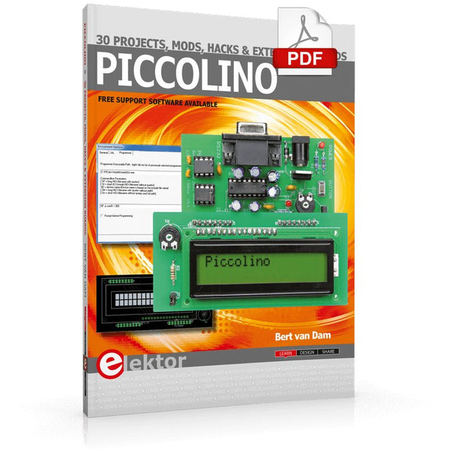
Elektor Digital Piccolino - 30 Projects, mods, hacks and extension (E-book)
The Piccolino rapid development board can be used to design microcontroller circuits quickly. The Piccolino has a fast 16f887 PIC microcontroller, voltage regulator, and communications module, and can be easily extended using its four headers. This e-book contains 30 projects based on the Piccolino. We'll use its unique communications facilities and get the Piccolino to communicate with programs on a PC. On the PC, we use the free programming language Small Basic. You can use this to create Windows programs with buttons and graphs quickly. You will learn how to analyze components such as inductors, capacitors, and OPAMPs, and how to display the measurement results in a graphical format. This will help you to design your circuits easily. We will then start to adapt to the Piccolino. We'll add components to it to make it more powerful, with extra features such as flow control and digital to analog conversion. The clear instructions will enable you to design and build your adaptations. This way you can make your custom designed Piccolino. We'll end up making an extension: a PCB that that can be mounted on the Piccolino headers. As an example, we'll design and build an extension for an LCD. You can use the included board layout to make your PCB or have it made for you. At the same time, you will learn how to make your extensions. The only limitation is your imagination! The clear descriptions along with circuit diagrams and photos, will make the building of these projects an enjoyable experience. Each project has a clear explanation of the reasons why it was designed in a particular way. This helps you learn a lot about the Piccolino, as well as Small Basic, and the components that are used in this e-book. You can adapt the projects to suit your requirements or combine several projects.
€ 34,95
Mitglieder: € 31,46
-

Sensepeek Sensepeek 4012 PCBite Kit inkl. 2x SP10 Sonde für DMM
PCBite ist die Komplettlösung für den Umgang mit Ihrer Leiterplatte während der Entwicklungsphase. Starke Magnete zusammen mit einer rostfreien Grundplatte machen das System flexibel, mobil und benutzerfreundlich. Der Halter kann leicht neu positioniert werden, um Leiterplatten unterschiedlicher Form und Größe zu handhaben. Die Sonden sind stabil und dennoch flexibel und eignen sich für sofortige Messungen oder den völlig freihändigen Betrieb zusammen mit Ihrem Multimeter oder Ihrem bevorzugten Werkzeug. Inbegriffen 4x PCBite-Halter 2x Bananen-zu-DuPont-Testkabel rot/schwarz 2x SP10-Sonde mit rot/schwarzem Sondenkopf und Prüfnadeln mit Stiftspitze 2x zusätzliche Testnadel mit Kronenspitze 1x Satz gelbe Isolierscheiben 1x große Grundplatte (A4) 1x Mikrofasertuch Downloads Benutzerhandbuch
€ 103,22
-

Elektor Digital Elektor Circuit Special 2026 (PDF) NL
Elektor GREEN en GOLD leden kunnen deze uitgave hier downloaden. Nog geen lid? Klik hier om een lidmaatschap af te sluiten. Een stroombron voor het testen van Z-diodesControle van Z-diodes van 1 tot 54 V bij 1 tot 50 mA ESD polsbandtesterEen testapparaat met indicatie voor ‘goed’, ‘grensgeval’ en ‘afgekeurd’ Testapparaat voor de respons op piekbelastingen van voedingenEen generator voor repeterende stapsgewijze belasting voor laboratoriumvoedingen Euclidische sequencer zonder microcontrollerTriggerpatronen en CV-sequenties met eenvoudige CMOS-logica LED-knipperlicht voor heksystemen en meer, inclusief geluidssignaal Printen nodig? De Elektor PCB-service staat voor u klaar Tandenborstel-timerMet een kleine PIC Een contactloos magnetisch combinatieslotMet de AS5600 rotatie-positie sensor Batterijgevoede ruisarme voorversterkervoor dynamische microfoons Het Arduino Nano testLabMeten, sturen en regelen Rhythmische basverlichtingBenadruk het ritme van je muziek Low-cut filterGeen risico op audio-terugkoppeling op uw systeem Nauwkeurige 1 Hz blokgolfgenerator voor breadboardsEen betrouwbare klokpuls op basis van CMOS 555 onderstebovenDutycycles tot nul Van Halfgeleidergids tot Circuit Specials65 jaar innovatie op het gebied van elektronica Elektrische isolatieCAN-interface met digitale isolator en voedingsmodule SpongillatorEen sponsgebaseerde oscillator Echte willekeurige getallengeneratorMet geïntegreerde chi-kwadraattoets 3D-viewer voor HTML-pagina'sEenvoudig en vrijwel zonder code Programmeren met TLScriptEen scripttaal voor metingen, tests en besturing Schakelingsontwerp: tips van experts FeedbackWat is het en waarom is het belangrijk? Eén board, eindeloze ideeën: Arduino UNO QVan retro-gaming tot realtime milieumonitoring Hoe u een donut-antenne repareert Standby-KillerEen echte aan/uit-schakelaar voor uw tv Batterijen testenBatterijen meten met de Arduino Nano Voeding voor audioversterkersEen goede voeding zonder netbrom HF prototype printplatenMaak zelf snel een prototype printplaat Type 3-overspanningsbeveiligingEen type 3-overspanningsbeveiliging voor uw gevoelige apparatuur IoT-kamerthermostaat boardMet een op ESP32-C3/S3 gebaseerde Xiao MCU-module Van star naar slimFlexibele en gedrukte elektronica, tussen visie en industriële realiteit
€ 9,95
-

Elektor Publishing Experimenting with Red Pitaya STEMlab Gen 2
Practical Projects and Programs With Experimenting with Red Pitaya STEMlab Gen 2, Red Pitaya goes beyond a versatile board. It becomes a powerful laboratory instrument for precision measurement, analysis, and control. From the fundamentals of electronic project development, monitoring, control, and design to testing, this book walks you step-by-step through everything you need to know to harness the full potential of Red Pitaya hardware and software. The book presents real-time, FPGA-based projects that are developed on a PC using the Vivado environment, then transferred to the Red Pitaya for execution and testing. You will learn about enhanced performance, expanded I/O capabilities, improved FPGA features, and advanced connectivity options that open up new frontiers for precision measurement, monitoring, and control in your embedded applications. Inside the book you will discover: A deep dive into Red Pitaya architecture and hardware design Electronic experiments using Red Pitaya for measurement and monitoring Hands-on projects using the Python programming language Practical guidance for FPGA programming using Red Pitaya Red Pitaya FPGA projects using the Verilog HDL under Vivado IDE Practical design of electronic projects including measurement and testing Step-by-step examples that bridge theory and real-world implementation Whether you are designing your own electronic circuits, developing signal analysis tools, or creating real-time control or monitoring systems, this book provides you the knowledge and confidence you need to fully learn and customize the Red Pitaya platform.
€ 39,95€ 32,95Bestpreis
-

Holybro Holybro QAV 250 ARF Drohnen-Kit
Das QAV250-Kit ist der perfekte Einstieg in die Entwicklung auf PX4 oder Ardupilot. Es kombiniert einen Carbonfaser-250-Rennrahmen und wichtige Elektronik mit dem Mini-Autopiloten Pixhawk 6C. Der Bausatz ist einfach zu montieren, Löten ist nicht erforderlich. Technische Daten Micro-Leistungsmodul (PM06 v2) Motoren: 2207 KV1950 Radstand: 250 mm Abmessungen: 198 x 235 x 70 mm Gewicht: 347 g Lieferumfang Carbonfaser-250-Flugzeugzelle mit Hardware Micro-Leistungsmodul (PM06 v2) Motoren: 2207 KV1950 5" Kunststoff-Requisiten Vollständig montiertes Power Management Board mit ESCs (BLHeli S ESC 20A) Akkugurte Hinweis: Der LiPo-Akku ist nicht im Lieferumfang enthalten.
€ 214,95
Bestpreis
-
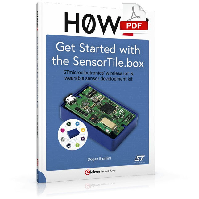
Elektor Digital H0W2: Get Started with the SensorTile.box (E-book)
STmicroelectronics’ wireless IoT & wearable sensor development kit ‘SensorTile.box’ is a portable multi-sensor circuit board housed in a plastic box and developed by STMicroelectronics. It is equipped with a high-performance 32-bit ARM Cortex-M4 processor with DSP and FPU, and various sensor modules, such as accelerometer, gyroscope, temperature sensor, humidity sensor, atmospheric pressure sensor, microphone, and so on. SensorTile.box is ready to use with wireless IoT and Bluetooth connectivity that can easily be used with an iOS or Android compatible smartphone, regardless of the level of expertise of the users. SensorTile.box is shipped with a long-life battery and all the user has to do is connect the battery to the circuit to start using the box. The SensorTile.box can be operated in three modes: Basic mode, Expert mode, and Pro mode. Basic mode is the easiest way of using the box since it is pre-loaded with demo apps and all the user has to do is choose the required apps and display or plot the measured data on a smartphone using an app called STE BLE Sensor. In Expert mode users can develop simple apps using a graphical wizard provided with the STE BLE Sensor. Pro mode is the most complex mode allowing users to develop programs and upload them to the SensorTile.box. This book is an introduction to the SensorTile.box and includes the following: Brief specifications of the SensorTile.box; description of how to install the STE BLE Sensor app on an iOS or Android compatible smartphone required to communicate with the box. Operation of the SensorTile.box in Basic mode is described in detail by going through all of the pre-loaded demo apps, explaining how to run these apps through a smartphone. An introduction to the Expert mode with many example apps developed and explained in detail enabling users to develop their own apps in this mode. Again, the STE BLE Sensor app is used on the smartphone to communicate with the SensorTile.box and to run the developed apps. The book then describes in detail how to upload the sensor data to the cloud. This is an important topic since it allows the sensor measurements to be accessed from anywhere with an Internet connection, at any time. Finally, Pro mode is described in detail where more experienced people can use the SensorTile.box to develop, debug, and test their own apps using the STM32 open development environment (STM32 ODE). The Chapter explains how to upload the developed firmware to the SensorTile.box using several methods. Additionally, the installation and use of the Unicleo-GUI package is described with reference to the SensorTile.box. This PC software package enables all of the SensorTile.box sensor measurements to be displayed or plotted in real time on the PC.
€ 29,95
Mitglieder: € 26,96
-

Sensepeek Sensepeek 4003 PCBite Kit inkl. 4x SP10-Sonde und Testdrähten
Das minimalistische Design und die federbelastete Prüfnadel ermöglichen die gleichzeitige Messung von Fine-Pitch-Komponenten und nahegelegenen Signalen. Die Sonde ist stabil und dennoch flexibel und eignet sich für sofortige Messungen oder völlig freihändigen Betrieb zusammen mit Ihrem Multimeter, Logikanalysator oder Ihrem bevorzugten Werkzeug. Der Dual-Pin-Header-Stecker passt direkt auf einen 2,54-mm-Stecker (0,100 Zoll). Der SP10 verfügt wie alle PCBite-Sonden und -Halter über einen starken Magneten in der Basis, der das Platzieren und Neupositionieren der Sonde erleichtert. Inbegriffen 4x PCBite-Halter 1x große Grundplatte (A4) 4x PCBite-Sonde mit Testnadel mit Stiftspitze 4x zusätzliche Prüfnadel mit Kronenspitze 1x Satz gelbe Isolierscheiben 5x Dupont-zu-Dupont-Testkabel 2x Bananen-zu-Dupont-Testkabel 1x Mikrofasertuch Downloads Benutzerhandbuch
€ 149,94
-
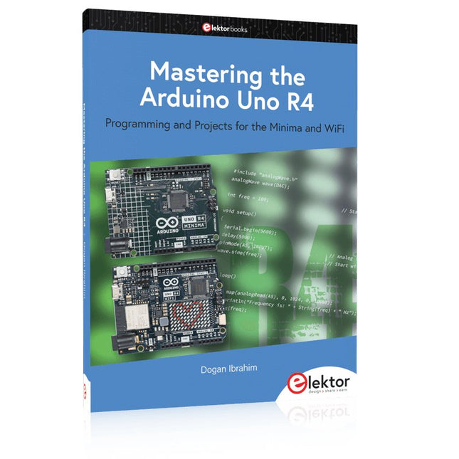
Elektor Publishing Mastering the Arduino Uno R4
Programming and Projects for the Minima and WiFi Based on the low-cost 8-bit ATmega328P processor, the Arduino Uno R3 board is likely to score as the most popular Arduino family member, and this workhorse has been with us for many years. Eleven years later, the long-overdue successor, the Arduino Uno R4, was released. It is built around a 48 MHz, 32-bit Arm Cortex-M4 microcontroller and provides significantly expanded SRAM and Flash memory. Additionally, a higher-precision ADC and a new DAC are added to the design. The Uno R4 board also supports the CAN Bus with an interface. Two versions of the board are available: Uno R4 Minima, and Uno R4 WiFi. This book is about using these new boards to develop many different and interesting projects with just a handful of parts and external modules. All projects described in the book have been fully tested on the Uno R4 Minima or the Uno R4 WiFi board, as appropriate. The project topics include the reading, control, and driving of many components and modules in the kit as well as on the relevant Uno R4 board, including LEDs 7-segment displays (using timer interrupts) LCDs Sensors RFID Reader 4x4 Keypad Real-time clock (RTC) Joystick 8×8 LED matrix Motors DAC (Digital-to-analog converter) LED matrix WiFi connectivity Serial UART CAN bus Infrared controller and receiver Simulators … all in creative and educational ways with the project operation and associated software explained in great detail.
€ 44,95
Mitglieder: € 40,46
-

Sensepeek Sensepeek 6012 PCBite Kit inklusive 2x SQ10 Sonde für ein DMM
Die SQ-Serie der berührungslosen PCBite-Sonden von Sensepeek ist isoliert, wird mit farbcodierten Kabelhaltern geliefert und hat einen niedrigeren Schwerpunkt, was sie im Vergleich zur ursprünglichen SP-Serie der Sonden noch stabiler macht. Alle beliebten Funktionen der berührungslosen Messung, austauschbare feinrastende Testnadeln und das minimalistische Design werden beibehalten, um herkömmliche Proben in Standardgröße und handgehaltene Sonden überflüssig zu machen. Features Alle berührungslosen Sonden von Sensepeek ermöglichen schnelle Messungen oder lange Trigger-Sessions. Kein Löten von Drähten, um Ihre Sonde anzuschließen, oder komplizierte Werkzeuge zur Einrichtung erforderlich. Platzieren Sie einfach die Probennadel an einem beliebigen Prüfpunkt oder Bauteil im Signalfad und lassen Sie sie los. Spart Zeit und Frustration bei Entwicklung, Überprüfung und Reparaturen. Das minimalistische Design und die federbelastete Testnadel ermöglichen gleichzeitige Messungen an feinrastenden Komponenten und benachbarten Signalen. Sowohl die Länge als auch das Gewicht der SQ-Sonden sind perfekt ausbalanciert, um sie mit den PCBite-PCB-Haltern und der Basisplatte zu verwenden, die für die berührungslose Funktion unerlässlich sind. Der Sondenhalter hat einen leistungsstarken Magneten in der Basis, wie bei allen PCBite-Sonden und -Haltern, wodurch die Sonde einfach platziert und neu positioniert werden kann. Die SQ-Serie der Sonden kann auch handgehalten ohne den Sondenhalter verwendet werden, da sie über einen isolierten Griff verfügen. Ihr volles Potenzial wird jedoch bei berührungsloser Messung genutzt. Lieferumfang 4x PCBite Platinenhalter 2x SQ10-Sonden und Prüfnadeln mit Stiftspitze (rot/schwarz) 2x Bananen-zu-Dupont-Testkabel (rot/schwarz) 1x Große Grundplatte (A4) 1x Isolierabdeckung für die Grundplatte (A4) 1x Satz gelbe Isolierscheiben für die Leiterplattenhalter 1x Satz Kabelhalter (rot/schwarz) 2x Zusätzliche Testnadeln 1x Mikrofasertuch Downloads User Guide (PCBite Kit) User Guide (SQ10)
€ 124,95
-

Elektor Labs Elektor Rauscharmes Labornetzteil
Das rauscharme Labornetzteil von Elektor ist ein vollständig analoges, einstellbares, symmetrisches Gerät mittlerer Leistung, das ohne Schalt- oder digitale Komponenten auskommt. Es bietet eine Ausgangsspannung, die zwischen 0 V und ±22 V einstellbar ist, sowie einen Ausgangsstrom, der von 0 A bis 1 A eingestellt werden kann. Da auf jegliche Art von Schalttechnik verzichtet wird, liefert das Design extrem geringes Rauschen. Zur Anzeige beider Ausgangsspannungen und -ströme werden vier kleine analoge Einbauinstrumente mit Drehspulmesswerk verwendet. Die meisten modernen Labornetzgeräte und AC-Adapter arbeiten mit Schaltnetzteiltechnik. Selbst die besten Ausführungen weisen zwangsläufig hochfrequente Restwelligkeit und andere Schaltartefakte am Ausgang auf, die die Prüfung empfindlicher analoger Schaltungen stören und Messungen kleiner Signale beeinträchtigen können. Um dieses Problem zu vermeiden, setzt dieses Konzept auf ein vollständig analoges Netzgerät. Obwohl es weniger effizient ist als vergleichbare Schaltnetzteile, spielt die geringere Effizienz beim Einsatz auf dem Prüfstand kaum eine Rolle und sorgt für sauberere und zuverlässigere Messergebnisse. Da viele analoge Schaltungen eine symmetrische Versorgung benötigen, liefert dieses Design positive und negative Ausgangsspannungen gleicher Höhe. Eine geringfügige Nachjustierung ist möglich, um eventuelle Ungleichgewichte auszugleichen. Selbstverständlich ist auch eine einstellbare Strombegrenzung integriert. Das Kit enthält die für den Aufbau des Netzteils erforderlichen Komponenten, mit Ausnahme der Transformatoren. Technische Daten Ausgangsspannung 0…+22 V, 0, −22 V Ausgangsstrom 0…+1 A, 0…−1 A Rauschen −85 dBV (bei 0,95 A/20 V, B = 22 kHz) −84 dBV (bei 0,95 A/20 V, B > 500 kHz) Restwelligkeit 50 µVRMS (bei 950 mA/20 V, B = 22 kHz, hauptsächlich 100-Hz-Anteil) Lieferumfang 3x Platinen: Regler (PCB-1), Netzfilter (PCB-2) und Transformator (PCB-3) Alle Bauteile mit Ausnahme der Netztransformatoren 4x Drehspulmesswerke Zusätzliche Teile für die Verdrahtung (Drähte, Bananenbuchsen, Kaltgeräte-Netzmodul usw.) Nicht enthalten Die drei Netztransformatoren Ein Gehäuse Stückliste Für die Spannungsregler-Platine (240386-1) Widerstände (250 mW, 1%) R1 = 12 Ω R2, R8, R37, R62 = 1 MΩ R3, R7, R10, R13, R17, R20, R22, R30, R35, R42, R45, R47, R55, R60 = 100 Ω, 600 mW R4, R5 = 4.7 kΩ R6 = 100 kΩ R9, R12, R14, R36, R38, R39, R61, R63, R66, R72, R78, R79 = 10.0 kΩ, 600 mW R11 = 9.76 kΩ, 600 mW R15, R40 = 44.2 kΩ, 600 mW R16, R41, R77 = 1 kΩ R18, R43 = 1.5 kΩ, 1 W, 5% R19, R44 = 470 Ω, 1 W, 5% R21, R46 = 330 Ω, 600 mW R23, R24, R48, R49 = 1.0 Ω, 1 W R25, R50 = 1 kΩ, 1 W, 5% R26, R28, R51, R53 = 1.000 kΩ 0.1%, 15 ppm/C R27, R29, R52, R54 = 10.00 kΩ 0.1%, 15 ppm/C R31, R56 = 1.2 kΩ, 1 W, 5% R32, R57 = 47 kΩ R33, R58 = 270 Ω R34, R59 = 27 kΩ R64, R69 = 12.0 kΩ R65 = 3.0 kΩ, 600 mW R67, R80 = 470 Ω, 600 mW R68, R70 = 6.8 kΩ, 600 mW R71 = 30.0 kΩ,, 600 mW R73, R74, R75, R76 = 10 MΩ P1, P2, P3 = 10 kΩ, 200 mW, 20%, potentiometer, 1 turns, single, lin., panel mount P4, P5 = 500 Ω, 500 mW, 10%, trimmer, 25 turns, 3296Y-1-501LF Bourns P6, P7 = 10 kΩ, 500 mW, 10%, trimmer, 25 turns, 3296Y-1-501LF Bourns Kondensatoren C1 = 100 nF, 50 V, 10%, ceramic X7R, LS 5 mm C2, C3, C6, C7, C30 = 10 µF, 63V, 20%, LS 2.5 mm, 3000hours@105°C C4, C5, C8, C9, C13, C14, C18, C19, C23, C24, C28, C29, C31, C32, C38, C39 = 100 nF, 250 V, 10%, PET, LS 7.5 mm C10, C20 = 47 nF, 100 V, 5%, PET, LS 5 mm C11, C21 = 10 nF, 100 V, 5%, PET, LS 5 mm C12, C22 = 220 µF, 35 V, 20%, 0.024 Ω, LS2.5/3.5 mm, Ir 3.4 A, 2000hours@125°C, polymer C15, C25 = 120 µF, 50 V, 20%, ESR 0.02 Ω, Diam. 10 mm max., LS 5 mm C16, C26 = 15 nF, 100 V, 5%, PET, LS 5 mm C17, C27 = 47 nF, 100 V, 5%, PET, LS 5 mm C33, C34 = 22 µF, 50 V, 20%, LS 2 mm, 10000 hours @ 105°C C35, C36, C44, C45 = 1 µF, 100 V, 10%, LS 5 mm, ceramic X7R C37 = 100 uF, 50 V, 20%. LS 3.5 mm C40, C41, C42, C43, C46, C47, C48, C49 = 1000 µF, 50 V, 20%, LS 5/7.5 mm, Ir 3.32 A, 10000hours@105°C, D 16 mm C50, C51, C52, C53 = 47 nF, 100 V, 10%, ceramic X7R, LS 5 mm Induktivitäten L1, L2 = 4.7 µH, 3.2 A, 0.033 Ω, LS 5 mm, RLB0914-4R7ML Bourns L3 = Commom mode choke, 14.5 mH, 3 A, SSRH24NH-30145 Kemet Halbleiter D1, D2, D3, D4, D5, D9, D10, D11, D15 = BAT85, DO-34 D6, D7, D12, D13 = SR560, DO-201AD D8, D14, D16 = 1N4148, DO-35 D17 = Zenerdiode, 5.6 V, 0.5 W, DO-41 D18, D19 = 1N4004, DO-41 D20, D21 D22, D23 = V30100CI-M3/P, dual common cathode, TO-220 D24 = Zener diode, 30 V, 1 W, DO-41 LED1, LED2 = LED, red, T-1 (3 mm) LED3, LED4 = LED, green, T-1 (3 mm) TVS1, TVS2 = BZW50-33B, R6 T1, T2, T4 = BC337.25, TO-92 T3 = NJW0302G, TO-3P T5, T6, T8 = BC327.25, TO-92 T7 = NJW0281G, TO-3P T9 = BD139, TO-126 (SOT-32) IC1 = LM334Z, TO-92 IC2 = LM4040AIZ-5.0/NOPB, TO-92 (TO-226AA-3) IC3, IC4 = OPA2992IDR, SOIC-8 IC5, IC6 = OPA4992IDR, SOIC-14 IC7 = OPA992IDBVR, SOT-23-5 IC8 = LM339N, DIP-14 IC9 = LM317, TO-220 IC10 = LM337, TO-220 Sonstiges F1, F2 = 5×20 mm fuse, 1.6 A, fast acting HS1, HS2 = Heatsink MC33271 (for T3/T7), 2.7°C/W, PCB mount, height 63.5 mm K1, K4 = 3-way screw terminal block, LS 3.5 mm, max. 1.5 mm² K2, K3 = 3-way screw terminal block, LS 3.5 mm, max. 1 mm² M1, M3 = Moving coil meter, Range 30 V, type 91C4, 45×45 mm M2, M4 = Moving coil meter, Range 1 A, type 91C4, 45×45 mm² RE1 = Relay DPDT,5V, UA2-5NU Verschiedenes 3× 3-way screw terminal block, LS 3.5 mm, max. 1 mm² (for P1, P2, P3) 4× Pin header, 1×2, vertical, pitch 2.54 mm (for LED1, LED2, LED3, LED4) 4× Pin socket, 1×2, vertical. pitch 2.54 mm (for LED1, LED2, LED3, LED4) 2× Heatsink FK222SA220, 20°C/W, PCB mount (for IC9 & IC10) 2× Mica thermal pad for TO-220, 12×18×0.05 mm (for IC9 & IC10) 2× Insulating bushing IB 6, TO-220 (for IC9 & IC10) 2× Ceramic thermal pad, 23×20×2 mm (for T3 & T7) 2× PCB Fuse Holder, for 5×20 mm fuse, 10 A (for F1, F2) 2× Cover for PCB Fuse Holder, transparent (for F1, F2) 2× 2-way screw terminal block, LS 3.5 mm, max. 1 mm² (for M1 & M3) 2× 2-way screw terminal block, LS 3.5 mm, max. 1.5 mm² (for M2 & M4) 8× M3 solder lug, thickness 0.35 mm (for M1…M4) M4 solder lug, thickness 0.35 mm (to connect 4 mm banana connectors) Screened cable, 1 pair, 2×24 AWG/0.22 mm², 1 m (for P1, P2 & P3) IC socket, DIP, 14 contacts (for IC8) M3 washer, plain, steel M3 screw, 16 mm, steel, pan head M3 nut M3 spring washer 50 mm M3 standoff, steel, male-female 12 mm M3 standoff, steel, male-female 10 mm M3 standoff, steel, male-female M3 screw, 8 mm, steel, pan head Für die Netzfilter-Platine (240386-2) Widerstand R1 = 220 kΩ, 1 W, 500 V, 5% Kondensatoren C1, C2 = 470 nF, 305 VAC, Class X2, 11 × 27 mm max., LS 15/22.5 mm C3, C4, C5, C6 = 2.2 nF, 300 VAC, Class Y2, 13 × 4 mm, LS 10 mm, PP Induktivitäten L1, L2 = Common-mode choke, 6.8 mH, 1.7 A, TDK B82732R2172B030 Halbleiter MOV1 = TVS varistor, 300 VAC, S14K300 (230 VAC, B72214S0301K101) and SK14K150 (150 VAC, B72214S0151K101) Sonstiges K1, K2 = 3-way screw terminal block, LS 7.62 mm F1 = Time-delay fuse, 0.5 A (230 VAC) or 1 A (115 VAC) Verschiedenes 1× Fuse holder, 5×20 mm, 10 A, 500 VAC 1× Transparent fuse cover 4× 10 mm M3 standoff, steel, male–female 4× M3 screw, 8 mm, steel, pan head 4× M3 nut Für die Transformator-Platine (240386-3) Widerstände R1, R2 = 2.7 kΩ, 600 mW, 1% R3 = 10.0 kΩ, 600 mW, 1% Kondensator C1 = 220 µF, 50 V, 20%, Ø10 mm, LS 5 mm, 4000 h @ 105°C Transformatoren (nicht im Lieferumfang dieses Kits enthalten!) TR1, TR2, TR3 = 2×7 V, 25 VA, PCB-mounted toroid, 70060K Talema Halbleiter D1–D4 = 1N4148, DO-35 D5, D6 = 1N4004, DO-41 D7 = Zener 5.6 V, 1.3 W, DO-41 LED1 = LED, red, T-1 (3 mm) IC1, IC2 = MOC8021M, CTR ≥ 1000%, DIP-6 Sonstiges F1, F2, F3 = 160 mA time-delay fuse (230 VAC) or 315 mA time-delay fuse (115 VAC) K1 = 2-way screw terminal block, LS 7.62 mm K2 = 3-way screw terminal block, LS 3.5 mm, max 1.5 mm² K3, K4 = 3-way screw terminal block, LS 3.5 mm, max 1 mm² RE1, RE2 = Relay DPDT, 5 A/250 VAC / 24 VDC Verschiedenes 1× Pin header 1×2, pitch 2.54 mm + matching socket for LED1 3× Fuse holder 5 × 20 mm, 10 A, 500 VAC + transparent cover 3× M4 screw, 8 mm, pan head + washer for TR1-TR3 8× M3 screw, 8 mm, pan head + nut + washer 8× 10 mm M3 standoff, steel, male–female 2× IC socket, DIP-6 for IC1 & IC2 Weitere Bauteile 1 m red insulated wire, stranded, 1.5 mm² 0.5 m blue insulated wire, stranded, 1.5 mm² 0.5 m black insulated wire, stranded, 1.5 mm², 0.5 m 2 m red insulated wire, stranded, D 0.56 mm (0.25 mm²) 2 m black insulated wire, stranded, D 0.56 mm (0.25 mm²) 0.5 m Multicore Cable, Flexible, 3 Core, 0.75 mm² (24 x 0.2 mm) Red banana socket Black banana socket Blue banana socket Green banana socket IEC Power Entry Module with switch, IEC C14 3 crimp terminals, FASTON, 4.75 x 0.81 mm 3 knobs Links Elektor Labs JumpStarter Page Artikel (Teil 1) Artikel (Teil 2)
€ 299,00€ 249,00Bestpreis
-

Elektor Digital Programming with STM32 Nucleo Boards (E-book)
STM32 Nucleo family of processors are manufactured by STMicroelectronics. These are low-cost ARM microcontroller development boards. This book is about developing projects using the popular Nucleo development board. In the early chapters of the book, the architecture of the Nucleo family is briefly described. Software development tools that can be used with the Nucleo boards such as the Mbed, Keil MDK, TrueSTUDIO, and the System Workbench are described briefly in later Chapters. The book covers many projects using most features of the STM32 Nucleo development boards where the full software listings for Mbed and System Workbench are given for every project. The projects range from simple flashing LEDs to more complex projects using modules and devices such as GPIO, ADC, DAC, I²C, LCD, analog inputs and others. In addition, several projects are given using the Nucleo Expansion Boards, including popular expansion boards such as solid-state relay, MEMS and environmental sensors, DC motor driver, Wi-Fi, and stepper motor driver. These Expansion Boards plug on top of the Nucleo development boards and simplify the task of project development considerably. Features of this book Learn the architecture of the STM32 microcontrollers Learn how to use the Nucleo development board in projects using Mbed and System Workbench Toolchains Learn how to use the Nucleo Expansion Boards with the Nucleo development boards Update The Mbed compiler has been replaced with two software packages: The Mbed Studio and Keil Studio Cloud. Both of these software packages are free of charge and are available on the Internet. If you need assistance using the Keil Studio Cloud, please download the Guide below.
€ 34,95
Mitglieder: € 31,46
-
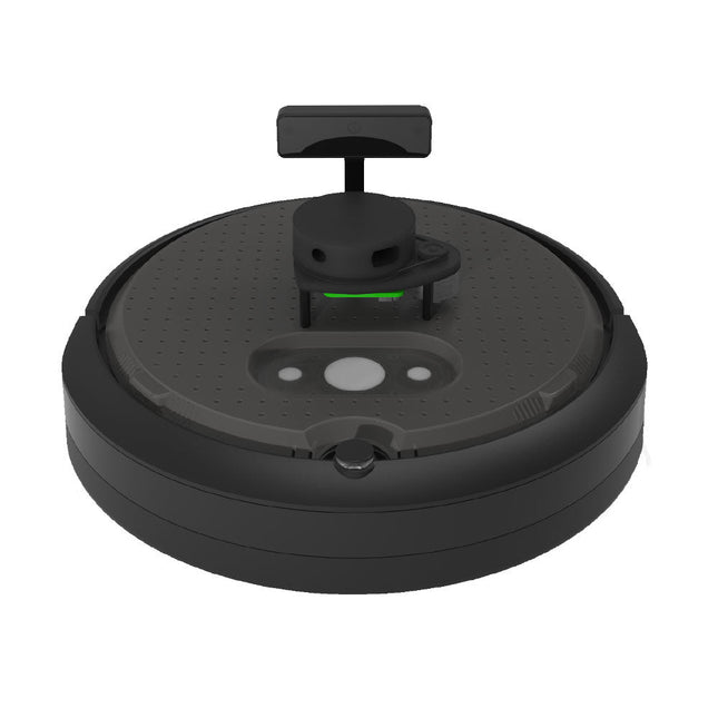
Clearpath Robotics Clearpath Robotics TurtleBot 4 Lite
TurtleBot 4 ist die nächste Generation der weltweit beliebtesten Open-Source-Robotikplattform für Bildung und Forschung und bietet bessere Rechenleistung, bessere Sensoren und ein erstklassiges Benutzererlebnis zu einem erschwinglichen Preis. TurtleBot 4 Lite ist mit einer mobilen iRobot Create 3-Basis, einem leistungsstarken Raspberry Pi 4 mit ROS 2, einer räumlichen KI-Stereokamera OAK-D, 2D LiDAR und mehr ausgestattet. Alle Komponenten wurden nahtlos integriert, um eine sofort einsatzbereite Entwicklungs- und Lernplattform zu bieten. Technische Daten Basisplattform iRobot Create 3 Räder (Durchmesser) 72 mm Bodenfreiheit 4,5 mm Bordcomputer Raspberry Pi 4 (4 GB) Maximale Lineargeschwindigkeit 0,31 m/s im abgesicherten Modus0,46 m/s ohne abgesicherten Modus Maximale Winkelgeschwindigkeit 1,90 rad/s Maximale Nutzlast 9kg Betriebszeit 2h 30m – 4h je nach Belastung Ladezeit 2h 30m Lidar RPLIDAR A1M8 Kamera OAK-D-Lite Benutzerleistung VBAT @1,9 A5 V @ Schwachstrom3,3 V @ Schwachstrom USB-Erweiterung 2x USB 2.0 (Typ A)2x USB 3.0 (Typ A) Programmierbare LEDs Erstelle 3 Lichtringe Tasten und Schalter 2x Create 3 User Buttons1x Create 3 Power Button Batterie 26 Wh Lithium-Ionen (14,4 V nominal) Ladestation Inbegriffen Größe (L x B x H) 342 x 339 x 192 mm Gewicht 3,3 kg Downloads User Manual
€ 1.699,00
Bestpreis


