
Suchergebnisse für "fnirsi OR lcr OR p1 OR multi OR function OR transistor OR tester"
-
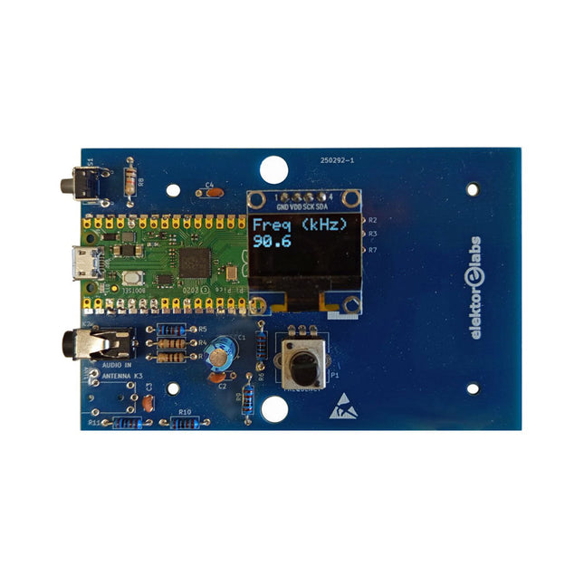
Elektor Labs Elektor AM-Sender-Kit
Bauen Sie Ihren eigenen Vintage-Radiosender Das Elektor AM-Sender-Kit ermöglicht das Streamen von Audio auf Vintage-AM-Radioempfänger. Basierend auf einem Raspberry Pi Pico Mikrocontroller-Modul kann der AM-Sender auf 32 Frequenzen im AM-Band senden, von 500 kHz bis 1,6 MHz in 32 Schritten von ca. 35 kHz. Die Frequenz wird mit einem Potentiometer gewählt und auf einem 0,96" OLED-Display angezeigt. Eine Taste ermöglicht das Umschalten des Sendemodus zwischen Ein und Aus. Die Reichweite des Senders hängt von der Antenne ab. Die integrierte Antenne bietet eine Reichweite von wenigen Zentimetern, sodass der AM-Sender nahe am Radio oder im Radio selbst platziert werden muss. Eine externe Loop-Antenne (nicht enthalten) kann angeschlossen werden, um die Reichweite zu erhöhen. Das Elektor AM-Sender-Kit wird als Bausatz geliefert, den Sie selbst auf die Platine löten müssen. Features Die Platine ist kompatibel mit einem Hammond-1593N-Gehäuse (nicht enthalten).Ein 5-VDC-Netzteil mit Micro-USB-Anschluss (z. B. ein altes Handy-Ladegerät) wird benötigt, um das Kit zu betreiben (nicht enthalten). Stromaufnahme: 100 mA. Die Arduino-Software (benötigt Earle Philhowers RP2040-Boards-Paket) für das Elektor-AM-Sender-Kit sowie weitere Informationen sind auf der Elektor-Labs-Seite dieses Projekts verfügbar. Stückliste Widerstände R1, R4 = 100 Ω R2, R3, R8 = 10 kΩ R5, R6, R9, R10, R11 = 1 kΩ R7 = optional (nicht enthalten) P1 = Potentiometer 100 kΩ, linear Kondensatoren C1 = 22 µF 16V C2, C4 = 10 nF C3 = 150 pF Sonstiges K1 = 4×1 Stiftleiste K2, K3 = 3,5-mm-Buchse Raspberry Pi Pico Drucktaste, Winkelmontage 0,96" monochromes I²C-OLED-Display Leiterplatte 150292-1
€ 34,95€ 29,95Bestpreis
-
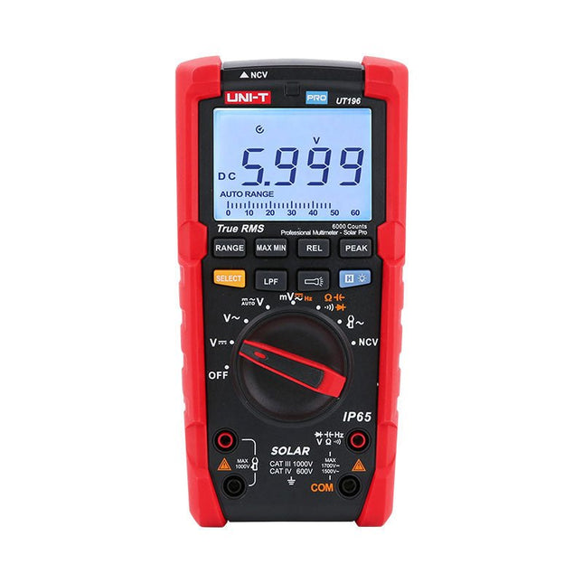
Uni-Trend UNI-T UT196 True RMS Solar-Multimeter
Das UT196 True RMS Solar-Multimeter UT196 ist ein ideales Werkzeug für die Wartung von Solarstromanlagen. Dieses robuste Messgerät wurde für Techniker entwickelt, die in rauen Außenumgebungen arbeiten. UT196 kann Spannungen bis zu 1700 V DC und 1500 V AC sowie 3000 A AC Strom mit einem externen Stromzangensensor messen. Dieses Solarmessgerät bietet IP65-Schutz und übersteht auch Stürze aus 2 m Höhe. Das UT196 Solar-Multimeter ist mit einem Überlastschutz für 1700 V DC und 1500 Vrms AC ausgestattet und für den sicheren Einsatz in CAT III 1000 V und CAT IV 600 V Umgebungen getestet. Features True RMS Messen Sie bis zu 1700 V DC und 1500 V AC für Hochspannungsanwendungen, z. B. Solaranlage, Wind IP65-Schutz CAT III 1000 V, CAT IV 600 V Analogleiste Frequenzgang: 45 Hz ~ 1 kHz Tiefpassfilterfunktion Niederimpedanzmodus Eingebautes Blitzlicht, helle Hintergrundbeleuchtung und visueller Alarm Anwendungen Messung hoher Gleichspannungen Messung von Ausgangsspannung und Frequenz Spannungs- und Frequenzmessung Strom- und Frequenzmessung Technische Daten Bereich UT196 Gleichspannung (V) 1700 V ±0,2% +5 Wechselspannung (V) 1500 V ±0,8% +3 Frequenz (Hz) 1 MHz ±0,08% +4 Widerstand (Ω) 60 MΩ ±0,8% +2 Kapazität (F) 60 mF ±1,9% +5 Stromversorgung 9-V-Batterie Abmessungen 195 x 95 x 58 mm Lieferumfang UT196 Solar-Multimeter Batterie Prüfkabel Downloads Datasheet Manual
€ 127,49
-

Elektor Digital Elektor Circuit Special 2026 (PDF) DE
Diese Ausgabe steht allen GOLD- und GREEN-Mitgliedern auf der ElektorMagazine-Website zum Download bereit! Sie sind noch kein Mitglied? Hier klicken! Stromquelle zum Testen von (Z-)DiodenPrüfen von Z-Dioden von 1 bis 54 V bei 1 bis 50 mA ESD-Armband-TesterEin Tool zur Funktionsprüfung von Erdungsarmbändern Transientenmesser für LabornetzteileEin reproduzierbarer Lastsprung-Generator für Labornetzteile 3D-Viewer für HTML-SeitenEinfach und fast ohne Code LED-Blinkleuchte für Tore und mehr mit akustischem Alarm Benötigen Sie Leiterplatten? Der Elektor-Leiterplattenservice ist für Sie da. Zahnbürsten-TimerMit einem kleinen PIC Ein berührungsloses magnetisches Kombinationsschlossmit dem AS5600-Drehpositionssensor Rauscharmer, batteriebetriebener Vorverstärkerfür dynamische Mikrofone Das Arduino Nano TestLabMessen, Steuern, Regeln Rhythmische BassleuchteBetonen Sie den Rhythmus Ihrer Musik Low-cut-FilterKein Risiko von Audio-Rückkopplungen in Ihrem System Präziser 1-Hz-Rechteckwellengenerator für SteckbrettEine zuverlässige CMOS-basierte Taktquelle 555 auf den Kopf gestelltTastverhältnisse bis hinunter auf Null Vom „Halfgeleidergids“ zu Circuit Specials65 Jahre Elektronik-Innovation Galvanische TrennungCAN-Schnittstelle mit Digitalisolator und Powermodul SpongillatorEin schwammbasierter Oszillator Echter Zufallszahlengeneratormit integriertem Chi-Quadrat-Test Euklidischer Sequencer ohne MikrocontrollerTrigger-Pattern und CV-Sequenzen mit einfacher CMOS-Logik Programmieren mit TLScriptEine Skriptsprache zum Messen, Testen und Steuern Schaltungsdesign: Tipps von Experten RückkopplungWas ist das und warum ist sie wichtig? Ein Board, endlose Ideen: Arduino UNO QVon Retro-Gaming zur Echtzeit-Umweltüberwachung So bringen Sie eine Donut-Antenne in Ordnung Standby-KillerEin echter Ein-/Ausschalter für den Fernseher Akkus im TestAkkus vermessen mit dem Arduino Nano Stromversorgung für Audio-EndstufenEin gutes Netzteil ohne Netzbrummen Lochrasterplatinen für HFSchnelle Aufbauten mit DIY-Prototyping-Boards T3-ÜberspannungsschutzEin Typ-3-Schutzmodul für empfindliche Geräte IoT-Raumthermostat-Platinemit dem Xiao-MCU-Modul auf Basis des ESP32-C3/S3 Von starr zu smartFlexible und gedruckte Elektronik – zwischen Vision und industrieller Realität
€ 11,90
-

Elektor Digital Red Pitaya for Test and Measurement (E-book)
The Red Pitaya (STEMlab) is a credit card-sized, open-source test and measurement board that can be used to replace most measurement instruments used in electronics laboratories. With a single click, the board can transform into a web-based oscilloscope, spectrum analyser, signal generator, LCR meter, Bode plotter, and microcontroller. The Red Pitaya (STEMlab) can replace the many pieces of expensive measurement equipment found at professional research organisations and teaching laboratories. The device, that based on Linux, includes an FPGA, digital signal processing (DSP), dual core ARM Cortex processor, signal acquisition and generation circuitry, micro USB socket, microSD card slot, RJ45 socket for Ethernet connection, and USB socket – all powered from an external mains adaptor. This book is an introduction to electronics. It aims to teach the principles and applications of basic electronics by carrying out real experiments using the Red Pitaya (STEMlab). The book includes many chapters on basic electronics and teaches the theory and use of electronic components including resistors, capacitors, inductors, diodes, transistors, and operational amplifiers in electronic circuits. Many fun and interesting Red Pitaya (STEMlab) experiments are included in the book. The book also makes an introduction to visual programming environment. The book is written for college level and first year university students studying electrical or electronic engineering.
€ 29,95
Mitglieder: € 26,96
-

Elektor Digital Elektor November/December 2021 (PDF)
BEELDVERWERKING MET DE NVIDIA JETSON NANO (DEEL 2)Beeldherkenning met Edge Impulse NIEUWS VAN ELEKTOR JUMPSTARTERNieuwe campagnes EEN OPEN SOURCE-PLATFORM VOOR GPS-TRACKINGMet Traccar voertuigen volgen zonder gebruik te maken van een cloudserver JOY-IT LCR-T7 MULTIFUNCTIONELE TESTERVoor passieve componenten, discrete halfgeleiders en IR RUISSYNTHESIZERVan ruis naar muziek met de PRBSynth1 ALLE BEGIN......speelt verder met de spoel KENNISMAKING MET NEURONEN IN NEURALE NETWERKEN (DEEL 2)Logische Neuronen BEVEILIGINGSPROBLEMEN? BESTRIJD VUUR MET VUUR!Met flitslampje beveiligde analoge geheugenuitbreiding voor de verzendbox met manipulatie-indicatie LCR METER POSTER BLUETOOTH-BAKENS IN DE PRAKTIJKindoor-plaatsbepaling PROGRAMMEREN IN C OP DE RASPBERRY PICommunicatie via WiFi (een hoofdstuk als voorbeeld) EMC PRE-COMPLIANCE TEST VOOR UW DC-GEVOED PROJECT (DEEL 2)De hardware en het gebruik ervan KENNISMAKING MET DE PARALLAX PROPELLER 2 (DEEL 5)Smart Pin-Functie MODBUS VIA WLAN (DEEL 1)Hardware en programmering OOST WEST LAB BEST... waar de Junior Computer weer tot leven is gewekt BOUW ZELF EEN NAUWKEURIGE KALIBRATOR-10 V tot +10 V, 0 tot 40 mA, 0,001% REVIEW: ARDUINO NANO RP2040 CONNECTRaspberry Pi RP2040 + WiFi + Bluetooth DE FYSIEKE KANT VAN KUNSTMATIGE INTELLIGENTIE PROJECT 2.0Correcties, Updates en Brieven van lezers MAAK GUI'S MET PYTHONIntroductie in guizero CO2-METER-BOUWKIT VOOR IN DE KLASEen ESP8266-project van de University of Applied Sciences Aachen NOSTALGISCHE MK484 MW/LW-RADIO...Altijd leuk om te bouwen! ELEKTOR @ 60Laat er licht zijn! HEXADOKUThe Original Elektorized Sudoku
€ 9,95
-

Elektor Digital Elektor Juli/Augustus 2026 (PDF) NL
Elektor GREEN en GOLD leden kunnen deze uitgave hier downloaden. Nog geen lid? Klik hier om een lidmaatschap af te sluiten. MultiRF ontwikkelboardEen platform voor het evalueren van draadloze protocollen op korte en lange afstand Elektor wordt 65Baanbrekend op het gebied van elektronica sinds 1961 Persoonsdetectie via wifi op een ESP32Wanneer uw router een bewegingssensor wordt Draadloze weegschalenVier kleine weegschalen maken een grote weegschaal Walter, de compacte IoT-moduleESP32-S3 SoC, LTE-M/NB-IoT 5G-modem en GNSS-ontvanger 3- en 4-draads RTD-sensorconditioneringMet volledige afstelling en kabelcompensatie 3-in-1 2-kanaals oscilloscoop/generator/multimeterEen review van de Fnirsi 2D15P electronica Fast Forward 2026 nodigt start-ups en partners uit de industrie uit EcologgingEen modulair IoT-milieustation voor onderzoek in het veld Draadloze connectiviteit in medische toepassingenAltijd op de hoogte met Bluetooth LE AudiotronicaBromonderdrukking De efficiëntie in de landbouw verhogen met AI-modellen en sensorenDe landbouwproductiviteit verhogen OPC UA, een overzichtPlatform-onafhankelijke gegevensuitwisseling Redoxmeter Instrumentation amplifier voor fysica- en techniekexperimenten Actieve differentiële audiofiltersVoor professionele cross-overs en meer Communityperspectieven van Elektor op IoT & sensoren Telegramgestuurde interface module voor een boilerEen oplossing op basis van een ESP32 en Arduino software 2026: An AI OdysseyWat is er gebeurd met fuzzy logic? Err-lectronics Alarmsignaalinjector en bruut geweldHulpmiddelen om kabelbreuken op te sporen
€ 9,95
-

JOY-iT JOY-iT PS1440-C-Pro Programmierbares Labornetzteil mit RS485 (1440 W)
Mit dem JOY-iT PS1440-C-Pro erhalten Sie ein programmierbares Labornetzteil, das Gleichspannungen von 0,01 bis 60 V und Gleichströme von 0,01 bis 24 A am Spannungsausgang liefert. Über das intuitive Bedienfeld können Sie bis zu 9 verschiedene Gleichspannungseinstellungen programmieren, speichern und abrufen. Außerdem lassen sich individuelle Schutz- und Begrenzungsfunktionen konfigurieren – beispielsweise ein Überspannungsschutz. Alle Einstellungen lassen sich bequem über die Tastatur und/oder den Drehregler anpassen und werden übersichtlich auf dem hochauflösenden 2,4"-Farbdisplay angezeigt. Für verbesserte Konnektivität verfügt das PS1440-C-Pro über eine RS485-Schnittstelle für robuste Kommunikation über große Entfernungen. Dadurch eignet es sich ideal für komplexe Setups, bei denen Signalstabilität, Störfestigkeit und zuverlässige Datenübertragung entscheidend sind. Der mitgelieferte Stecker gewährleistet eine sichere Verbindung und verbessert so die Zuverlässigkeit und Leistung Ihrer Laborausrüstung. Features Sofort einsetzbares Komplettgerät RS485-Schnittstelle Batterieladefunktion Werteingabe bequem über Keypad möglich Überstrom- & Überspannungsschutz einstellbar Integrierte RTC, NTC-Temperatursensor Beiliegende, detaillierte Dokumentation in Deutsch, Englisch & Französisch Technische Daten Eingangsspannung 230 V Ausgangsspannung 0-60 V Ausgangsstrom 0-24 A Ausgangsleistung 0-1440 W Genauigkeit der Eingangsspannung ±1% + 5 Ziffern Genauigkeit der Ausgangsspannung ±0,3% + 3 Ziffern Genauigkeit des Ausgangsstroms ±0,5% + 5 Ziffern Batteriespannung ±0,5% + 3 Ziffern Auflösung der Eingangsspannungsmessung 0,01 V Auflösung der Ausgangsspannungsmessung 0,01 V Aktuelle Messauflösung 0,01 V Auflösung der Batteriespannungsmessung 0,01 V Reaktionszeit im Konstantspannungsmodus 2 ms bei 0,1-5 A Lastregelung im Konstantspannungsmodus ±0,1% + 2 Ziffern Lastregelung im Konstantstrommodus ±0,1% + 3 Ziffern Messbereich elektrische Ladung 0-9999,99 Ah Messbereichsenergie 0-9999,99 Wh Statistische Fehler bei der elektrischen Ladung & Energie ±2% Ausgangswelligkeit 100 mV VPP bei 12 V150 mV VPP bei 24 V Sensortemperatur-Erkennungsbereich −10~+100 °C Genauigkeit der Sensortemperaturerkennung ±3°C Arbeitsmodus Abwärtsbetrieb Bildschirmhelligkeitseinstellung Stufe 0-5, insgesamt 6 Stufen Zulässige Arbeitstemperatur −10~40°C Abmessungen 170 x 93 x 340 mm Lieferumfang JOY-iT PS1440-C Netzteil 2-poliger Stecker für RS485-Schnittstelle Netzkabel Handbuch Downloads Datasheet MODBUS Protocol PC Software Driver for Windows
€ 499,00
Mitglieder: € 449,10
-

OWON OWON XDM1041 True RMS Multimeter
The OWON XDM1041 is a fast, high-precision digital True RMS benchtop multimeter with a high-resolution 3.5-inch LCD and 50,000 counts. Its DC voltage accuracy is up to 0.05% and it can measure up to 65 values per second. Features 3.5“ high-resolution LCD (480x320 pixels) 55000 counts, DC voltage accuracy up to 0.05% Up to 65 readings per second Dual line display supported Trend analysis accessible in chart mode AC True RMS measurements (bandwidth: 20 Hz – 1 kHz) SCPI support: Remote control the multimeter through PC software via USB port Data record function, you can record the measured data into internal memory, and then read and process the recorded data with your computer. Technische Daten Measurement Range Resolution Accuracy DC Voltage 50.000 mV 0.001 mV 0.1% +10 500.00 mV 0.01 mV 0.05% +5 5.0000 V 0.0001 V 0.05% +5 50.000 V 0.001 V 0.05% +5 500.00 V 0.01 V 0.1% +5 1000.0 V 0.1 V 0.1% +10 AC Voltage 500 mV~750 V 20 Hz~45 Hz 1% +30 45 Hz~65 Hz 0.5% +30 65 Hz~1 KHz 0.7% +30 DC Current 500 uA 0.01 uA 0.15% +20 5000 uA 0.1 uA 0.15% +10 50 mA 0.001 mA 0.15% +20 500 mA 0.01 mA 0.15% +10 5 A 0.0001 A 0.5% +10 10 A 0.001 A 0.5% +10 AC Current 500 uA~500 mA 20 Hz~1 KHz 0.5% +20 5 A-10 A 1.5% +20 Resistance 500 Ω 0.01 Ω 0.15% +10 5 KΩ 0.0001 KΩ 0.15% +5 50 KΩ 0.001 KΩ 0.15% +5 500 KΩ 0.01 KΩ 0.15% +5 5 MΩ 0.0001 MΩ 0.3% +5 50 MΩ 0.001 MΩ 1% +10 Frequency 10.000 Hz~60 MHz / ±(0.2% +10) Capacitance 50 nF~500 uF / 2.5% +10 5 mF~50 mF 5% +10 Diode 3.0000 V 0.0001 V / Continuity 1000 Ω 0.1 Ω Adjustable threshold Temperature K type, PT100 Max Display 55,000 counts Data-logging Function Logging Duration 15ms~9999.999s Logging Length 1,000 points Display 3.5“ TFT LCD (480x320 pixels) Power supply 230 V AC mains voltage Dimensions 200 x 88 x 150 mm Weight approx. 0.5 kg Lieferumfang 1x OWON XDM1041 Multimeter 1x Power cord 2x Test leads 1x Fuse 1x USB cable 1x Manual Downloads Programming Manual PC Software
€ 92,82
-

Elektor Labs Elektor Arduino Nano MCCAB Trainingsboard
Das Elektor Arduino Nano MCCAB Trainingsboard enthält alle Bauteile (inkl. Arduino Nano), die für die Übungen des "Mikrocontroller-Praxiskurs für Arduino-Einsteiger" benötigt werden wie Leuchtdioden, Schalter, Taster, akustische Signalgeber usw. Auch externe Sensoren, Motoren oder Baugruppen können mit diesem Mikrocontroller-Übungssystem abgefragt oder gesteuert werden. Technische Daten (Arduino Nano Trainingsboard MCCAB) Stromversorgung Über die USB-Verbindung des zur Erstellung der Programme sowieso angeschlossenen PCs oder ein externes Netzteil (nicht im Lieferumfang enthalten) Betriebsspannung +5 Vcc Eingangsspannung Alle Eingänge 0 V bis +5 V VX1 und VX2 +8 V bis +12 V (nur bei Verwendung eines externen Netzteils) Mikrocontrollermodul Arduino Nano Hardwareperipherie LCD 2x16 Zeichen Potenziometer P1 & P2 JP3: Auswahl der Betriebsspannung von P1 & P2 Verteiler SV4: Verteiler für die BetriebsspannungenSV5, SV6: Verteiler für die Ein-/Ausgänge des Mikrocontrollers Schalter und Taster RESET-Taster auf dem Arduino Nano-Modul6x Tastschalter K1 … K66x Schiebeschalter S1 … S6JP2: Verbindung der Schalter mit den Eingängen des Mikrocontrollers Summer Piezo-Summer Buzzer1 mit Steckbrücke auf JP6 Leuchtanzeigen LED L auf dem Arduino Nano-Modul, verbunden mit GPIO D1311x LED: Zustandsanzeige für die Ein-/AusgängeJP6: Verbindung der LEDs LD10 … LD20 mit den GPIOs D2 … D12 Serielle SchnittstellenSPI & I²C JP4: Auswahl des Signals an Pin X der SPI-Steckerleiste SV12SV9 bis SV12: SPI-Interface (3,3 V/5 V) bzw. I²C-Interface Schaltausgang für externe Geräte SV1, SV7: Schaltausgang (maximal +24 V/160 mA, extern zugeführt)SV2: 2x13 Pins zum Anschluss externer Module 3x3 LED-Matrix (9 rote LEDs) SV3: Spalten der 3x3 LED-Matrix (Ausgänge D6 … D8)JP1: Verbindung der Reihen mit den GPIOs D3 … D5 Software Library MCCABLib Steuerung der Hardware-Komponenten (Schalter, Taster, Leuchtdioden, 3x3 LED-Matrix, Summer) auf dem MCCAB Trainingsboard Betriebstemperatur bis +40 °C Abmessungen 100 x 100 x 20 mm Technische Daten (Arduino Nano) Mikrocontroller ATmega328P Architektur AVR Betriebsspannung 5 V Flashspeicher 32 KB, davon 2 KB vom Bootloader belegt SRAM 2 KB Taktfrequenz 16 MHz Analoge IN-Pins 8 EEPROM 1 KB DC-Strom pro I/O-Pin 40 mA an einem I/O-Pin, insgesamt maximal 200 mA an allen Pins gemeinsam Eingangsspannung 7-12 V Digitale I/O-Pins 22 (6 davon sind PWM-fähig) PWM-Ausgänge 6 Stromverbrauch 19 mA Abmessungen 18 x 45 mm Gewicht 7 g Lieferumfang 1x Elektor Arduino Nano Trainingsboard (MCCAB) 1x Arduino Nano
€ 79,95€ 69,95Bestpreis
-

Seeed Studio Seeed Studio RF Explorer 3G Combo Spektrum-Analyzer
The Seeed Studio RF Explorer 3G Combo is a handheld digital spectrum analyzer and an affordable tool for working across a wide range of popular frequency bands. It is based on a highly integrated frequency synthesizer and a double-balanced mixer, providing high performance, compact dimensions, low power consumption, and excellent value. Designed for both indoor and outdoor use, the RF Explorer 3G Combo can also be connected to a PC via a standard Mini-USB 2.0 connector for additional functionality. This model combines a WSUB1G base unit with an RFEMWSUB3G expansion module, supplied fully assembled and tested. It features two SMA connectors and includes two antennas: a dual-band 144/430 MHz telescopic antenna for sub-GHz frequencies and a helical whip antenna for the 2.4 GHz band. Additional frequency-specific antennas may be required for optimal performance in certain supported frequency ranges. This combination provides the wide frequency coverage of the WSUB3G module together with the high sensitivity and fast response of the WSUB1G unit in the commonly used sub-1 GHz frequency range. Features Pocket size and light weight Solid aluminum metal case Includes a transport EVA carry case for RF Explorer Spectrum Analyzer mode with Peak Max and Hold, Normal, Overwrite and Averaging modes Lifetime free firmware upgrades available, open to community requested features High capacity Lipo for 16+ hours of continuous run, rechargeable by USB Windows PC client Open Source Can be extended with internal Expansion Modules for additional band and functionality Wide band coverage to all popular RF frequencies, starting at 15 MHz and going up to 2.7 GHz. This includes very interesting frequency areas such as 2 m HAM radio, all VHF and UHF, FM radio, GPS, WiFi and WiMax, Bluetooth, etc. Firmware: RF Explorer 3G Combo is delivered with upgraded firmware v1.09. Note some of the features and operation accuracy will be improved in upcoming free firmware revisions. Technische Daten Battery Lithium Cells / Batteries contained in equipment UN3481 - PI967 Frequency band 15-2700 MHz Frequency span 112 KHz - 600 MHz Graphics LCD 128 x 64 pixels, great visibility outdoors PC Windows client Supports Windows (32 and 64 bits) Backlight For great indoor visibility 2 standard SMA 50 ohms connector, One for Sub-GHz wideband Nagoya NA-773 telescopic antenna included and another 2.4 GHz one for 15-2700 MHz band with helical antenna included. Amplitude resolution 0.5 dBm Dynamic range Left SMA port (WSUB1G) -115 dBm to 0 dBm Right SMA port (WSUB3G) -110 dBm to -10 dBm Absolute Max input power Left SMA port (WSUB1G) +5 dBm Right SMA port (WSUB3G) +30 dBm Average noise level (typical) -110 dBm Frequency stability and accuracy (typical) ±10 ppm Amplitude stability and accuracy (typical) ±6 dBm Frequency resolution 1 KHz Resolution bandwidth (RBW) Automatic 3 KHz to 600 KHz Weight 185 g Dimensions 113 x 70 x 25 mm Lieferumfang Seeed Studio RF Explorer 3G Combo Spectrum Analyzer Nagoya NA-773 wideband telescopic antenna 2.4 GHz band antenna EVA Case Dokumentation For more info and to get started with your RF Explorer, visit the start page. For questions and support, please visit https://support.rf-explorer.com
€ 275,32
-

Elektor Digital LTspice Essentials (E-book)
An Introduction to Circuit Simulation LTspice, developed by Analog Devices, is a powerful, fast, and free SPICE simulator, schematic capture, and waveform viewer with a large database of components supported by SPICE models from all over the world. Drawing a schematic in LTspice is easy and fast. Thanks to its powerful graphing features, you can visualize the voltages and currents in a circuit, and also the power consumption of its components and much more. This book is about learning to design and simulate electronic circuits using LTspice. Among others, the following topics are treated: DC and AC circuits Signal diodes and Zener diodes Transistor circuits including oscillators Thyristor/SCR, diac, and triac circuits Operational amplifier circuits including oscillators The 555 timer IC Filters Voltage regulators Optocouplers Waveform generation Digital logic simulation including the 74HC family SPICE modeling LTspice is a powerful electronic circuit simulation tool with many features and possibilities. Covering them all in detail is not possible in a book of this size. Therefore, this book presents the most common topics like DC and AC circuit analysis, parameter sweeping, transfer functions, oscillators, graphing, etc. Although this book is an introduction to LTspice, it covers most topics of interest to people engaged in electronic circuit simulation. The book is aimed at electronic/electrical engineers, students, teachers, and hobbyists. Many tested simulation examples are given in the book. Readers do not need to have any computer programming skills, but it will help if they are familiar with basic electronic circuit design and operation principles. Readers who want to dive deeper can find many detailed tutorials, articles, videos, design files, and SPICE circuit models on the Internet. All the simulation examples used in the book are available as files at the webpage of this book. Readers can use these example circuits for learning or modify them for their own applications.
€ 32,95
Mitglieder: € 29,66
-

Siglent Siglent SDS1204X-E 4-Kanal Oszilloskop (200 MHz)
Das Siglent SDS1204X-E ist ein leistungsstarkes 200-MHz-Vierkanal-Oszilloskop, das auf der gleichen Plattform wie das sehr beliebte SDS1202X-E basiert, jedoch mehrere wesentliche Verbesserungen aufweist, darunter zwei 1-GSa/s-ADCs und zwei 14-Mpt-Speichermodule. Die Wellenform-Erfassungsraten betragen bis zu 100.000 Wfms/s im Normalmodus und 400.000 Wfms/s im Sequenzmodus. Die SDS1000X-E-Zielfernrohre verfügen über ein großes 7-Zoll-Farbdisplay mit 256 Stufen und Funktionen zur Intensitätsabstufung und Farbtemperatur. Technische Daten Bandbreite 200 MHz Abtastrate (max.) 1 GSa/s Kanäle 2CH+EXT 4CH Speichertiefe (max.) 7 Mpts/CH (kein Interleave-Modus); 14 Mpts/CH (Interleave-Modus) Wellenform-Erfassungsrate (max.) 100.000 Wfms/s (Normalmodus), 400.000 Wfms/s (Sequenzmodus) Triggertypen Flanke, Steigung, Impulsbreite, Fenster, Runt, Intervall, Dropout, Muster, Video Serieller Trigger (Standard) I 2 C, SPI, UART/RS232, CAN, LIN Dekodierungstyp (Standard) I 2 C, SPI, UART/RS232, CAN, LIN 16 digitale Kanäle (nur Vierkanalserie, Option) Maximale Wellenform-Erfassungsrate bis zu 1 GSa/s, Aufzeichnungslänge bis zu 14 Mpts/CH USB-AWG-Modul (nur Vierkanalserie, Option) Ein Kanal, 25 MHz, Abtastrate 125 MHz, Wellenlänge 16 kpts Bode-Diagramm (nur Vierkanalserie) Mindeststartfrequenz 10 Hz, Mindestscanbandbreite 500 Hz, maximale Scan-Bandbreite von 120 MHz (abhängig von Oszilloskop und AWG-Bandbreite), 500 maximale Scanfrequenzpunkte USB-WLAN-Adapter (nur Vierkanalserie, Option) 802.11b/g/b, WPA-PSK, der Adapter muss von Siglent geliefert werden, um eine ordnungsgemäße Funktion zu gewährleisten Downloads Datasheet Manual Programming Guide
€ 781,44
Bestpreis


