
Suchergebnisse für "blinking OR christmas OR tree OR for OR arduino OR uno OR kit"
-

Elektor Digital Ultimate Arduino Uno Hardware Manual (E-book)
A Reference and User Guide for the Arduino Uno Hardware and Firmware A manual providing up-to-date hardware information for the popular Arduino Uno, the easy to use open-source electronics platform used by hobbyists, makers, hackers, experimenters, educators and professionals. Get all the information that you need on the hardware and firmware found on Arduino Uno boards in this handy reference and user guide. ldeal for the workbench or desktop Contains all of the Arduino Uno hardware information in one place Covers Arduino / Genuino Uno revision 3 and earlier boards Easily find hardware technical specifications with explanations Pin reference chapter with interfacing examples Diagrams and illustrations for easy reference to alternate pin functions and hardware connections Learn to back up and restore firmware on the board, or load new firmware Basic fault finding and repair procedures for Arduino Uno boards Power supply circuits simplified and explained Mechanical dimensions split into five easy to reference diagrams Contains circuit diagrams, parts list and board layout reference to easily locate components
€ 29,95
Mitglieder: € 26,96
-
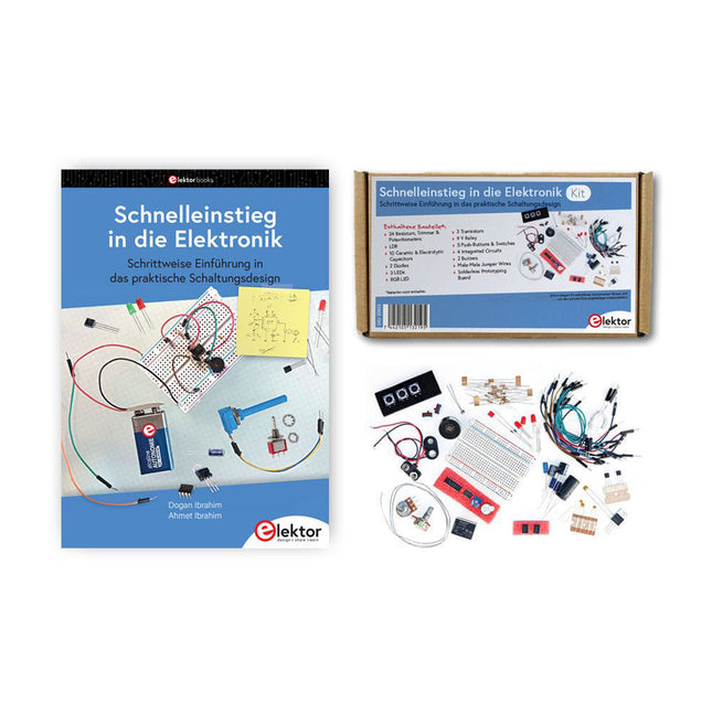
Elektor Bundles Schnelleinstieg in die Elektronik (Bundle)
Der Einstieg in die Elektronik ist einfacher, als Sie denken! Mit diesem Bundle – bestehend aus Buch und Experimentierkit – entdecken Sie die Grundlagen der Elektro- und Elektroniktechnik Schritt für Schritt. Anhand spannender Experimente lernen Sie praxisnah und verständlich, ganz ohne komplizierte Fachbegriffe oder langwierige Berechnungen. So sind Sie schon bald in der Lage, Ihre eigenen Elektronikprojekte umzusetzen! Das Kit enthält alle notwendigen Komponenten, um die meisten im Buch beschriebenen Schaltungen direkt auf dem Steckbrett aufzubauen und praktisch zu erproben. Das Kit kann selbstverständlich auch ohne das Buch zum Aufbau anderer Schaltkreise und zur Durchführung eigener Experimente verwendet werden. Inhalt des Kits 1x 39 Ω, 1 W Widerstand 1x 47 Ω Widerstand 1x 180 Ω Widerstand 1x 330 Ω Widerstand 3x 1 kΩ Widerstand 1x 2,2 kΩ Widerstand 1x 3,9 kΩ Widerstand 1x 6,8 kΩ Widerstand 1x 10 kΩ Widerstand 1x 15 kΩ Widerstand 1x 22 kΩ Widerstand 1x 33 kΩ Widerstand 1x 47 kΩ Widerstand 1x 56 kΩ Widerstand 1x 82 kΩ Widerstand 1x 120 kΩ Widerstand 1x 680 kΩ Widerstand 2x 100 kΩ Widerstand 1x 10 kΩ Trimmer 1x 10 kΩ Linearpotentiometer 1x 100 kΩ Linearpotentiometer 1x LDR 1x 1 nF Keramikkondensator 2x 10 nF Keramikkondensator 1x 100 nF Keramikkondensator 1x 1 µF, 25 V Aluminium-Elektrolytkondensator 2x 10 µF, 25 V Aluminium-Elektrolytkondensator 1x 100 µF, 25 V Aluminium-Elektrolytkondensator 1x 470 µF, 25 V Aluminium-Elektrolytkondensator 1x 1000 µF, 25 V Aluminium-Elektrolytkondensator 1x RGB-LED, Common-Cathode (CC) 1x 1N4148 Kleinsignaldiode 1x 1N4733A 5,1 V, 1 W Zenerdiode 3x LED, rot 2x BC337 NPN-Transistor 1x IRFZ44N N-Kanal-MOSFET 2x NE555-Timer 1x LM393-Komparator 1x 74HCT08 Quad-AND-Gatter 3x Tastschalter 2x SPDT-Schalter 1x Relais, SPDT, 9 VDC 1x Aktiver Summer 1x Passiver Summer 50 cm Massivdraht, 16 AWG, ohne Mantel 2x PP3 9 V Batterieclip 1x Steckbrett 20x Überbrückungskabel Dieses Bundle enthält: Buch: Schnelleinstieg in die Elektronik (Einzelpreis: 45 €) Kit: Schnelleinstieg in die Elektronik (Wert: 45 €)
€ 89,95€ 69,95Bestpreis
-
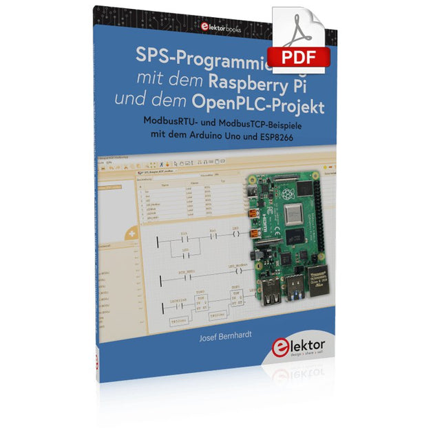
Elektor Digital SPS-Programmierung mit dem Raspberry Pi und dem OpenPLC-Projekt (PDF)
Einführung in die SPS-Programmierung mit dem Open-Source-Projekt auf dem Raspberry Pi und Modbus-Beispiele mit dem Arduino Uno und ESP8266 Die SPS-Programmierung ist heute in der Industrie und in der Hausautomation sehr weit verbreitet. In diesem Buch beschreibt der Autor, wie der Raspberry Pi 4 als SPS eingesetzt werden kann. Angefangen mit der Softwareinstallation auf dem Raspberry Pi und dem SPS-Editor auf dem PC geht es nach einer Beschreibung der Hardware an das Programmieren. Es folgen interessante Beispiele nach IEC 61131-3 in den verschiedenen Programmiersprachen. Ausführlich wird auch erklärt, wie der SPS-Editor benutzt wird und wie die Programme auf den Raspberry Pi geladen und ausgeführt werden. Angefangen mit der Programmierung mit KOP (Kontaktplan) über ST (Structured Control Language) bis zu AS (Special Function Chart) werden alle IEC-Sprachen mit Beispielen behandelt. Diese können auf der Website des Autors heruntergeladen werden. Auch die Vernetzung kommt nicht zu kurz. Der Arduino Uno und der ESP8266 werden als ModbusRTU- bzw. ModbusTCP-Module programmiert, um Zugriff auf externe Peripherie zu erhalten. Damit ist es möglich, Sensoren einzulesen und Verbraucher zu schalten. Interessant dürften auch E/A-Schaltungen sein, die dem 24V-Industriestandard entsprechen. Befehlsübersichten für ST und KOP runden das Buch ab. Nach dem Durcharbeiten des Buches ist der Leser in der Lage, eigene SPS-Steuerungen mit dem Raspberry Pi zu verwirklichen.
€ 32,80
Mitglieder: € 29,52
-
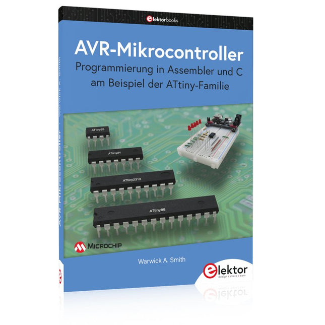
Elektor Publishing AVR-Mikrocontroller
Programmierung in Assembler und C am Beispiel der ATtiny-Familie Dieses Buch bietet einen eingehenden Blick auf die 8-Bit-AVR-Architektur in ATtiny- und ATmega-Mikrocontrollern, hauptsächlich aus der Sicht der Software und der Programmierung. Erforschen Sie die AVR-Architektur unter Verwendung von C und Assembler in Microchip Studio (früher Atmel Studio) mit ATtiny-Mikrocontrollern. Lernen Sie die Details der internen Funktionsweise von AVR-Mikrocontrollern kennen, einschließlich der internen Register und des Speicherplans von ATtiny-Bausteinen. Programmieren Sie Ihren ATtiny-Mikrocontroller mit einem Atmel-ICE-Programmiergerät/Debugger oder verwenden Sie ein preiswertes Hobby-Programmiergerät oder sogar einen Arduino Uno als Programmiergerät. Die meisten Code-Beispiele können mit dem Microchip Studio AVR-Simulator ausgeführt werden. Lernen Sie, Programme für ATtiny-Mikrocontroller in Assembler zu schreiben. Erfahren Sie, wie Assemblersprache in Maschinencodebefehle umgewandelt wird. Finden Sie heraus, wie Programme, die in der Programmiersprache C geschrieben wurden, in Assemblersprache und schließlich in Maschinencode umgewandelt werden. Verwenden Sie den Microchip Studio Debugger in Kombination mit einem Hardware-USB-Programmierer/Debugger, um Assembler- und C-Programme zu testen oder verwenden Sie den Microchip Studio AVR-Simulator. ATtiny-Mikrocontroller im DIP-Gehäuse werden verwendet, um eine einfache Nutzung auf Breadboards zu ermöglichen. Erfahren Sie mehr über Timing und Taktimpuls in AVR-Mikrocontrollern mit ATtiny-Bausteinen. Werden Sie zu einem AVR-Experten mit fortgeschrittenen Debugging- und Programmierfähigkeiten.
€ 39,80
Bestpreis
-
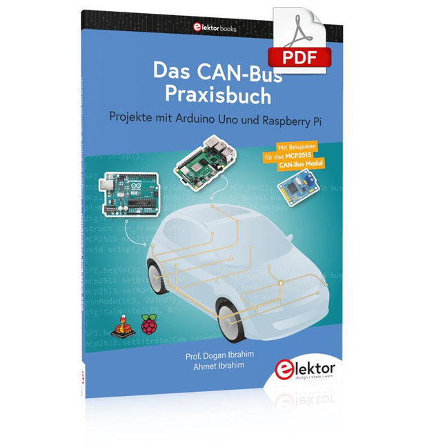
Elektor Digital Das CAN-Bus Praxisbuch (PDF)
Projekte mit Arduino Uno und Raspberry Pi In diesem Buch werden Anwendungen von Arduino Uno und Raspberry Pi 4 in praxisnahen Projekten auf Basis von CAN-Bus detailliert beschrieben. Durch den Einsatz von entweder Arduino Uno oder Raspberry Pi in Verbindung mit handelsüblichen CAN-Bus-Schnittstellenmodulen werden die Entwicklung, Fehlersuche und Fehlerbeseitigung sowie die Überprüfung von Projekten auf CAN-Bus-Basis erheblich erleichtert. Dieses Buch richtet sich an jeden, der mehr über den CAN-Bus lernen möchte und mit den Grundlagen der Elektronik vertraut ist. Hilfreich ist auch, Erfahrungen mit den Programmiersprachen C und Python sowie mit der Programmierung von Arduino Uno unter Verwendung seiner IDE und von Raspberry Pi zu haben. Das Buch ist eine nützliche Informationsquelle und ein Nachschlagewerk für jeden, der Antworten auf eine oder mehrere der folgenden Fragen sucht: Welche Bussysteme stehen für die Automobilindustrie zur Verfügung? Was sind die Grundprinzipien des CAN-Bus? Welche Arten von Frames (oder Datenpaketen) stehen in einem CAN-Bussystem zur Verfügung? Wie können Fehler in einem CAN-Bussystem erkannt werden, und wie zuverlässig ist ein CAN-Bussystem? Welche Arten von CAN-Bus-Controllern gibt es? Was sind die Funktionsprinzipien des MCP2515 CAN-Bus-Controllers? Wie kann ich ein CAN-Bus-Projekt mit Arduino Uno realisieren? Wie kann ich Arduino- oder Raspberry Pi-CAN-Bus-Projekte mit 2 und 3 Knoten erstellen? Wie kann ich die Daten auf dem CAN-Bus analysieren? Wie kann ich ein CAN-Bus-Projekt mit Raspberry Pi ausführen?
€ 29,80
Mitglieder: € 26,82
-

Elektor Digital Coding Modbus TCP/IP for Arduino (E-book)
Example projects with Node-RED, MQTT, WinCC SCADA, Blynk, and ThingSpeak This comprehensive guide unlocks the power of Modbus TCP/IP communication with Arduino. From the basics of the Modbus protocol right up to full implementation in Arduino projects, the book walks you through the complete process with lucid explanations and practical examples. Learn how to set up Modbus TCP/IP communication with Arduino for seamless data exchange between devices over a network. Explore different Modbus functions and master reading and writing registers to control your devices remotely. Create Modbus client and server applications to integrate into your Arduino projects, boosting their connectivity and automation level. With detailed code snippets and illustrations, this guide is perfect for beginners and experienced Arduino enthusiasts alike. Whether you‘re a hobbyist looking to expand your skills or a professional seeking to implement Modbus TCP/IP communication in your projects, this book provides all the knowledge you need to harness the full potential of Modbus with Arduino. Projects covered in the book: TCP/IP communication between two Arduino Uno boards Modbus TCP/IP communication within the Node-RED environment Combining Arduino, Node-RED, and Blynk IoT cloud Interfacing Modbus TCP/IP with WinCC SCADA to control sensors Using MQTT protocol with Ethernet/ESP8266 Connecting to ThingSpeak IoT cloud using Ethernet/ESP8266
€ 32,95
Mitglieder: € 29,66
-

Elektor Digital Kickstart to Arduino Nano (E-book)
Get Cracking with the Arduino Nano V3, Nano Every, and Nano 33 IoT The seven chapters in this book serve as the first step for novices and microcontroller enthusiasts wishing to make a head start in Arduino programming. The first chapter introduces the Arduino platform, ecosystem, and existing varieties of Arduino Nano boards. It also teaches how to install various tools needed to get started with Arduino Programming. The second chapter kicks off with electronic circuit building and programming around your Arduino. The third chapter explores various buses and analog inputs. In the fourth chapter, you get acquainted with the concept of pulse width modulation (PWM) and working with unipolar stepper motors. In the fifth chapter, you are sure to learn about creating beautiful graphics and basic but useful animation with the aid of an external display. The sixth chapter introduces the readers to the concept of I/O devices such as sensors and the piezo buzzer, exploring their methods of interfacing and programming with the Arduino Nano. The last chapter explores another member of Arduino Nano family, Arduino Nano 33 IoT with its highly interesting capabilities. This chapter employs and deepens many concepts learned from previous chapters to create interesting applications for the vast world of the Internet of Things. The entire book follows a step-by-step approach to explain concepts and the operation of things. Each concept is invariably followed by a to-the-point circuit diagram and code examples. Next come detailed explanations of the syntax and the logic used. By closely following the concepts, you will become comfortable with circuit building, Arduino programming, the workings of the code examples, and the circuit diagrams presented. The book also has plenty of references to external resources wherever needed. An archive file (.zip) comprising the software examples and Fritzing-style circuit diagrams discussed in the book may be downloaded free of charge below.
€ 29,95
Mitglieder: € 26,96
-

Elektor Digital PID-based Practical Digital Control with Raspberry Pi and Arduino Uno (E-book)
The Arduino Uno is an open-source microcontroller development system encompassing hardware, an Integrated Development Environment (IDE), and a vast number of libraries. It is supported by an enormous community of programmers, electronic engineers, enthusiasts, and academics. The libraries in particular really smooth Arduino programming and reduce programming time. What’s more, the libraries greatly facilitate testing your programs since most come fully tested and working. The Raspberry Pi 4 can be used in many applications such as audio and video media devices. It also works in industrial controllers, robotics, games, and in many domestic and commercial applications. The Raspberry Pi 4 also offers Wi-Fi and Bluetooth capability which makes it great for remote and Internet-based control and monitoring applications. This book is about using both the Raspberry Pi 4 and the Arduino Uno in PID-based automatic control applications. The book starts with basic theory of the control systems and feedback control. Working and tested projects are given for controlling real-life systems using PID controllers. The open-loop step time response, tuning the PID parameters, and the closed-loop time response of the developed systems are discussed together with the block diagrams, circuit diagrams, PID controller algorithms, and the full program listings for both the Raspberry Pi and the Arduino Uno. The projects given in the book aim to teach the theory and applications of PID controllers and can be modified easily as desired for other applications. The projects given for the Raspberry Pi 4 should work with all other models of Raspberry Pi family. The book covers the following topics: Open-loop and closed-loop control systems Analog and digital sensors Transfer functions and continuous-time systems First-order and second-order system time responses Discrete-time digital systems Continuous-time PID controllers Discrete-time PID controllers ON-OFF temperature control with Raspberry Pi and Arduino Uno PID-based temperature control with Raspberry Pi and Arduino Uno PID-based DC motor control with Raspberry Pi and Arduino Uno PID-based water level control with Raspberry Pi and Arduino Uno PID-based LED-LDR brightness control with Raspberry Pi and Arduino Uno
€ 32,95
Mitglieder: € 29,66
-

Elektor Digital The CAN Bus Companion (E-book)
Projects with Arduino Uno & Raspberry Pi with Examples for the MCP2515 CAN Bus Interface Module This book details the use of the Arduino Uno and the Raspberry Pi 4 in practical CAN bus based projects. Using either the Arduino Uno or the Raspberry Pi with off-the-shelf CAN bus interface modules considerably ease developing, debugging, and testing CAN bus based projects. This book is written for students, practicing engineers, enthusiasts, and for everyone else wanting to learn more about the CAN bus and its applications. The book assumes that the reader has some knowledge of basic electronics. Knowledge of the C and Python programming languages and programming the Arduino Uno using its IDE and Raspberry Pi will be useful, especially if the reader intends to develop microcontroller-based projects using the CAN bus. The book should be a useful source of reference material for anyone interested in finding answers to questions such as: What bus systems are available for the automotive industry? What are the principles of the CAN bus? How can I create a physical CAN bus? What types of frames (or data packets) are available in a CAN bus system? How can errors be detected in a CAN bus system and how dependable is a CAN bus system? What types of CAN bus controllers exist? How do I use the MCP2515 CAN bus controller? How do I create 2-node Arduino Uno-based CAN bus projects? How do I create 3-node Arduino Uno-based CAN bus projects? How do I set the acceptance masks and acceptance filters? How do I analyze data on the CAN bus? How do I create 2-node Raspberry Pi-based CAN bus projects? How do I create 3-node Raspberry Pi-based CAN bus projects?
€ 32,95
Mitglieder: € 29,66
-

Elektor Digital Controller Area Network Projects with ARM and Arduino (E-book)
This book details the use of the ARM Cortex-M family of processors and the Arduino Uno in practical CAN bus based projects. Inside, it gives a detailed introduction to the architecture of the Cortex-M family whilst providing examples of popular hardware and software development kits. Using these kits helps to simplify the embedded design cycle considerably and makes it easier to develop, debug, and test a CAN bus based project. The architecture of the highly popular ARM Cortex-M processor STM32F407VGT6 is described at a high level by considering its various modules. In addition, the use of the mikroC Pro for ARM and Arduino Uno CAN bus library of functions are described in detail. This book is written for students, for practising engineers, for hobbyists, and for everyone else who may need to learn more about the CAN bus and its applications. The book assumes that the reader has some knowledge of basic electronics. Knowledge of the C programming language will be useful in later chapters of the book, and familiarity with at least one microcontroller will be an advantage, especially if the reader intends to develop microcontroller based projects using CAN bus. The book should be useful source of reference to anyone interested in finding an answer to one or more of the following questions: What bus systems are available for the automotive industry? What are the principles of the CAN bus? What types of frames (or data packets) are available in a CAN bus system? How can errors be detected in a CAN bus system and how reliable is a CAN bus system? What types of CAN bus controllers are there? What are the advantages of the ARM Cortex-M microcontrollers? How can one create a CAN bus project using an ARM microcontroller? How can one create a CAN bus project using an Arduino microcontroller? How can one monitor data on the CAN bus?
€ 32,95
Mitglieder: € 29,66
-

Elektor Labs Elektor Rauscharmes Labornetzteil
Das rauscharme Labornetzteil von Elektor ist ein vollständig analoges, einstellbares, symmetrisches Gerät mittlerer Leistung, das ohne Schalt- oder digitale Komponenten auskommt. Es bietet eine Ausgangsspannung, die zwischen 0 V und ±22 V einstellbar ist, sowie einen Ausgangsstrom, der von 0 A bis 1 A eingestellt werden kann. Da auf jegliche Art von Schalttechnik verzichtet wird, liefert das Design extrem geringes Rauschen. Zur Anzeige beider Ausgangsspannungen und -ströme werden vier kleine analoge Einbauinstrumente mit Drehspulmesswerk verwendet. Die meisten modernen Labornetzgeräte und AC-Adapter arbeiten mit Schaltnetzteiltechnik. Selbst die besten Ausführungen weisen zwangsläufig hochfrequente Restwelligkeit und andere Schaltartefakte am Ausgang auf, die die Prüfung empfindlicher analoger Schaltungen stören und Messungen kleiner Signale beeinträchtigen können. Um dieses Problem zu vermeiden, setzt dieses Konzept auf ein vollständig analoges Netzgerät. Obwohl es weniger effizient ist als vergleichbare Schaltnetzteile, spielt die geringere Effizienz beim Einsatz auf dem Prüfstand kaum eine Rolle und sorgt für sauberere und zuverlässigere Messergebnisse. Da viele analoge Schaltungen eine symmetrische Versorgung benötigen, liefert dieses Design positive und negative Ausgangsspannungen gleicher Höhe. Eine geringfügige Nachjustierung ist möglich, um eventuelle Ungleichgewichte auszugleichen. Selbstverständlich ist auch eine einstellbare Strombegrenzung integriert. Das Kit enthält die für den Aufbau des Netzteils erforderlichen Komponenten, mit Ausnahme der Transformatoren. Technische Daten Ausgangsspannung 0…+22 V, 0, −22 V Ausgangsstrom 0…+1 A, 0…−1 A Rauschen −85 dBV (bei 0,95 A/20 V, B = 22 kHz) −84 dBV (bei 0,95 A/20 V, B > 500 kHz) Restwelligkeit 50 µVRMS (bei 950 mA/20 V, B = 22 kHz, hauptsächlich 100-Hz-Anteil) Lieferumfang 3x Platinen: Regler (PCB-1), Netzfilter (PCB-2) und Transformator (PCB-3) Alle Bauteile mit Ausnahme der Netztransformatoren 4x Drehspulmesswerke Zusätzliche Teile für die Verdrahtung (Drähte, Bananenbuchsen, Kaltgeräte-Netzmodul usw.) Nicht enthalten Die drei Netztransformatoren Ein Gehäuse Stückliste Für die Spannungsregler-Platine (240386-1) Widerstände (250 mW, 1%) R1 = 12 Ω R2, R8, R37, R62 = 1 MΩ R3, R7, R10, R13, R17, R20, R22, R30, R35, R42, R45, R47, R55, R60 = 100 Ω, 600 mW R4, R5 = 4.7 kΩ R6 = 100 kΩ R9, R12, R14, R36, R38, R39, R61, R63, R66, R72, R78, R79 = 10.0 kΩ, 600 mW R11 = 9.76 kΩ, 600 mW R15, R40 = 44.2 kΩ, 600 mW R16, R41, R77 = 1 kΩ R18, R43 = 1.5 kΩ, 1 W, 5% R19, R44 = 470 Ω, 1 W, 5% R21, R46 = 330 Ω, 600 mW R23, R24, R48, R49 = 1.0 Ω, 1 W R25, R50 = 1 kΩ, 1 W, 5% R26, R28, R51, R53 = 1.000 kΩ 0.1%, 15 ppm/C R27, R29, R52, R54 = 10.00 kΩ 0.1%, 15 ppm/C R31, R56 = 1.2 kΩ, 1 W, 5% R32, R57 = 47 kΩ R33, R58 = 270 Ω R34, R59 = 27 kΩ R64, R69 = 12.0 kΩ R65 = 3.0 kΩ, 600 mW R67, R80 = 470 Ω, 600 mW R68, R70 = 6.8 kΩ, 600 mW R71 = 30.0 kΩ,, 600 mW R73, R74, R75, R76 = 10 MΩ P1, P2, P3 = 10 kΩ, 200 mW, 20%, potentiometer, 1 turns, single, lin., panel mount P4, P5 = 500 Ω, 500 mW, 10%, trimmer, 25 turns, 3296Y-1-501LF Bourns P6, P7 = 10 kΩ, 500 mW, 10%, trimmer, 25 turns, 3296Y-1-501LF Bourns Kondensatoren C1 = 100 nF, 50 V, 10%, ceramic X7R, LS 5 mm C2, C3, C6, C7, C30 = 10 µF, 63V, 20%, LS 2.5 mm, 3000hours@105°C C4, C5, C8, C9, C13, C14, C18, C19, C23, C24, C28, C29, C31, C32, C38, C39 = 100 nF, 250 V, 10%, PET, LS 7.5 mm C10, C20 = 47 nF, 100 V, 5%, PET, LS 5 mm C11, C21 = 10 nF, 100 V, 5%, PET, LS 5 mm C12, C22 = 220 µF, 35 V, 20%, 0.024 Ω, LS2.5/3.5 mm, Ir 3.4 A, 2000hours@125°C, polymer C15, C25 = 120 µF, 50 V, 20%, ESR 0.02 Ω, Diam. 10 mm max., LS 5 mm C16, C26 = 15 nF, 100 V, 5%, PET, LS 5 mm C17, C27 = 47 nF, 100 V, 5%, PET, LS 5 mm C33, C34 = 22 µF, 50 V, 20%, LS 2 mm, 10000 hours @ 105°C C35, C36, C44, C45 = 1 µF, 100 V, 10%, LS 5 mm, ceramic X7R C37 = 100 uF, 50 V, 20%. LS 3.5 mm C40, C41, C42, C43, C46, C47, C48, C49 = 1000 µF, 50 V, 20%, LS 5/7.5 mm, Ir 3.32 A, 10000hours@105°C, D 16 mm C50, C51, C52, C53 = 47 nF, 100 V, 10%, ceramic X7R, LS 5 mm Induktivitäten L1, L2 = 4.7 µH, 3.2 A, 0.033 Ω, LS 5 mm, RLB0914-4R7ML Bourns L3 = Commom mode choke, 14.5 mH, 3 A, SSRH24NH-30145 Kemet Halbleiter D1, D2, D3, D4, D5, D9, D10, D11, D15 = BAT85, DO-34 D6, D7, D12, D13 = SR560, DO-201AD D8, D14, D16 = 1N4148, DO-35 D17 = Zenerdiode, 5.6 V, 0.5 W, DO-41 D18, D19 = 1N4004, DO-41 D20, D21 D22, D23 = V30100CI-M3/P, dual common cathode, TO-220 D24 = Zener diode, 30 V, 1 W, DO-41 LED1, LED2 = LED, red, T-1 (3 mm) LED3, LED4 = LED, green, T-1 (3 mm) TVS1, TVS2 = BZW50-33B, R6 T1, T2, T4 = BC337.25, TO-92 T3 = NJW0302G, TO-3P T5, T6, T8 = BC327.25, TO-92 T7 = NJW0281G, TO-3P T9 = BD139, TO-126 (SOT-32) IC1 = LM334Z, TO-92 IC2 = LM4040AIZ-5.0/NOPB, TO-92 (TO-226AA-3) IC3, IC4 = OPA2992IDR, SOIC-8 IC5, IC6 = OPA4992IDR, SOIC-14 IC7 = OPA992IDBVR, SOT-23-5 IC8 = LM339N, DIP-14 IC9 = LM317, TO-220 IC10 = LM337, TO-220 Sonstiges F1, F2 = 5×20 mm fuse, 1.6 A, fast acting HS1, HS2 = Heatsink MC33271 (for T3/T7), 2.7°C/W, PCB mount, height 63.5 mm K1, K4 = 3-way screw terminal block, LS 3.5 mm, max. 1.5 mm² K2, K3 = 3-way screw terminal block, LS 3.5 mm, max. 1 mm² M1, M3 = Moving coil meter, Range 30 V, type 91C4, 45×45 mm M2, M4 = Moving coil meter, Range 1 A, type 91C4, 45×45 mm² RE1 = Relay DPDT,5V, UA2-5NU Verschiedenes 3× 3-way screw terminal block, LS 3.5 mm, max. 1 mm² (for P1, P2, P3) 4× Pin header, 1×2, vertical, pitch 2.54 mm (for LED1, LED2, LED3, LED4) 4× Pin socket, 1×2, vertical. pitch 2.54 mm (for LED1, LED2, LED3, LED4) 2× Heatsink FK222SA220, 20°C/W, PCB mount (for IC9 & IC10) 2× Mica thermal pad for TO-220, 12×18×0.05 mm (for IC9 & IC10) 2× Insulating bushing IB 6, TO-220 (for IC9 & IC10) 2× Ceramic thermal pad, 23×20×2 mm (for T3 & T7) 2× PCB Fuse Holder, for 5×20 mm fuse, 10 A (for F1, F2) 2× Cover for PCB Fuse Holder, transparent (for F1, F2) 2× 2-way screw terminal block, LS 3.5 mm, max. 1 mm² (for M1 & M3) 2× 2-way screw terminal block, LS 3.5 mm, max. 1.5 mm² (for M2 & M4) 8× M3 solder lug, thickness 0.35 mm (for M1…M4) M4 solder lug, thickness 0.35 mm (to connect 4 mm banana connectors) Screened cable, 1 pair, 2×24 AWG/0.22 mm², 1 m (for P1, P2 & P3) IC socket, DIP, 14 contacts (for IC8) M3 washer, plain, steel M3 screw, 16 mm, steel, pan head M3 nut M3 spring washer 50 mm M3 standoff, steel, male-female 12 mm M3 standoff, steel, male-female 10 mm M3 standoff, steel, male-female M3 screw, 8 mm, steel, pan head Für die Netzfilter-Platine (240386-2) Widerstand R1 = 220 kΩ, 1 W, 500 V, 5% Kondensatoren C1, C2 = 470 nF, 305 VAC, Class X2, 11 × 27 mm max., LS 15/22.5 mm C3, C4, C5, C6 = 2.2 nF, 300 VAC, Class Y2, 13 × 4 mm, LS 10 mm, PP Induktivitäten L1, L2 = Common-mode choke, 6.8 mH, 1.7 A, TDK B82732R2172B030 Halbleiter MOV1 = TVS varistor, 300 VAC, S14K300 (230 VAC, B72214S0301K101) and SK14K150 (150 VAC, B72214S0151K101) Sonstiges K1, K2 = 3-way screw terminal block, LS 7.62 mm F1 = Time-delay fuse, 0.5 A (230 VAC) or 1 A (115 VAC) Verschiedenes 1× Fuse holder, 5×20 mm, 10 A, 500 VAC 1× Transparent fuse cover 4× 10 mm M3 standoff, steel, male–female 4× M3 screw, 8 mm, steel, pan head 4× M3 nut Für die Transformator-Platine (240386-3) Widerstände R1, R2 = 2.7 kΩ, 600 mW, 1% R3 = 10.0 kΩ, 600 mW, 1% Kondensator C1 = 220 µF, 50 V, 20%, Ø10 mm, LS 5 mm, 4000 h @ 105°C Transformatoren (nicht im Lieferumfang dieses Kits enthalten!) TR1, TR2, TR3 = 2×7 V, 25 VA, PCB-mounted toroid, 70060K Talema Halbleiter D1–D4 = 1N4148, DO-35 D5, D6 = 1N4004, DO-41 D7 = Zener 5.6 V, 1.3 W, DO-41 LED1 = LED, red, T-1 (3 mm) IC1, IC2 = MOC8021M, CTR ≥ 1000%, DIP-6 Sonstiges F1, F2, F3 = 160 mA time-delay fuse (230 VAC) or 315 mA time-delay fuse (115 VAC) K1 = 2-way screw terminal block, LS 7.62 mm K2 = 3-way screw terminal block, LS 3.5 mm, max 1.5 mm² K3, K4 = 3-way screw terminal block, LS 3.5 mm, max 1 mm² RE1, RE2 = Relay DPDT, 5 A/250 VAC / 24 VDC Verschiedenes 1× Pin header 1×2, pitch 2.54 mm + matching socket for LED1 3× Fuse holder 5 × 20 mm, 10 A, 500 VAC + transparent cover 3× M4 screw, 8 mm, pan head + washer for TR1-TR3 8× M3 screw, 8 mm, pan head + nut + washer 8× 10 mm M3 standoff, steel, male–female 2× IC socket, DIP-6 for IC1 & IC2 Weitere Bauteile 1 m red insulated wire, stranded, 1.5 mm² 0.5 m blue insulated wire, stranded, 1.5 mm² 0.5 m black insulated wire, stranded, 1.5 mm², 0.5 m 2 m red insulated wire, stranded, D 0.56 mm (0.25 mm²) 2 m black insulated wire, stranded, D 0.56 mm (0.25 mm²) 0.5 m Multicore Cable, Flexible, 3 Core, 0.75 mm² (24 x 0.2 mm) Red banana socket Black banana socket Blue banana socket Green banana socket IEC Power Entry Module with switch, IEC C14 3 crimp terminals, FASTON, 4.75 x 0.81 mm 3 knobs Links Elektor Labs JumpStarter Page Artikel (Teil 1) Artikel (Teil 2)
€ 299,00€ 249,00Bestpreis
-
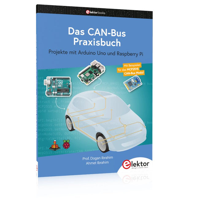
Elektor Publishing Das CAN-Bus Praxisbuch
Projekte mit Arduino Uno und Raspberry Pi In diesem Buch werden Anwendungen von Arduino Uno und Raspberry Pi 4 in praxisnahen Projekten auf Basis von CAN-Bus detailliert beschrieben. Durch den Einsatz von entweder Arduino Uno oder Raspberry Pi in Verbindung mit handelsüblichen CAN-Bus-Schnittstellenmodulen werden die Entwicklung, Fehlersuche und Fehlerbeseitigung sowie die Überprüfung von Projekten auf CAN-Bus-Basis erheblich erleichtert. Dieses Buch richtet sich an jeden, der mehr über den CAN-Bus lernen möchte und mit den Grundlagen der Elektronik vertraut ist. Hilfreich ist auch Erfahrung mit den Programmiersprachen C und Python sowie mit der Programmierung von Arduino Uno unter Verwendung seiner IDE und von Raspberry Pi zu haben. Das Buch ist eine nützliche Informationsquelle und ein Nachschlagewerk für jeden, der Antworten auf eine oder mehrere der folgenden Fragen sucht: Welche Bussysteme stehen für die Automobilindustrie zur Verfügung? Was sind die Grundprinzipien des CAN-Bus? Welche Arten von Frames (oder Datenpaketen) stehen in einem CAN-Bussystem zur Verfügung? Wie können Fehler in einem CAN-Bussystem erkannt werden, und wie zuverlässig ist ein CAN-Bussystem? Welche Arten von CAN-Bus-Controllern gibt es? Welches sind die Funktionsprinzipien des MCP2515 CAN-Bus-Controllers? Wie kann ich ein CAN-Bus-Projekt mit Arduino Uno realisieren? Wie kann ich Arduino oder Raspberry Pi CAN-Bus-Projekte mit 2 und 3 Knoten erstellen? Wie kann ich die Daten auf dem CAN-Bus analysieren? Wie kann ich ein CAN-Bus-Projekt mit Raspberry Pi ausführen?
€ 34,80
Bestpreis


