
Suchergebnisse für "siglent OR oscilloscope OR sds1102x"
-

Siglent Siglent SPD3303X 3-Kanal DC-Netzteil (220 W)
Bei der SPD3000X-Serie handelt es sich um lineare und programmierbare Labornetzteile mit 4,3’’-TFT-LCD. Seine Programmierbarkeit und sein Echtzeit-Display bieten einen besonderen Bedienkomfort. Die Netzteile verfügen über drei isolierte Ausgänge: zwei für kontinuierlich einstellbare und einer für umschaltbare Spannungen von 2,5, 3,3 und 5,0 V. Die Ausgänge sind zudem gegen Kurzschluss und Überlastung geschützt. Die Labornetzteile eignen sich für den Einsatz in der Entwicklung und in der Produktion. Features 3 unabhängige und isolierte Ausgänge, 2 x 0...32 V / 3,2 A, 1 x 2,5/3,3/5,0 V / 3,2 A Gesamtleistung: maximal 220 W Anzeige: Spannung 4 Digits, Strom 3 Digits, Auflösung: min. 1 mV, 1 mA Unterstützt zeitgesteuerte Ausgangsfunktionen 4,3’’-Farb-TFT-LCD mit einer Auflösung von 480 x 272 Pixel 3 Betriebsmodi: unabhängig, seriell und parallel Netzspannung 100/120/220/230 für den Betrieb an unterschiedlichen Netzen Intelligenter temperaturgesteuerter Lüfter für geringes Betriebsgeräusch Klares grafisches Interface mit Anzeigemöglichkeit für Kurvenformen Interne Speichermöglichkeit für 5 Sätze an System-Parametern Unterstützt Erweiterung des Datenspeichers Im Lieferumfang: PC-Software Easypower, Unterstützung für SCPI, LabVIEW-Treiber Hochauflösender und präziser Ausgang Die hohe Auflösung von 1 mV/1 mA erleichtert die genaue Einstellung und die leichte Ablesbarkeit der Werte. Die Elektronik garantiert minimalste Abweichungen bei Spannung und Strom. Funktionen für unabhängigen, seriellen und parallelen Betrieb Die drei Ausgänge können dank Isolation völlig unabhängig voneinander genutzt werden. Darüber hinaus können zwei Ausgänge für mehr Spannung in Serie oder für mehr Strom parallelgeschaltet werden, was den Einsatzbereich des Labornetzteils deutlich erweitert. Weiter kann jeder der drei Ausgänge individuell oder auch gemeinsam ein- und ausgeschaltet werden. Anzeige des zeitlichen Verlaufs Es können fünf Gruppen für das Timing bzw. die Ausgangssteuerung angezeigt werden, was eine einfache Programmiermöglichkeit der Verläufe ergibt. Das Labornetzteil kann auch mit der PC-Software EasyPower von Siglent gesteuert werden, was die Möglichkeiten nochmals erweitert. Speicherung von Parametern Die programmierbare SPD3000X-Labornetzteil-Serie ist dazu in der Lage, bis zu 5 Parameter-Gruppen im internen Speicher abzulegen und wieder aufzurufen. Zudem wird eine Speichererweiterung unterstützt. Auf diese Weise hat man jederzeit die benötigten Einstellungen per Knopfdruck zur Verfügung.
€ 600,50
Bestpreis
-
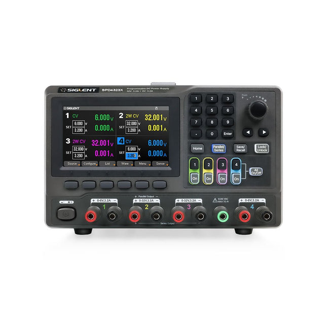
Siglent Siglent SPD4323X 4-Kanal Netzteil (240 W)
The Siglent SPD4323X is a 4-channel DC Linear Programmable Power Supply equipped with a 4.3-inch TFT-LCD display, friendly human-machine interface, and excellent performance indicators. Real-time waveform display provides engineers with an informative user interface. SPD4323X offers a total output power of 240 W with a resolution of 1 mV/1 mA. The maximum voltage and current for each channel are as follows: CH1: 6 V/3.2 A CH2: 32 V/3.2 A CH3: 32 V/3.2 A CH4: 6 V/3.2 A Features Rated output power: 240 W Rated voltage: 32 V, 12 V, 30 V Up to four high-precision power supplies with independent controllable outputs, supporting CH2 and CH3 series and parallel connections Clear graphical interface with waveform and timer display modes 5-digit voltage and current display with minimum resolution of 1 mV, 1 mA Fast output response time: <50us The high current channel support remote voltage compensation sense function. The maximum compensation voltage is 0.6 V Overvoltage protection and overcurrent protection or safe and accurate operation Equipped with a 4.3-inch TFT-LCD display (480 x 272 resolution) USB and LAN standard communication USB-GPIB module is optional Excellent channel density with up to 4 channels in a 3U half rack package Internal data storage for setups and parameters Embedded Web Server with instrument communication that doesn’t require software installation Fully SCPI programming command set support as well as a LabView driver for remote control and system automation Technische Daten SPD4323X SPD4121X SPD4306X Channel Output CH1: Voltage 0 to 6 V Current 0 to 3.2 ACH2: Voltage 0 to 32 V Current 0 to 3.2 ACH3: Voltage 0 to 32 V Current 0 to 3.2 ACH4: Voltage 0 to 6 V Current 0 to 3.2 A CH1: Voltage 0 to 15 V Current 0 to 1.5 ACH2: Voltage 0 to 12 V Current 0 to 10 ACH3: Voltage 0 to 12 V Current 0 to 10 ACH4: Voltage 0 to 15 V Current 0 to 1.5 A CH1: Voltage 0 to 15 V Current 0 to 1.5 ACH2: Voltage 0 to 30 V Current 0 to 6 ACH3: Voltage 0 to 30 V Current 0 to 6 ACH4: Voltage 0 to 15 V Current 0 to 1 A Resolution 1 mV, 1 mA 1 mV, 1 mA 1 mV, 1 mA Setting Accuracy Voltage: ±(0.03% of reading+10) mV, Current: ±(0.3% of reading+10) mA Voltage: ±(0.03% of reading+10) mV, Current: ±(0.3% of reading+10) mA Voltage: ±(0.03% of reading+10) mV, Current: ±(0.3% of reading+10) mA Readback Accuracy Voltage: ±(0.03% of reading+10) mV, Current: ±(0.3% of reading+10) mA Voltage: ±(0.03% of reading+10) mV, Current: ±(0.3% of reading+10) mA Voltage: ±(0.03% of reading+10) mV, Current: ±(0.3% of reading+10) mA Display 4.3" TFT-LCD 5-digit voltage and current display 4.3" TFT-LCD 5-digit voltage and current display 4.3" TFT-LCD 5-digit voltage and current display Output power 240 W 285 W 400 W Lieferumfang 1x Siglent SPD4323X Power Supply 1x Power cord (EU) 1x Output test cord (3 A) 1x USB cable 1x Quick start guide Downloads Datasheet Manual Quick start
€ 762,30
Bestpreis
-

FNIRSI FNIRSI SG-003A Signalgenerator
Der FNIRSI SG-003A ist ein kleiner, hochpräziser Signalgenerator mit einem 2,4' TFT-Farbdisplay mit einem Frequenzbereich von bis zu 10 kHz und einem aktiven und passiven Stromausgang von 24 mA. Die maximale Ausgangsspannung beträgt 24 V. Die eingebaute 3000-mAh-Lithiumbatterie hat eine Laufzeit von 10 Stunden. FNIRSI SG-003A wird hauptsächlich für die Fehlersuche in industriellen SPS, Prozessinstrumenten, elektrischen Ventilen usw. verwendet. Features Genauigkeit (Spannung/Strom) 0,1% ±0,005 Auflösung (aktuell) 0,01 mA Frequenz 0-10 kHz Auflösung 5 Ziffern Ausgangsleistung 24 V Display 2,4" TFT-LCD (320 x 240) Abmessungen 92 x 72 x 30 mm Gewicht 165 g Technische Daten Signal Bereich Genauigkeit Auflösung Maximale Belastung Externe Stromversorgung Aktiver Stromausgang 0~24 mA ±(0,1% + 0,005) 0,01 mA 750 Ω Passiver Stromausgang (XMT) 0~24 mA ±(0,1% + 0,005) 0,01 mA 0~30 V Spannungsausgang 0~24 V ±(0,1% + 0,005) 0,01 V 24-V-Schleife 0~24 mA ±(0,1% + 0,005) 0,01 mA Frequenzausgang 0~9999 Hz ±2% 5 Ziffern Stromeingang 0~24 mA ±(0,1% + 0,005) 0,01 mA Spannungseingang 0~30 V ±(0,1% + 0,005) 0,01 V Lieferumfang 1x FNIRSI SG-003A Signalgenerator 4x Testclips 1x USB-Ladegerät 1x USB-C Kabel 1x Manual Downloads Manual Firmware V4.3
€ 68,79
-

Siglent Siglent SPD4306X 4-Kanal Netzteil (400 W)
The Siglent SPD4306X is a 4-channel DC Linear Programmable Power Supply equipped with a 4.3-inch TFT-LCD display, friendly human-machine interface, and excellent performance indicators. Real-time waveform display provides engineers with an informative user interface. SPD4306X offers a total output power of 400 W with a resolution of 1 mV/1 mA. The maximum voltage and current for each channel are as follows: CH1: 15 V/1.5 A CH2: 30 V/6 A CH3: 30 V/6 A CH4: 15 V/1 A Features Rated output power: 400 W Rated voltage: 32 V, 12 V, 30 V Up to four high-precision power supplies with independent controllable outputs, supporting CH2 and CH3 series and parallel connections Clear graphical interface with waveform and timer display modes 5-digit voltage and current display with minimum resolution of 1 mV, 1 mA Fast output response time: <50us The high current channel support remote voltage compensation sense function. The maximum compensation voltage is 0.6 V Overvoltage protection and overcurrent protection or safe and accurate operation Equipped with a 4.3-inch TFT-LCD display (480 x 272 resolution) USB and LAN standard communication USB-GPIB module is optional Excellent channel density with up to 4 channels in a 3U half rack package Internal data storage for setups and parameters Embedded Web Server with instrument communication that doesn’t require software installation Fully SCPI programming command set support as well as a LabView driver for remote control and system automation Technische Daten SPD4323X SPD4121X SPD4306X Channel Output CH1: Voltage 0 to 6 V Current 0 to 3.2 ACH2: Voltage 0 to 32 V Current 0 to 3.2 ACH3: Voltage 0 to 32 V Current 0 to 3.2 ACH4: Voltage 0 to 6 V Current 0 to 3.2 A CH1: Voltage 0 to 15 V Current 0 to 1.5 ACH2: Voltage 0 to 12 V Current 0 to 10 ACH3: Voltage 0 to 12 V Current 0 to 10 ACH4: Voltage 0 to 15 V Current 0 to 1.5 A CH1: Voltage 0 to 15 V Current 0 to 1.5 ACH2: Voltage 0 to 30 V Current 0 to 6 ACH3: Voltage 0 to 30 V Current 0 to 6 ACH4: Voltage 0 to 15 V Current 0 to 1 A Resolution 1 mV, 1 mA 1 mV, 1 mA 1 mV, 1 mA Setting Accuracy Voltage: ±(0.03% of reading+10) mV, Current: ±(0.3% of reading+10) mA Voltage: ±(0.03% of reading+10) mV, Current: ±(0.3% of reading+10) mA Voltage: ±(0.03% of reading+10) mV, Current: ±(0.3% of reading+10) mA Readback Accuracy Voltage: ±(0.03% of reading+10) mV, Current: ±(0.3% of reading+10) mA Voltage: ±(0.03% of reading+10) mV, Current: ±(0.3% of reading+10) mA Voltage: ±(0.03% of reading+10) mV, Current: ±(0.3% of reading+10) mA Display 4.3" TFT-LCD 5-digit voltage and current display 4.3" TFT-LCD 5-digit voltage and current display 4.3" TFT-LCD 5-digit voltage and current display Output power 240 W 285 W 400 W Lieferumfang 1x Siglent SPD4306X Power Supply 1x Power cord (EU) 1x Output test cord (3 A) 1x USB cable 1x Quick start guide Downloads Datasheet Manual Quick start
€ 1.101,10
Bestpreis
-

Elektor Digital Les oscilloscopes anciens & modernes pour les débutants (E-book)
Ce qui se passe en électronique est par définition invisible à l'oeil nu. L'instrument qui permet précisément de rendre visibles les signaux électriques, celui par le truchement duquel les effets de l'électronique se manifestent à nous, c'est l'oscilloscope. Hélas, quand on commence à faire de l'électronique, c'est souvent sans oscilloscope. Et l'on en est réduit à tâtonner, aussi bien physiquement que mentalement. Le jour où l'on goûte à la visualisation des signaux sur un écran, c'est une révélation. Plus personne ne souhaite se priver de cet enchantement. Pas de retour en arrière. En électronique, si l'on veut progresser dans le plaisir et dans la compréhension, il faut un oscillo. Commence alors une période d'interrogation : comment choisir ? Et à peine cette question-là aura-t-elle trouvé sa réponse, il en viendra une ribambelle d'autres que l'on peut résumer en une seule : comment se servir de l'oscilloscope de telle sorte que ce qu'il affiche corresponde bien à la réalité des signaux ? Dans ce livre, Rémy Mallard, répond clairement à ces questions. Il donne aussi de nombreuses informations pour aider son lecteur à élucider lui-même de nouveaux mystères qui ne manqueront pas de surgir. Ceux qui le connaissent déjà comme l'auteur d'un livre sur l'électronique dont le titre est un programme à lui tout seul : L'électronique pour les débutants qui sèchent les cours mais soudent sans se brûler les doigts, ainsi que d'un livre d'initiation à la programmation des microcontrôleurs PIC, savent qu'ils trouveront ici un ouvrage utile, qu'ils rouvriront souvent.
€ 34,95
Mitglieder: € 31,46
-

Elektor Digital Elektor November/December 2020 (PDF) EN
New LCR Meter 50 Hz - 2 MHz Part 1automatic impedance measuring bridge measures the resistance, capacitance and inductance of components with an impedance of 10 mΩ to 100 MΩ From Ding-Dong Door Chime to IoT DoorbellIntegrate your doorbell in Home Assistant with ESPHome Battery ManagementWhat to Be Aware of When Using (Lithium) Batteries Starting Out in ElectronicsEasier Than Imagined! Small Circuits RevivalFrom the Elektor Suggestions Box Breadboard Graphics with Fritzing Analogue Filter Design (Part 2)Active Filters Homelab Tours: The Lap CounterA Project for Mini Petrol-Heads Developer’s ZoneTips & Tricks, Best Practices and Other Useful Information Review: Rigol DS1054Z Four-Channel Oscilloscope Christmas CandleBlow It Out! Tunable Valve Sinewave Generator Retro is back! Review: The Rigol DG2072 Generator KiCad Plugins and Add-ons Differential Oscilloscope Current Probe 2.0Measure Currents Using Your Oscilloscope The Hewlett-Packard Interface LoopConnect the world! The Future of Machine LearningAn Interview with Daniel Situnayake Smartphone Apps for Android and iOSProgramming Apps Within a Single Development Environment From Life's ExperienceThe Value of a Technical Education 5G: How Infrastructure Shapes Our Society Practical ESP32 Multitasking (5)Task event notification HP 10811 OscillatorPeculiar Parts, the series LoRa GPS TrackerWith Open Hardware and Software Programming the Finite State Machinewith 8-bit PICs in Assembly and C
€ 7,50
-

Micsig Micsig CP2100A AC/DC-Stromzange
Features Bandwidth: DC-800 KHz Maximum measurable current: 100 Apk (70.7 Arms) Max. conductor diameter: 13 mm Auto & Manual "Zero" function Directly powered by USB port Standard BNC interface, compatible with any oscilloscope Technische Daten Bandwidth DC-800 KHz Rise time <= 583 ns Ranges 10 A / 100 A Output sensitivity 0.1 V/A (10 A) 0.01 V/A (100 A) DC accuracy 3% ±50 mA (10 A) 4% ±50 mA (100 A, 500 mA - 40 Apk) 15% (100 A, 40 Apk -100 Apk) Signal delay < 150 ns (10 A) < 200ns (100 A) Current measurement range 50 mA - 10 Apk (10 A) 1 A - 100 Apk (100 A) Max. Voltage CAT III 300 V CAT II 600 V Power supply DC 5 V Downloads Quick Guide Datasheet Manual
€ 304,64
-

Elektor Digital Elektor May/June 2026 (PDF) EN
Elektor GREEN and GOLD members can download their digital edition here. Not a member yet? Click here. PbMonitor v2.0 UpdateBattery Monitoring with Improved Analog Design Audio Latency MeasurementA Standalone Tool for Evaluating Errors and Latency in Audio Transmission Square Wave vs. Bode PlotChecking the Performances of an Audio Device embedded world 2026 Clever Coding with AIAI in Software Development for Electronics Engineers QA403 Audio AnalyzerAffordable Precision for Audio Professionals and Hobbyists EasyGimbalAutonomous Camera Tracking with AI, Stepper and Servo Motors Sigfox Breakout Board (2)Sending Messages Circuit ProtectionControlling Overvoltages with TVS Diodes Emerging Battery Testing ApproachesA New Era of Diagnostics AudiotronicsA First Preamplifier CANopenTermAn Open-Source Tool That Brings CAN to Makers and Engineers Alike Stabilization of Operational AmplifiersAvoiding Feedback Instability Err-lectronicsCorrections, Updates, and Readers’ Letters Signal ConditioningTips and Tricks to Fit Voltage Ranges TDR Attachment for OscilloscopesLength, Short Circuit, Mismatch: Measure Cables Using Reflections! From Life's ExperienceLED It Be Speaker Oscillator and Resonance TesterA Fully Experimental Project for Your Speakers Elektor Community Perspectives on Test and Measurement ESP32 Audio Transceiver Board (Part 5)Audio Processing and Remote Control 2026: An AI OdysseyAI Has a Context Problem Battery Storage for Balcony Power PlantsSmall Batteries, Big Impact
€ 9,50
-

Red Pitaya Red Pitaya STEMlab 125-14 PRO Gen 2 Starter Kit (inkl. Buch)
Dieses Bundle enthält das Red Pitaya STEMlab 125-14 PRO Gen 2 Starter Kit und das neue Buch "Experimenting with Red Pitaya STEMlab Gen 2". Das Red Pitaya STEMlab 125-14 PRO Gen 2 Starter Kit ist eine leistungsstarke und flexible Plattform für Signalverarbeitung, Datenerfassung und elektronische Messanwendungen. Dieses Kit wurde für Ingenieure, Entwickler, Forscher und Dozenten konzipiert und bietet alles, was für den Einstieg in die Entwicklung fortschrittlicher Mess- und Steuerungssysteme erforderlich ist. Das Herzstück des Kits ist das STEMlab 125-14 PRO Gen 2-Board, eine verbesserte und ultraleichte Entwicklungsplatine. Angetrieben vom Xilinx Zynq-7010 SoC mit 512 MB RAM kombiniert es die Programmierbarkeit eines FPGAs mit der Rechenleistung eines ARM-Prozessors, um leistungsstarke Messtechnik und kundenspezifische Signalverarbeitungslösungen zu ermöglichen. Das Board bietet eine 14-Bit-ADC- und DAC-Auflösung, eine Abtastrate von 125 MS/s, einen Eingangsbereich von ±20 V und eine Bandbreite von bis zu 60 MHz. Dank seines verbesserten rauscharmen analogen Frontends, der USB-C-Konnektivität und des kompakten Designs eignet es sich für anspruchsvolle Anwendungen wie HF-Entwicklung, Radarsysteme, Photonikforschung, Software-Defined Radio (SDR) und industrielle Automatisierung. Das Starter Kit enthält alles notwendige Zubehör für den sofortigen Einsatz: eine microSD-Karte mit vorinstalliertem Betriebssystem, ein Netzteil, ein Ethernet-Kabel für den Fernzugriff, zwei 100-MHz-Oszilloskop-Messspitzen sowie SMA-zu-BNC-Adapter für flexible Signalanschlüsse. Das Red Pitaya STEMlab 125-14 PRO Gen 2 Starter Kit ist eine hervorragende Plattform für Rapid Prototyping, FPGA-Entwicklung, Messtechnik und fortgeschrittene Elektronikversuche. Features 14-Bit-ADC- und DAC-Auflösung Abtastrate: 125 MS/s Eingangsspannungsbereich: ±20 V Bandbreite: Bis zu 60 MHz Xilinx Zynq-7010 SoC (FPGA + ARM-Prozessor) 512 MB RAM Rauscharme analoge Front- und Backends Anwendungen HF-Entwicklung und -Test Radar- und drahtlose Systeme Software Defined Radio (SDR) Photonik und optische Forschung Industrielle Automatisierungs- und Steuerungssysteme Signalanalyse und -instrumentierung Schnelles Prototyping elektronischer Bauteile Messsysteme Technische Daten Prozessor Dual-Core ARM Cortex-A9 FPGA AMD Xilinx Zynq-7010 SoC RAM 512 MB (4 Gb) Speicher microSD-Karte (bis zu 32 GB) Betriebssystem Linux-basiertes Red Pitaya OS ADC-Auflösung 14 Bit DAC Auflösung 14 Bit Bandbreite 60 MHz (DC) Abtastrate 125 MS/s Analoge Eingangskanäle 2 Analoge Ausgangskanäle 2 Eingangsspannungsbereich ±1 V (LV) / ±20 V (HV) Eingangsimpedanz 1 MΩ / 10 pF Ausgangsspannungsbereich ±1 V Ethernet 1x Gigabit Ethernet (RJ45) USB 2x USB-C 2.0 (für Stromversorgung und Konsole) Digitale Ein-/Ausgänge 16x GPIO (3,3 V) Kommunikationsschnittstellen I²C, SPI, UART, CAN Stromversorgung 5 V/3 A über USB-C Abmessungen 106,8 x 60,0 x 17,9 mm Lieferumfang 1x Red Pitaya STEMlab 125-14 PRO Gen 2 Board 2x 100-MHz-Oszilloskop-Tastköpfe 2x SMA-zu-BNC-Adapter 1x microSD-Karte mit vorinstalliertem Betriebssystem 1x USB-C-Netzteil 1x Ethernet-Kabel Downloads Documentation Schematics Buch: Experimenting with Red Pitaya STEMlab Gen 2 Mit diesem neuen Buch geht Red Pitaya über ein vielseitiges Board hinaus – es wird zu einem leistungsstarken Laborinstrument für präzise Messungen, Analysen und Steuerungen. Von den Grundlagen der Entwicklung elektronischer Projekte über Überwachung, Regelung und Design bis hin zu Tests führt Sie dieses Buch Schritt für Schritt durch alles, was Sie wissen müssen, um das volle Potenzial der Red Pitaya-Hardware und -Software auszuschöpfen. Das Buch stellt Echtzeitprojekte auf FPGA-Basis vor, die auf einem PC mit der Vivado-Umgebung entwickelt und anschließend zur Ausführung und zum Testen auf die Red Pitaya übertragen werden. Sie lernen mehr über gesteigerte Leistung, erweiterte I/O-Möglichkeiten, verbesserte FPGA-Funktionen sowie fortschrittliche Konnektivitätsoptionen, die neue Möglichkeiten für präzise Messungen, Überwachung und Steuerung in Ihren Embedded-Anwendungen eröffnen. Im Buch entdecken Sie: Einen tiefgehenden Einblick in die Red Pitaya-Architektur und das Hardware-Design Elektronische Experimente mit Red Pitaya für Mess- und Überwachungsanwendungen Praxisnahe Projekte mit der Programmiersprache Python Praktische Anleitungen zur FPGA-Programmierung mit Red Pitaya Red Pitaya FPGA-Projekte mit Verilog HDL in der Vivado IDE Die praxisorientierte Entwicklung elektronischer Projekte inklusive Messung und Tests Schritt-für-Schritt-Beispiele, die Theorie und reale Umsetzung miteinander verbinden Ganz gleich, ob Sie eigene elektronische Schaltungen entwerfen, Werkzeuge zur Signalanalyse entwickeln oder Echtzeit-Steuerungs- und Überwachungssysteme erstellen – dieses Buch vermittelt Ihnen das nötige Wissen und die Sicherheit, um die Red Pitaya-Plattform vollständig zu verstehen und individuell anzupassen.
€ 799,00
Bestpreis
-

Elektor Digital Red Pitaya for Test and Measurement (E-book)
The Red Pitaya (STEMlab) is a credit card-sized, open-source test and measurement board that can be used to replace most measurement instruments used in electronics laboratories. With a single click, the board can transform into a web-based oscilloscope, spectrum analyser, signal generator, LCR meter, Bode plotter, and microcontroller. The Red Pitaya (STEMlab) can replace the many pieces of expensive measurement equipment found at professional research organisations and teaching laboratories. The device, that based on Linux, includes an FPGA, digital signal processing (DSP), dual core ARM Cortex processor, signal acquisition and generation circuitry, micro USB socket, microSD card slot, RJ45 socket for Ethernet connection, and USB socket – all powered from an external mains adaptor. This book is an introduction to electronics. It aims to teach the principles and applications of basic electronics by carrying out real experiments using the Red Pitaya (STEMlab). The book includes many chapters on basic electronics and teaches the theory and use of electronic components including resistors, capacitors, inductors, diodes, transistors, and operational amplifiers in electronic circuits. Many fun and interesting Red Pitaya (STEMlab) experiments are included in the book. The book also makes an introduction to visual programming environment. The book is written for college level and first year university students studying electrical or electronic engineering.
€ 29,95
Mitglieder: € 26,96
-

Elektor Digital The Arduino-Inside Measurement Lab (E-book)
An 8-in-1 test & measurement instrument for the electronics workbench A well-equipped electronics lab is crammed with power supplies, measuring devices, test equipment and signal generators. Wouldn‘t it be better to have one compact device for almost all tasks? Based on the Arduino, a PC interface is to be developed that’s as versatile as possible for measurement and control. It simply hangs on a USB cable and – depending on the software – forms the measuring head of a digital voltmeter or PC oscilloscope, a signal generator, an adjustable voltage source, a frequency counter, an ohmmeter, a capacitance meter, a characteristic curve recorder, and much more. The circuits and methods collected here are not only relevant for exactly these tasks in the "MSR" electronics lab, but many details can also be used within completely different contexts.
€ 29,95
Mitglieder: € 26,96
-

Elektor Digital PIC Cookbook for Virtual Instrumentation (E-book)
The software simulation of gauges, control-knobs, meters and indicators which behave just like real hardware components on a PC’s screen is known as virtual instrumentation. In this book, the Delphi program is used to create these mimics and PIC based external sensors are connected via a USB/RS232 converter communication link to a PC. Detailed case studies in this Book include a virtual compass displayed on the PC’s screen, a virtual digital storage oscilloscope, virtual -50 to +125 degree C thermometer, and FFT sound analyser, a joystick mouse and many examples detailing virtual instrumentation Delphi components. Arizona’s embedded microcontrollers – the PIC's are used in the projects and include PIC16F84A, PIC16C71, DSPIC30F6012A, PIC16F877, PIC12F629 and the PIC16F887. Much use is made of Microchip’s 44 pin development board (a virtual instrument ‘engine)’, equipped with a PIC16F887 with an onboard potentiometer in conjunction with the PIC’s ADC to simulate the generation of a variable voltage from a sensor/transducer, a UART to enable PC RS232 communications and a bank of 8 LED's to monitor received data is also equipped with an ISP connector to which the ‘PICKIT 2’ programmer may easily be connected. Full source code examples are provided both for several different PIC’s, both in assembler and C, together with the Pascal code for the Delphi programs which use different 3rd party Delphi virtual components.
€ 19,95
Mitglieder: € 17,96


