
Suchergebnisse für "elektor or september or october or 2023 or en"
-

Elektor Digital Practical MOSFET Electronics (E-book)
Theory, LTspice Simulation, and Hands-On Projects MOSFETs are essential components in modern electronics, used in switching, amplification, motor control, power conversion, digital logic, and audio circuits. This book offers a practical introduction to MOSFET technology, combining clear explanations with LTspice simulations and hands-on projects. Starting with semiconductor fundamentals, you will learn how MOSFETs operate, how they compare with BJTs, and how to apply them in real circuits. The book then progresses from basic switching applications to more advanced designs. You will learn how to: Understand N-channel and P-channel MOSFET operation Work with cutoff, triode, and saturation regions Simulate and analyze circuits using LTspice Build switching circuits for LEDs, relays, buzzers, sensors, and motors Create sensor circuits for light, temperature, touch, tilt, reed switches, and PIR motion detection Control motors and fans using PWM and H-bridge circuits Design MOSFET small-signal amplifiers Build astable, Colpitts, Hartley, phase-shift, and Pierce oscillators Experiment with MOSFET digital logic Explore buck and boost DC-DC converters Understand the basics of MOSFET audio power amplifiers Written for engineers, students, and experienced makers, this book connects theory with simulation and practical construction, giving you the knowledge and experience to design and experiment with MOSFET circuits with confidence.
€ 29,95
Mitglieder: € 26,96
-

Elektor Publishing LTspice Essentials
An Introduction to Circuit Simulation LTspice, developed by Analog Devices, is a powerful, fast, and free SPICE simulator, schematic capture, and waveform viewer with a large database of components supported by SPICE models from all over the world. Drawing a schematic in LTspice is easy and fast. Thanks to its powerful graphing features, you can visualize the voltages and currents in a circuit, and also the power consumption of its components and much more. This book is about learning to design and simulate electronic circuits using LTspice. Among others, the following topics are treated: DC and AC circuits Signal diodes and Zener diodes Transistor circuits including oscillators Thyristor/SCR, diac, and triac circuits Operational amplifier circuits including oscillators The 555 timer IC Filters Voltage regulators Optocouplers Waveform generation Digital logic simulation including the 74HC family SPICE modeling LTspice is a powerful electronic circuit simulation tool with many features and possibilities. Covering them all in detail is not possible in a book of this size. Therefore, this book presents the most common topics like DC and AC circuit analysis, parameter sweeping, transfer functions, oscillators, graphing, etc. Although this book is an introduction to LTspice, it covers most topics of interest to people engaged in electronic circuit simulation. The book is aimed at electronic/electrical engineers, students, teachers, and hobbyists. Many tested simulation examples are given in the book. Readers do not need to have any computer programming skills, but it will help if they are familiar with basic electronic circuit design and operation principles. Readers who want to dive deeper can find many detailed tutorials, articles, videos, design files, and SPICE circuit models on the Internet. All the simulation examples used in the book are available as files at the webpage of this book. Readers can use these example circuits for learning or modify them for their own applications.
€ 39,95
Mitglieder: € 35,96
-

Elektor Digital Elektor November/December 2022 PDF (NL)
Elektor GREEN en GOLD leden kunnen deze uitgave hier downloaden.Nog geen lid? Klik hier om een lidmaatschap af te sluiten. High-end uit het Elektor-lab Fortissimo-100 high-end versterkervolledig symmetrische audio-eindtrap levert 100/190 W Controleer de frequentie van afgestemde kringen en kristallen Printen ontwerpentips en trucs Solderen – nou en?moderne soldeertechnologie nader bekeken Bluetooth-garagedeurbediening met geringe latentiemet korte BLE-berichten vanaf een smartphone Ideale diode-controllerdiodeschakelingen met geringe vermogensdissipatie LED-slingers met ESP32 en FreeRTOSknipperen dat het een lieve lust is Alle begin......zenert er vrolijk op los FM/DAB+ ontvangerhet beste van twee werelden Uit het leven gegrepenelektronica obscura De oorzaak van software-bugs draadloos opsporencirculaire buffer en webserver op de ESP32 Heeft Covid de innovatie gestimuleerd?innovatieve componenten en oplossingen uit 2022 Ersa i-CON TRACEhet IoT-soldeerstation voor makers Elektor Infographics Wat moeten we met al die computers? Aansturing van het e-paper display van Ynvisible InnoFaith: innovatie en nog eens innovatievraaggesprek met Walter Arkesteijn Industriële automatiseringeenvoudige en schaalbare IoT-retrofitting Reed-relaisvreemde onderdelen Low-profile lineaire connectorenvereenvoudigen multisignaal-databeheer Slim – Innovatief – KosteneffectiefGateMate FPGA’s worden ontwikkeld en geproduceerd in Duitsland Tools voor de ontwikkeling van goedkope sensoren Polyfusesvreemde onderdelen Geïsoleerde analoge uitgang voor Arduino Uno Oost West Lab Best...ontdekt de Theremin electronica fast forward 2022 – powered by Elektorde deelnemers en het programma Radiorichtingzoekerspoor verloren weersensoren op Schat de interne ruis van een ICeen eenvoudige methode Ethiek in actiepowered by WEEF Zonder ethiek geen duurzaam ondernemenvraaggesprek met professor Stefan Heinemann De WEEF Index 2023 Filtersoftwareontwerp-tools voor analoge filters TV-B-Gone!...of tenminste TV tabee Meting van de luchtkwaliteitop basis van de RP2040 elekterminal Snelstart met Python 3voorbeeldhoofdstuk: digitale beeldbewerking en de Wand-bibliotheek SOLARPUNKeen mooiere toekomst in het verschiet Hexadoku
€ 9,95
-

Elektor Digital The Maker’s Guide to AI Coding (E-book)
If you can describe it, you can build it AI coding assistants are changing what makers and solopreneurs can build. Tasks that once demanded weeks of learning a new language, framework, or software stack can now be delegated to an AI—provided you know how to describe the job, judge the result, and keep control of the process. The Maker’s Guide to AI Coding is a practical guide to doing exactly that. It explains how to work with AI coding tools as collaborators rather than vending machines, how much to delegate, how to write specifications that produce useful results, and how to recognise hallucinations, context drift, overconfidence, and code that runs but is still wrong. The book is built around four increasingly ambitious projects. You begin with a browser-based RC filter analyser, then develop a live serial data plotter for Arduino and other microcontrollers. Next comes a datasheet questionand- answer tool using retrieval-augmented generation (RAG), followed by a complete multi-user resource booking system with authentication, a database, external services, background jobs, and deployment. No advanced programming background is required. The emphasis is on thinking clearly, guiding the AI, testing what it produces, and preserving the skills needed to evaluate its work. Along the way, you learn development workflow designed to remain useful as tools evolve. If you can describe what you want to build, this book shows you how to turn that description into working software.
€ 29,95
Mitglieder: € 26,96
-

Elektor Labs Elektor Rauscharmes Labornetzteil
Das rauscharme Labornetzteil von Elektor ist ein vollständig analoges, einstellbares, symmetrisches Gerät mittlerer Leistung, das ohne Schalt- oder digitale Komponenten auskommt. Es bietet eine Ausgangsspannung, die zwischen 0 V und ±22 V einstellbar ist, sowie einen Ausgangsstrom, der von 0 A bis 1 A eingestellt werden kann. Da auf jegliche Art von Schalttechnik verzichtet wird, liefert das Design extrem geringes Rauschen. Zur Anzeige beider Ausgangsspannungen und -ströme werden vier kleine analoge Einbauinstrumente mit Drehspulmesswerk verwendet. Die meisten modernen Labornetzgeräte und AC-Adapter arbeiten mit Schaltnetzteiltechnik. Selbst die besten Ausführungen weisen zwangsläufig hochfrequente Restwelligkeit und andere Schaltartefakte am Ausgang auf, die die Prüfung empfindlicher analoger Schaltungen stören und Messungen kleiner Signale beeinträchtigen können. Um dieses Problem zu vermeiden, setzt dieses Konzept auf ein vollständig analoges Netzgerät. Obwohl es weniger effizient ist als vergleichbare Schaltnetzteile, spielt die geringere Effizienz beim Einsatz auf dem Prüfstand kaum eine Rolle und sorgt für sauberere und zuverlässigere Messergebnisse. Da viele analoge Schaltungen eine symmetrische Versorgung benötigen, liefert dieses Design positive und negative Ausgangsspannungen gleicher Höhe. Eine geringfügige Nachjustierung ist möglich, um eventuelle Ungleichgewichte auszugleichen. Selbstverständlich ist auch eine einstellbare Strombegrenzung integriert. Das Kit enthält die für den Aufbau des Netzteils erforderlichen Komponenten, mit Ausnahme der Transformatoren. Technische Daten Ausgangsspannung 0…+22 V, 0, −22 V Ausgangsstrom 0…+1 A, 0…−1 A Rauschen −85 dBV (bei 0,95 A/20 V, B = 22 kHz) −84 dBV (bei 0,95 A/20 V, B > 500 kHz) Restwelligkeit 50 µVRMS (bei 950 mA/20 V, B = 22 kHz, hauptsächlich 100-Hz-Anteil) Lieferumfang 3x Platinen: Regler (PCB-1), Netzfilter (PCB-2) und Transformator (PCB-3) Alle Bauteile mit Ausnahme der Netztransformatoren 4x Drehspulmesswerke Zusätzliche Teile für die Verdrahtung (Drähte, Bananenbuchsen, Kaltgeräte-Netzmodul usw.) Nicht enthalten Die drei Netztransformatoren Ein Gehäuse Stückliste Für die Spannungsregler-Platine (240386-1) Widerstände (250 mW, 1%) R1 = 12 Ω R2, R8, R37, R62 = 1 MΩ R3, R7, R10, R13, R17, R20, R22, R30, R35, R42, R45, R47, R55, R60 = 100 Ω, 600 mW R4, R5 = 4.7 kΩ R6 = 100 kΩ R9, R12, R14, R36, R38, R39, R61, R63, R66, R72, R78, R79 = 10.0 kΩ, 600 mW R11 = 9.76 kΩ, 600 mW R15, R40 = 44.2 kΩ, 600 mW R16, R41, R77 = 1 kΩ R18, R43 = 1.5 kΩ, 1 W, 5% R19, R44 = 470 Ω, 1 W, 5% R21, R46 = 330 Ω, 600 mW R23, R24, R48, R49 = 1.0 Ω, 1 W R25, R50 = 1 kΩ, 1 W, 5% R26, R28, R51, R53 = 1.000 kΩ 0.1%, 15 ppm/C R27, R29, R52, R54 = 10.00 kΩ 0.1%, 15 ppm/C R31, R56 = 1.2 kΩ, 1 W, 5% R32, R57 = 47 kΩ R33, R58 = 270 Ω R34, R59 = 27 kΩ R64, R69 = 12.0 kΩ R65 = 3.0 kΩ, 600 mW R67, R80 = 470 Ω, 600 mW R68, R70 = 6.8 kΩ, 600 mW R71 = 30.0 kΩ,, 600 mW R73, R74, R75, R76 = 10 MΩ P1, P2, P3 = 10 kΩ, 200 mW, 20%, potentiometer, 1 turns, single, lin., panel mount P4, P5 = 500 Ω, 500 mW, 10%, trimmer, 25 turns, 3296Y-1-501LF Bourns P6, P7 = 10 kΩ, 500 mW, 10%, trimmer, 25 turns, 3296Y-1-501LF Bourns Kondensatoren C1 = 100 nF, 50 V, 10%, ceramic X7R, LS 5 mm C2, C3, C6, C7, C30 = 10 µF, 63V, 20%, LS 2.5 mm, 3000hours@105°C C4, C5, C8, C9, C13, C14, C18, C19, C23, C24, C28, C29, C31, C32, C38, C39 = 100 nF, 250 V, 10%, PET, LS 7.5 mm C10, C20 = 47 nF, 100 V, 5%, PET, LS 5 mm C11, C21 = 10 nF, 100 V, 5%, PET, LS 5 mm C12, C22 = 220 µF, 35 V, 20%, 0.024 Ω, LS2.5/3.5 mm, Ir 3.4 A, 2000hours@125°C, polymer C15, C25 = 120 µF, 50 V, 20%, ESR 0.02 Ω, Diam. 10 mm max., LS 5 mm C16, C26 = 15 nF, 100 V, 5%, PET, LS 5 mm C17, C27 = 47 nF, 100 V, 5%, PET, LS 5 mm C33, C34 = 22 µF, 50 V, 20%, LS 2 mm, 10000 hours @ 105°C C35, C36, C44, C45 = 1 µF, 100 V, 10%, LS 5 mm, ceramic X7R C37 = 100 uF, 50 V, 20%. LS 3.5 mm C40, C41, C42, C43, C46, C47, C48, C49 = 1000 µF, 50 V, 20%, LS 5/7.5 mm, Ir 3.32 A, 10000hours@105°C, D 16 mm C50, C51, C52, C53 = 47 nF, 100 V, 10%, ceramic X7R, LS 5 mm Induktivitäten L1, L2 = 4.7 µH, 3.2 A, 0.033 Ω, LS 5 mm, RLB0914-4R7ML Bourns L3 = Commom mode choke, 14.5 mH, 3 A, SSRH24NH-30145 Kemet Halbleiter D1, D2, D3, D4, D5, D9, D10, D11, D15 = BAT85, DO-34 D6, D7, D12, D13 = SR560, DO-201AD D8, D14, D16 = 1N4148, DO-35 D17 = Zenerdiode, 5.6 V, 0.5 W, DO-41 D18, D19 = 1N4004, DO-41 D20, D21 D22, D23 = V30100CI-M3/P, dual common cathode, TO-220 D24 = Zener diode, 30 V, 1 W, DO-41 LED1, LED2 = LED, red, T-1 (3 mm) LED3, LED4 = LED, green, T-1 (3 mm) TVS1, TVS2 = BZW50-33B, R6 T1, T2, T4 = BC337.25, TO-92 T3 = NJW0302G, TO-3P T5, T6, T8 = BC327.25, TO-92 T7 = NJW0281G, TO-3P T9 = BD139, TO-126 (SOT-32) IC1 = LM334Z, TO-92 IC2 = LM4040AIZ-5.0/NOPB, TO-92 (TO-226AA-3) IC3, IC4 = OPA2992IDR, SOIC-8 IC5, IC6 = OPA4992IDR, SOIC-14 IC7 = OPA992IDBVR, SOT-23-5 IC8 = LM339N, DIP-14 IC9 = LM317, TO-220 IC10 = LM337, TO-220 Sonstiges F1, F2 = 5×20 mm fuse, 1.6 A, fast acting HS1, HS2 = Heatsink MC33271 (for T3/T7), 2.7°C/W, PCB mount, height 63.5 mm K1, K4 = 3-way screw terminal block, LS 3.5 mm, max. 1.5 mm² K2, K3 = 3-way screw terminal block, LS 3.5 mm, max. 1 mm² M1, M3 = Moving coil meter, Range 30 V, type 91C4, 45×45 mm M2, M4 = Moving coil meter, Range 1 A, type 91C4, 45×45 mm² RE1 = Relay DPDT,5V, UA2-5NU Verschiedenes 3× 3-way screw terminal block, LS 3.5 mm, max. 1 mm² (for P1, P2, P3) 4× Pin header, 1×2, vertical, pitch 2.54 mm (for LED1, LED2, LED3, LED4) 4× Pin socket, 1×2, vertical. pitch 2.54 mm (for LED1, LED2, LED3, LED4) 2× Heatsink FK222SA220, 20°C/W, PCB mount (for IC9 & IC10) 2× Mica thermal pad for TO-220, 12×18×0.05 mm (for IC9 & IC10) 2× Insulating bushing IB 6, TO-220 (for IC9 & IC10) 2× Ceramic thermal pad, 23×20×2 mm (for T3 & T7) 2× PCB Fuse Holder, for 5×20 mm fuse, 10 A (for F1, F2) 2× Cover for PCB Fuse Holder, transparent (for F1, F2) 2× 2-way screw terminal block, LS 3.5 mm, max. 1 mm² (for M1 & M3) 2× 2-way screw terminal block, LS 3.5 mm, max. 1.5 mm² (for M2 & M4) 8× M3 solder lug, thickness 0.35 mm (for M1…M4) M4 solder lug, thickness 0.35 mm (to connect 4 mm banana connectors) Screened cable, 1 pair, 2×24 AWG/0.22 mm², 1 m (for P1, P2 & P3) IC socket, DIP, 14 contacts (for IC8) M3 washer, plain, steel M3 screw, 16 mm, steel, pan head M3 nut M3 spring washer 50 mm M3 standoff, steel, male-female 12 mm M3 standoff, steel, male-female 10 mm M3 standoff, steel, male-female M3 screw, 8 mm, steel, pan head Für die Netzfilter-Platine (240386-2) Widerstand R1 = 220 kΩ, 1 W, 500 V, 5% Kondensatoren C1, C2 = 470 nF, 305 VAC, Class X2, 11 × 27 mm max., LS 15/22.5 mm C3, C4, C5, C6 = 2.2 nF, 300 VAC, Class Y2, 13 × 4 mm, LS 10 mm, PP Induktivitäten L1, L2 = Common-mode choke, 6.8 mH, 1.7 A, TDK B82732R2172B030 Halbleiter MOV1 = TVS varistor, 300 VAC, S14K300 (230 VAC, B72214S0301K101) and SK14K150 (150 VAC, B72214S0151K101) Sonstiges K1, K2 = 3-way screw terminal block, LS 7.62 mm F1 = Time-delay fuse, 0.5 A (230 VAC) or 1 A (115 VAC) Verschiedenes 1× Fuse holder, 5×20 mm, 10 A, 500 VAC 1× Transparent fuse cover 4× 10 mm M3 standoff, steel, male–female 4× M3 screw, 8 mm, steel, pan head 4× M3 nut Für die Transformator-Platine (240386-3) Widerstände R1, R2 = 2.7 kΩ, 600 mW, 1% R3 = 10.0 kΩ, 600 mW, 1% Kondensator C1 = 220 µF, 50 V, 20%, Ø10 mm, LS 5 mm, 4000 h @ 105°C Transformatoren (nicht im Lieferumfang dieses Kits enthalten!) TR1, TR2, TR3 = 2×7 V, 25 VA, PCB-mounted toroid, 70060K Talema Halbleiter D1–D4 = 1N4148, DO-35 D5, D6 = 1N4004, DO-41 D7 = Zener 5.6 V, 1.3 W, DO-41 LED1 = LED, red, T-1 (3 mm) IC1, IC2 = MOC8021M, CTR ≥ 1000%, DIP-6 Sonstiges F1, F2, F3 = 160 mA time-delay fuse (230 VAC) or 315 mA time-delay fuse (115 VAC) K1 = 2-way screw terminal block, LS 7.62 mm K2 = 3-way screw terminal block, LS 3.5 mm, max 1.5 mm² K3, K4 = 3-way screw terminal block, LS 3.5 mm, max 1 mm² RE1, RE2 = Relay DPDT, 5 A/250 VAC / 24 VDC Verschiedenes 1× Pin header 1×2, pitch 2.54 mm + matching socket for LED1 3× Fuse holder 5 × 20 mm, 10 A, 500 VAC + transparent cover 3× M4 screw, 8 mm, pan head + washer for TR1-TR3 8× M3 screw, 8 mm, pan head + nut + washer 8× 10 mm M3 standoff, steel, male–female 2× IC socket, DIP-6 for IC1 & IC2 Weitere Bauteile 1 m red insulated wire, stranded, 1.5 mm² 0.5 m blue insulated wire, stranded, 1.5 mm² 0.5 m black insulated wire, stranded, 1.5 mm², 0.5 m 2 m red insulated wire, stranded, D 0.56 mm (0.25 mm²) 2 m black insulated wire, stranded, D 0.56 mm (0.25 mm²) 0.5 m Multicore Cable, Flexible, 3 Core, 0.75 mm² (24 x 0.2 mm) Red banana socket Black banana socket Blue banana socket Green banana socket IEC Power Entry Module with switch, IEC C14 3 crimp terminals, FASTON, 4.75 x 0.81 mm 3 knobs Links Elektor Labs JumpStarter Page Artikel (Teil 1) Artikel (Teil 2)
€ 249,00
Bestpreis
-

Elektor Publishing Elektromagnetische Verträglichkeit
Einführung und praxisorientierte Grundlagen Die Elektromagnetische Verträglichkeit (EMV) hat einen zwiespältigen Ruf: Einerseits gilt sie als langweilig, manchmal als teures, wenn nicht gar unnötiges Übel, andererseits wird sie auch mystisch verklärt – als „Hightech-Voodoo“. In diesem Buch wird der Versuch unternommen, der EMV den Schrecken zu nehmen – durch methodisches Arbeiten und das richtige Verständnis der elektrotechnischen Grundlagen. Elektromagnetische Beeinflussungen unterliegen zwar stochastischen Prozessen, der Erfolg ist aber kein Zufall, sondern der Lohn systematischer Arbeit. EMV ist eine Frage der Produktqualität! Dieses Buch bietet einen Einstieg in das Thema EMV. Es stellt die oben genannten Zusammenhänge dar und gibt Elektronikentwicklern, Systemingenieuren sowie interessierten Hobbyelektronikern einen Überblick und ein Handbuch zum Thema EMV – natürlich, wie so oft, ohne Anspruch auf Vollständigkeit. Die Idee zu diesem Buch entstand bei der Erstellung von Vorlesungsskripten. Viele Beispiele und Erfahrungen aus der jahrelangen Praxis sind in dieses Buch eingeflossen.
€ 39,80
Bestpreis
-

Elektor Digital Boîte à idées pour le Raspberry Pi (E-book)
Lancé en mars 2012, plus les 30 millions d'exemples nanométriques du Raspberry Pi exposés. Il s’agit d’une contribution à la révolution des technologies de l’information et d’un grand stimulant pour le développement du monde de l’électronique. Le succès de la « tarte à la framboise » (traduction littérale de Raspberry Pie) est le résultat de l'industrie micro-électronique de transformation des produits. Eben Upton, son créateur, âme à l'origine, les acheteurs étaient presque tous des makers , adultes en général. Cependant la plupart d'entre eux étaient également des ingénieurs professionnels. Rapidité, les gens sont responsables de leurs activités personnelles lors de l'utilisation du Raspberry Pi avec une plateforme informatique stable, et ils sont également adoptés pour leur métier. La Fondation Raspberry Pi édite un magazine édité par la communauté Raspberry Pi : le MagPi (en anglais). Le magazine aborde les passions selon la nature du numérique nano-ordonné et global. Il contient des bancs d'essai de nouveaux produits, de nombreux tutoriels et un grand nombre de projets. Les membres de la communauté Raspberry Pi participent à leur expérience. La maison d'édition Elektor s'associe à la Fondation Raspberry Pi pour la publication dans le magazine français MagPi. Il est conçu pour assembler 84 projets publics du MagPi en développant l'utilisation du Raspberry Pi et son inspiration. Grâce à la taille fine et aux possibilités du Raspberry Pi, les créateurs du monde sont fiers des idées des plus folles. Partez en voyage dans un monde où est faisable ! Le Raspberry Pi à toutes les sauces pour ? s'inspirateur des projets réalisés par les membres de la communauté dénicher des utilisations inouïes découvrir des accessoires et technologies diverses entrer dans une communauté intégrée et active de Raspberry Pi
€ 32,95
Mitglieder: € 29,66
-

Elektor Publishing The Book of 555 Timer Projects
Over 45 Builds for the Legendary 555 Chip (and the 556, 558) The 555 timer IC, originally introduced by the Signetics Corporation around 1971, is sure to rank high among the most popular analog integrated circuits ever produced. Originally called the IC Time Machine, this chip has been used in many timer-related projects by countless people over decades. This book is all about designing projects based on the 555 timer IC. Over 45 fully tested and documented projects are presented. All projects have been fully tested by the author by constructing them individually on a breadboard. You are not expected to have any programming experiences for constructing or using the projects given in the book. However, it’s definitely useful to have some knowledge of basic electronics and the use of a breadboard for constructing and testing electronic circuits. Some of the projects in the book are: Alternately Flashing Two LEDs Changing LED Flashing Rate Touch Sensor On/Off Switch Switch On/Off Delay Light-Dependent Sound Dark/Light Switch Tone Burst Generator Long Duration Timer Chasing LEDs LED Roulette Game Traffic Lights Continuity Tester Electronic Lock Switch Contact Debouncing Toy Electronic Organ Multiple Sensor Alarm System Metronome Voltage Multipliers Electronic Dice 7-Segment Display Counter Motor Control 7-Segment Display Dice Electronic Siren Various Other Projects The projects given in the book can be modified or expanded by you for your very own applications. Electronic engineering students, people engaged in designing small electronic circuits, and electronic hobbyists should find the projects in the book instructive, fun, interesting, and useful.
€ 34,95
Mitglieder: € 31,46
-
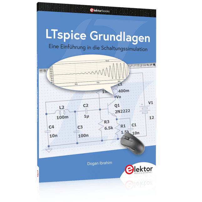
Elektor Publishing LTspice Grundlagen
Eine Einführung in die Schaltungssimulation LTspice wurde von Mike Engelhardt entwickelt und gehört inzwischen zu Analog Devices. Es handelt sich dabei um ein Programm zur Schaltplanerstellung – einen leistungsstarken, schnellen und kostenlosen SPICE-Simulator sowie um ein Werkzeug zur Darstellung von Kurvenverläufen. Es bietet eine umfangreiche Bauteildatenbank, die weltweit durch SPICE-Modelle unterstützt wird. Mit LTspice kann man schnell und einfach Schaltpläne erstellen. Dank der leistungsfähigen grafischen Ausgabefunktionen lassen sich Spannungen und Ströme in einer Schaltung, die Leistungsaufnahme der Bauteile und viele weitere Parameter darstellen. Ziel dieses Buches ist es, den Entwurf und die Simulation elektronischer Schaltungen mit LTspice zu vermitteln. Es behandelt unter anderem folgende Themen: DC und AC-Schaltungen Kleinsignal- und Z-Dioden Transistorschaltungen inkl. Oszillatoren Tryristor-, Diac- und Triacschaltungen Operationsverstärkerschaltungen inkl. Oszillatoren Der 555 Timer-IC Filter Spannungsregler Optokoppler Erstellung von Spannungskurven Simulation von Logikschaltungen mit der 74HC-Familie SPICE-Modellierung LTspice ist ein äußerst vielseitiges Werkzeug zur Simulation elektronischer Schaltungen mit zahlreichen Funktionen und Anwendungsmöglichkeiten. Eine vollständige Behandlung aller Details würde jedoch den Rahmen dieses Buches sprengen. Daher konzentriert sich das Buch auf die gängigsten Themen wie DC- und AC-Analyse, Parametersweep, Übertragungsfunktionen, Oszillatoren, Diagramme und weitere grundlegende Anwendungen. Obwohl es sich um eine Einführung handelt, deckt dieses Buch dennoch die meisten Interessensgebiete all jener ab, die sich mit der Simulation elektronischer Schaltungen beschäftigen.
€ 39,80
Bestpreis
-

€ 32,95
Mitglieder: € 29,66
-

Elecrow Elecrow AI Starter Kit für Jetson Orin Nano
All-in-One-Plattform für KI-Lernen und -Entwicklung im Bereich Edge Intelligence Dieses auf dem NVIDIA Jetson Orin Nano basierende KI-Starter-Kit ist eine vielseitige Plattform für Lernen, Entwicklung und praktische Experimente im Bereich Edge AI. Das für den Einsatz mit dem NVIDIA Jetson Orin Nano konzipierte Kit kombiniert ein 11,6-Zoll-IPS-Display, eine schwenk- und neigbare 8-Megapixel-Kamera sowie ein KI-gestütztes Sprachinteraktionssystem. Es umfasst 30 Funktionsmodule und 38 sorgfältig ausgearbeitete Python-Kurse, die vom Anfänger- bis zum Fortgeschrittenenniveau reichen. Die Kursinhalte decken Python-Grundlagen, Sensortechnologie, KI-basierte Bildverarbeitung (AI Vision) und Objekterkennung ab. Dank praktischer Schritt-für-Schritt-Übungen – von der grundlegenden Programmierung bis hin zu praxisnahen Computer-Vision-Anwendungen – bietet dieses Kit eine ideale Plattform für Schüler, Maker, Entwickler und alle, die sich mit künstlicher Intelligenz und Edge Computing beschäftigen möchten. Hinweis: Der NVIDIA Jetson Orin Nano ist nicht im Lieferumfang enthalten. Features Entwickelt für den NVIDIA Jetson Orin Nano KI-Sprachinteraktionsmodul 8-MP-Kamera mit Schwenk-Neige-Steuerung Unterstützt Objekt- und Gesichtserkennung (Tracking) Kein Löten oder aufwendige Verkabelung erforderlich Integriertes 11,6-Zoll-IPS-Display 30 Funktionsmodule 38 Schritt-für-Schritt-Python-Lektionen Erweiterungsschnittstellen für I²C, UART und GPIO Tragetasche im Lieferumfang enthalten Technische Daten Hauptprozessor Jetson Orin Nano Anzahl der Sensoren 30 Design des Sensor-Boards Integriertes Sensor-Board; kein Löten oder aufwendige Verkabelung erforderlich Bildschirm 11,6-Zoll-IPS-Bildschirm Bildschirmauflösung 1366 x 768 Kamera IMX219 8 MP Erweiterungsschnittstellen 2x I²C, 1x UART, 1x IO D13, 1x IO D12 Programmierumgebung Python-basiert Anzahl der Tutorials 38 kreative Tutorials Zielgruppe Schüler, Lehrkräfte, Hardware-Enthusiasten Anwendungsszenarien Ideal zum Erlernen der KI-Programmierung und der Grundlagen des Jetson Orin Nano Abmessungen 300 x 200 x 100 mm Modulliste Modul Anzahl Temperatur- und Feuchtigkeitssensor 1 Stk. Taster 4 Stk. Ultraschall-Abstandssensor 1 Stk. Lichtsensor 1 Stk. Linear-Potentiometer 1 Stk. Summer 1 Stk. LCD 1 Stk. Infrarot-Fernbedienung 1 Stk. Relais 1 Stk. NFC 1 Stk. PIR-Bewegungssensor 1 Stk. Joystick 1 Stk. 4-stelliges Display 1 Stk. LED 1 Stk. Mikrofon 1 Stk. Lautsprecher 1 Paar Vibrationsmotor 1 Stk. Berührungssensor 1 Stk. 8x8-RGB-Matrix 1 Stk. Luftdrucksensor 1 Stk. Neigungsschalter 1 Stk. Schrittmotor 1 Stk. Beschleunigungs- und Gyroskopsensor 1 Stk. Gassensor (MQ2) 1 Stk. Hall-Sensor 1 Stk. Drehgeber (Rotary Encoder) 1 Stk. Gabellichtschranke 1 Stk. NTC 1 Stk. Servo 2 Stk. Monokulare Kamera 1 Stk. Lieferumfang 1x Elecrow AI Starter Kit für Jetson Orin Nano 1x IR-Fernbedienung 1x NFC-Karte 1x 128 GB SD-Karte 1x 40-Pin-GPIO-Kabel 2x 22-Pin-FPC-Kabel 2x 24-Pin-FPC-Kabel 1x Jetson-DP- und USB-Adapterplatine Nicht enthalten NVIDIA Jetson Orin Nano Downloads Manual Wiki OpenClaw Install and Config Guide
€ 249,00
Mitglieder: € 224,10
-

Elektor Publishing Arduino for STM32
Learning Embedded Systems with STM32 Nucleo Boards Embedded programming has become more accessible than ever before. Development boards are inexpensive, software tools are easy to install, and the Arduino IDE provides a familiar environment for creating embedded applications. Combined with the STM32 Nucleo family of development boards, it offers an excellent platform for learning how modern microcontrollers interact with the physical world. This book introduces embedded programming using the Arduino environment on STM32 Nucleo boards. You will learn how a microcontroller continuously reads inputs, processes information, and controls outputs in a predictable real-time loop. Through practical examples, you will discover how to control LEDs, read switches and sensors, generate PWM signals, drive motors, and exchange data with other devices, all while becoming familiar with the capabilities of STM32 microcontrollers. Although the STM32 family includes devices with different performance levels, memory sizes, and peripheral sets, they all share the same architectural concepts. Digital and analog I/O, timers, interrupts, PWM, communication interfaces, and low-power operation are fundamental features found throughout the STM32 ecosystem. Understanding these building blocks will enable you to work confidently with a wide range of STM32 devices, from entry-level microcontrollers to more advanced applications. By focusing on practical programming techniques rather than hardware complexity, this book develops skills that remain useful well beyond the examples presented. Whether you are taking your first steps in embedded systems or expanding your experience with STM32 microcontrollers, you will gain a solid understanding of both the Arduino development environment and the principles that underpin embedded software design.
€ 27,95
Mitglieder: € 25,16


