
Suchergebnisse für "avr OR software OR defined OR radio OR 100182 OR 72"
-

Elektor Digital Elektor March/April 2023 (PDF)
Elektor GREEN and GOLD members can download their digital edition here. Not a member yet? Click here. Cloc 2.0The Alarm Clock You've Always Wanted RP2040 PIO in PracticeExperiments Using the RP2040’s Programmable I/O Poor Man's ChipTweakerWe Have (Low-Budget) Ways of Making You Talk USB True Random Number GeneratorTwo PICs for the Price of One AVR Pimp My MicSelf-Designed Level Booster FFT with a MaixduinoFrequency spectrum display From Life’s ExperienceDesign Logic (or Non-Logic) UCN5804 Stepper Motor DriverPeculiar Parts, the Series Circuit Simulation With Micro-CapFirst Steps in a Complicated World PAUL Award 2022Young Technical Talents and Their Creative Solutions My First Software-Defined RadioBuilt in Less Than 15 Minutes Microcontroller Documentation Explained (Part 1)Datasheet structure What’s Next for AI and Embedded Systems?Tools, Platforms, and Writer Replacements Digitizing Vertical Farming Infographics: Embedded and AI Today and Tomorrow An Introduction to TinyML JetCarrier96A Versatile NVIDIA Jetson Development System Case Study: Taking EV Charging Global with a Universal RFID Solution High-Performance in Every ClassComputer-on-Module Standards Starting Out in ElectronicsLet’s Get Active! I²C Communication Using Node.js and a Raspberry PiSee Your Sensor Data in a Browser Video Output with Microcontrollers (2)VGA and DVI Output The Metronom Real-Time Operating SystemAn RTOS for AVR Processors DVI on the RP2040An Interview with Luke Wren, Chip Developer at Raspberry Pi Display HAT MiniShow the Weather Forecast on Raspberry Pi! WEEF 2022 Awards: Celebrate the Good Hexadoku
€ 7,50
-

Rigol Rigol RSA3015E-TG Echtzeit-Spektrum-Analyzer (9 kHz – 1,5 GHz)
Highlights Frequenz: 1,5 GHz DANL: -161 dBm Phasenrauschen: -102 dBc/Hz RBW: 1Hz Technische Daten Ultra Real-Technologie Frequenz: bis zu 1,5 GHz Angezeigter durchschnittlicher Geräuschpegel (DANL): <-161 dBm (typisch) Phasenrauschen: <-102 dBc/Hz (typisch) Pegelmessunsicherheit: <1,0 dB 1,5-GHz-Tracking-Generator Mindest. RBW 1Hz Bis zu 10 MHz Echtzeit-Analysebandbreite Mehrere Messmodi Verschiedene erweiterte Messfunktionen EMI-Messanwendung (Option) Mehrere Triggermodi und Triggermasken Dichte, Spektrogramm und andere Anzeigemodi PC-Softwareoptionen 10,1'' kapazitiver Multi-Touchscreen; Unterstützung von Touch-Gesten USB, LAN, HDMI und andere Kommunikations- und Anzeigeschnittstellen Lieferumfang 1x Rigol RSA3015E-TG Spektrum-Analyzer 1x Netzkabel 1x USB-Kabel
€ 2.176,79
Bestpreis
-

Elektor Digital Funkempfänger-Kompendium (PDF)
Wollten Sie schon immer wissen, wie sich die klassische Funkempfängertechnik fortentwickelt hat? Wie funktionieren professionelle Funkempfänger heute und was können sie leisten? Wie ist es der modernen Funküberwachung und den Nachrichtendiensten möglich, gleich ganze Frequenzbänder in kürzester Zeit auszuforschen? Welche Empfangssysteme und Techniken stehen heute zur Verfügung? Möchten Sie auch ausgefallene Anwendungen von Empfängern kennenlernen und wissen, wie ein Software Defined Radio (Digitalempfänger) nun wirklich funktioniert und was der letzte Stand der entsprechenden Technik kann? Wodurch unterscheiden sich Kreuzmodulation und Intermodulation und worauf ist bei der messtechnischen Bestimmung und Datenblattvergleichen unbedingt zu achten? Warum folgen Intermodulationsprodukte nicht immer den Darstellungen von Lehrbüchern? Welche Artefakte zeigen digital nachgebildete Signalverarbeitungsketten abweichend von analogen Schaltungsstufen? Welche Auswirkungen haben derartige Kenngrößen tatsächlich auf die Empfangspraxis und warum kommt es nicht nur auf den IP3 an? Wie hängt beispielsweise die Grenzempfindlichkeit mit der Empfangsbandbreite zusammen? Was unterscheidet einen Signal/Rauschabstand nach der Beurteilung durch SINAD und (S+N)/N? Wie ist ein Empfangssystem zur Aufnahme kleinster Signalpegel zu optimieren? Fragen über Fragen – im vorliegenden Buch findet man die Antworten! Ausführlich und mit Details. Mit vielen speziell dafür erdachten Zeichnungen zur visuellen Erläuterung der Zusammenhänge. Mit durchgerechneten Fallbeispielen und dem stetigen Bezug zur Empfangspraxis. Großer Wert wurde den Darstellungen auf einheitliche Betrachtungsweise und durchgehende Systematik gelegt. Das erhöht die Übersichtlichkeit und erleichtert den Vergleich einzelner Vorgänge, Konzepte und Anlagen. Um den tatsächlichen Stand der Technik gut zu erfassen, wurden dutzende Patentschriften recherchiert und die Industrie mit eingebunden. Durch das sorgfältig aufbereitete Stichwortverzeichnis mit über 1200 Einträgen lassen sich die entsprechenden Stellen mit den Erklärungen rasch und punktgenau auffinden. Auch über die Thematik von Funkempfängern hinaus wird beim Studium der Lektüre vieles klar! Denn auch Messgeräte der Hochfrequenztechnik funktionieren vielmals nach ähnlichen Prinzipien. Wer den Inhalt durcharbeitet, kann wichtige Eigenschaften verstehen, beispielsweise von Spektrumanalysatoren und bei der Arbeit damit professionell vorgehen. Diese überarbeitete und erweiterte Neuauflage bringt erstmals sämtliche Bilder durchgehend in Vollfarbdruck, vertieft spezielle Themenschwerpunkte und bietet zusätzliche Fach- und Detailinformationen hinsichtlich den Realisierungsbeispielen gegenwärtiger Funkempfänger wie ferner durch das ergänzende Erörtern von jüngst verwendeten Messverfahren. Mit dem Erarbeiten und der Einbindung eines besonders umfangreichen, auf die Belange der heutigen Empfängertechnik zugeschnittenen Fach- und Übersetzungsglossars liegt zur Deutung entsprechender Fachbegriffe nunmehr eine Referenz vor.
€ 44,80
Mitglieder: € 40,32
-

OWON OWON ADS924A 4-Kanal Oszilloskop (250 MHz)
Die OWON ADS900A-Serie ist ein kompaktes 12-Bit-Digitaloszilloskop mit bis zu 2 GSa/s, 100 MPTS Speicher und 125/250 MHz Bandbreite. Mit seinem 7"-Multitouch-Display, FFT, Protokolldekodierung und integriertem Logikanalysator ermöglicht es eine präzise Signalanalyse für Labor-, Werkstatt- und Feldanwendungen. Technische Daten ADS914A ADS924A Bandwidth (-3 dB) 125 MHz 250 MHz Channels 4 Max. sample rate 2 GSa/s (single-channel) 1 GSa/s (dual-channel) 500 MSa/s (full-channel) DC Gain Accuracy 3% (≤1 mV) 2% (≥2 mV) Max memory depth 100M Vertical resolution 12 bits Relay time accuracy ±25 ppm (typical) Input Impedance 1 MΩ±2%, parallel with20 pF±5 pF Probe Attenuation Coefficient 1.00μX-1M.00X,step by 1-2-5, support custom Trigger type Edge, Video, Pulse, Slope, Runt, Windows, Timeout, Nth, Logic, RS232/UART, I²C, SPI CAN, LIN Bus decoding RS232/UART, I²C, SPI, CAN, LIN Auto measurement Period, Frequency, +Width, -Width, Rise Time, Fall Time, Scr Duty, +Duty,-Duty, Vavg, Vpp, VRMS, Overshoot, Vmax, Vmin, Vtop, CycRms, Vbase, Vamp, Preshoot, Std Dev, +Pulse Cnt, -Pulse Cnt, Rise Cnt, Fall Cnt, Area, Cyc Area, Delay(A↑-B↑), Delay(A↑-B↓), Delay(A↓-B↑), Delay(A↓-B↓), Phase(A↑-B↑) Phase(A↑-B↓), Phase(A↓-B↑), Phase(A↓-B↓), FRR(A↑-B↑), FRF(A↑-B↓) FFR(A↓-B↑), FFF(A↓-B↓), LRR(A↑-B↑), LRF(A↑-B↓), LFR(A↓-B↑), LFF(A↓-B↓) Waveform Math +, -, *, /, &&, ||, ^, !, Intg, Diff, Sqrt, Function operation (Lg / Ln / Exp / Abs / Sine / Cosine / Tan), FFT, FFT rms, User Defined, digital filter (low pass, high pass, band pass, band reject) Frequency counter 6-digit frequency counter Maximum frequency: maximum analog bandwidth of oscilloscope Voltmeter Support DC, AC+DCrms, ACrms, Resolution: 4 digits (ACV/DCV) Logical Analyzer Specifications Number of channels 16 input channels (D0-D15) (D0 to D7, D8 to D15) Max. input voltage ±40V peak CAT I, transient overvoltage 800Vpk Input Impedance 100kΩ, 8 pF Vertical resolution 1 bit Other Communication Interface HDMI, USB device, USB Host, Trig Out (P/F), LAN Display 7 inch (1024x600), capacitive multi-touch screen Power supply interface USB-C Dimensions 260 x 160 x 78 mm Weight 1.5 kg Lieferumfang 1x OWON ADS924A Oszilloskop 1x Netzteil 1x Netzkabel 1x USB-Kabel 1x Sonde 1x Quick Guide Downloads Manual Quick Guide PC Software
€ 677,11
-

Elektor Digital Mastering Microcontrollers Helped by Arduino (3rd Edition) | E-book
Third, extended and revised edition with AVR Playground and Elektor Uno R4 Arduino boards have become hugely successful. They are simple to use and inexpensive. This book will not only familiarize you with the world of Arduino but it will also teach you how to program microcontrollers in general. In this book theory is put into practice on an Arduino board using the Arduino programming environment. Some hardware is developed too: a multi-purpose shield to build some of the experiments from the first 10 chapters on; the AVR Playground, a real Arduino-based microcontroller development board for comfortable application development, and the Elektor Uno R4, an Arduino Uno R3 on steroids. The author, an Elektor Expert, provides the reader with the basic theoretical knowledge necessary to program any microcontroller: inputs and outputs (analog and digital), interrupts, communication busses (RS-232, SPI, I²C, 1-wire, SMBus, etc.), timers, and much more. The programs and sketches presented in the book show how to use various common electronic components: matrix keyboards, displays (LED, alphanumeric and graphic color LCD), motors, sensors (temperature, pressure, humidity, sound, light, and infrared), rotary encoders, piezo buzzers, pushbuttons, relays, etc. This book will be your first book about microcontrollers with a happy ending! This book is for you if you are a beginner in microcontrollers, an Arduino user (hobbyist, tinkerer, artist, etc.) wishing to deepen your knowledge,an Electronics Graduate under Undergraduate student or a teacher looking for ideas. Thanks to Arduino the implementation of the presented concepts is simple and fun. Some of the proposed projects are very original: Money Game Misophone (a musical fork) Car GPS Scrambler Weather Station DCF77 Decoder Illegal Time Transmitter Infrared Remote Manipulator Annoying Sound Generator Italian Horn Alarm Overheating Detector PID Controller Data Logger SVG File Oscilloscope 6-Channel Voltmeter All projects and code examples in this book have been tried and tested on an Arduino Uno board. They should also work with the Arduino Mega and every other compatible board that exposes the Arduino shield extension connectors. Please note For this book, the author has designed a versatile printed circuit board that can be stacked on an Arduino board. The assembly can be used not only to try out many of the projects presented in this book but also allows for new exercises that in turn provide the opportunity to discover new techniques. Also available is a kit of parts including the PCB and all components. With this kit you can build most of the circuits described in the book and more. Datasheets Active Components Used (.PDF file): ATmega328 (Arduino Uno) ATmega2560 (Arduino Mega 2560) BC547 (bipolar transistor, chapters 7, 8, 9) BD139 (bipolar power transistor, chapter 10) BS170 (N-MOS transistor, chapter 8) DCF77 (receiver module, chapter 9) DS18B20 (temperature sensor, chapter 10) DS18S20 (temperature sensor, chapter 10) HP03S (pressure sensor, chapter 8) IRF630 (N-MOS power transistor, chapter 7) IRF9630 (P-MOS power transistor, chapter 7) LMC6464 (quad op-amp, chapter 7) MLX90614 (infrared sensor, chapter 10) SHT11 (humidity sensor, chapter 8) TS922 (dual op-amp, chapter 9) TSOP34836 (infrared receiver, chapter 9) TSOP1736 (infrared receiver, chapter 9) MPX4115 (analogue pressure sensor, chapter 11) MCCOG21605B6W-SPTLYI (I²C LCD, chapter 12) SST25VF016B (SPI EEPROM, chapter 13) About the author Clemens Valens, born in the Netherlands, lives in France since 1997. Manager at Elektor Labs and Webmaster of ElektorLabs, in love with electronics, he develops microcontroller systems for fun, and sometimes for his employer too. Polyglot—he is fluent in C, C++, PASCAL, BASIC and several assembler dialects—Clemens spends most of his time on his computer while his wife, their two children and two cats try to attract his attention (only the cats succeed). Visit the author’s website: www.polyvalens.com.Authentic testimony of Hervé M., one of the first readers of the book:'I almost cried with joy when this book made me understand things in only three sentences that seemed previously completely impenetrable.'
€ 34,95
Mitglieder: € 31,46
-

OWON OWON XDG2035 2-Kanal Funktionsgenerator (35 Mhz)
Der 2-Kanal OWON XDG2035 ist ein Funktions-/Wellenformgenerator, der Signale mit einer maximalen Frequenz von 35 MHz erzeugen kann. Der Generator hat eine Auflösung von 1 µHz und eine Abtastrate von 500 MSa/s.Der OWON XDG2035 ist in der Lage, 6 Standardwellenformen und 150 Arbiträrwellenformen zu erzeugen. Mit der mitgelieferten Software können Sie erweiterte Funktionen bis zu 10 Millionen Punkte schreiben. Wellenformen können mit einem PC über USB oder LAN im internen Speicher des Funktionsgenerators gespeichert werden.Der OWON XDG2035 unterstützt auch SCPI-Befehle und LabView. Der Funktionsgenerator verfügt über einen integrierten hochwertigen Frequenzzähler, der von 100 bis 200 MHz arbeiten kann.FeaturesMax. 35 MHz Frequenzausgang500 MSa/s Abtastrate, vertikale Auflösung 1 μHz14 Bit vertikale Auflösung, 10 Marb WellenformlängeUmfassende Wellenformausgabe: 6 Grundwellenformen und 150 integrierte ArbiträrwellenformenUmfassende Modulationsfunktionen: AM, FM, PM, FSK, 3FSK, 4FSK, PSK, OSK, ASK, BPSK, PWM, Sweep und BurstHochpräziser Frequenzzähler integriert, unterstützter Bereich 100-200 MHzSCPI und LabVIEW werden unterstützt7 Zoll Multi-Touch-Bildschirm (800 x 480 Pixel)Technische DatenKanäle2Frequenzausgang35 MHzAbtastrate500 MSa/sVertikale Auflösung14 bitsWellenform Standard WaveformSine, square, pulse, ramp, noise, and harmonicArbitrary WaveformExponential rise, exponential fall, sin(x)/x, step wave, and others, total 150 built-in waveforms, and user-defined arbitrary waveformFrequenz (Auflösung 1 μHz) Sine1 μHz-100 MHzSquare1 μHz ~ 30 MHzPulse1 μHz ~ 25 MHzRamp1 μHz ~ 3 MHzNoise (-3 dB, typical)100 MHzArbitrary Waveform1 μHz ~ 15 MHzHarmonic1 μHz ~ 50 MHzAccuracy±2ppm, 25°C ±5°CWaveform Length2 points - 10M pointsAmplitude Into 50Ω load1mVpp ~ 10Vpp (≤25 MHz); 1mVpp ~ 5Vpp (≤60 MHz); 1mVpp ~ 2.5Vpp (≤100 MHz)Modulation TypeAM, DSB-AM, FM, PM, ASK, FSK, PSK, BPSK, QPSK, 3FSK, 4FSK, OSK, PWM, SUMFrequenzzähler FunctionFrequency, period, +width, -width, +duty, and -dutyFrequency Range100 ~ 200 MHzFrequency Resolution7 digitsInput/Output Input modefrequency counter, external modulation input, external trigger input, internal clock output, external reference clock input/outputCommunication InterfaceUSB Host, USB Device, LAN, RS232 (optional)Mechanische Spezifikationen Abmessungen340 x 177 x 90 mmGewicht2,3 kgLieferumfang1x OWON XDG20351x Netzkabel1x CD-ROM1x Kurzanleitung1x USB-Kabel1x BNC-BNC-KabelDownloadsQuick Guide
€ 333,40
-

OWON OWON ADS914A 4-Kanal Oszilloskop (125 MHz)
Die OWON ADS900A-Serie ist ein kompaktes 12-Bit-Digitaloszilloskop mit bis zu 2 GSa/s, 100 MPTS Speicher und 125/250 MHz Bandbreite. Mit seinem 7"-Multitouch-Display, FFT, Protokolldekodierung und integriertem Logikanalysator ermöglicht es eine präzise Signalanalyse für Labor-, Werkstatt- und Feldanwendungen. Technische Daten ADS914A ADS924A Bandwidth (-3 dB) 125 MHz 250 MHz Channels 4 Max. sample rate 2 GSa/s (single-channel) 1 GSa/s (dual-channel) 500 MSa/s (full-channel) DC Gain Accuracy 3% (≤1 mV) 2% (≥2 mV) Max memory depth 100M Vertical resolution 12 bits Relay time accuracy ±25 ppm (typical) Input Impedance 1 MΩ±2%, parallel with20 pF±5 pF Probe Attenuation Coefficient 1.00μX-1M.00X,step by 1-2-5, support custom Trigger type Edge, Video, Pulse, Slope, Runt, Windows, Timeout, Nth, Logic, RS232/UART, I²C, SPI CAN, LIN Bus decoding RS232/UART, I²C, SPI, CAN, LIN Auto measurement Period, Frequency, +Width, -Width, Rise Time, Fall Time, Scr Duty, +Duty,-Duty, Vavg, Vpp, VRMS, Overshoot, Vmax, Vmin, Vtop, CycRms, Vbase, Vamp, Preshoot, Std Dev, +Pulse Cnt, -Pulse Cnt, Rise Cnt, Fall Cnt, Area, Cyc Area, Delay(A↑-B↑), Delay(A↑-B↓), Delay(A↓-B↑), Delay(A↓-B↓), Phase(A↑-B↑) Phase(A↑-B↓), Phase(A↓-B↑), Phase(A↓-B↓), FRR(A↑-B↑), FRF(A↑-B↓) FFR(A↓-B↑), FFF(A↓-B↓), LRR(A↑-B↑), LRF(A↑-B↓), LFR(A↓-B↑), LFF(A↓-B↓) Waveform Math +, -, *, /, &&, ||, ^, !, Intg, Diff, Sqrt, Function operation (Lg / Ln / Exp / Abs / Sine / Cosine / Tan), FFT, FFT rms, User Defined, digital filter (low pass, high pass, band pass, band reject) Frequency counter 6-digit frequency counter Maximum frequency: maximum analog bandwidth of oscilloscope Voltmeter Support DC, AC+DCrms, ACrms, Resolution: 4 digits (ACV/DCV) Logical Analyzer Specifications Number of channels 16 input channels (D0-D15) (D0 to D7, D8 to D15) Max. input voltage ±40V peak CAT I, transient overvoltage 800Vpk Input Impedance 100kΩ, 8 pF Vertical resolution 1 bit Other Communication Interface HDMI, USB device, USB Host, Trig Out (P/F), LAN Display 7 inch (1024x600), capacitive multi-touch screen Power supply interface USB-C Dimensions 260 x 160 x 78 mm Weight 1.5 kg Lieferumfang 1x OWON ADS914A Oszilloskop 1x Netzteil 1x Netzkabel 1x USB-Kabel 1x Sonde 1x Quick Guide Downloads Manual Quick Guide PC Software
€ 570,01
-
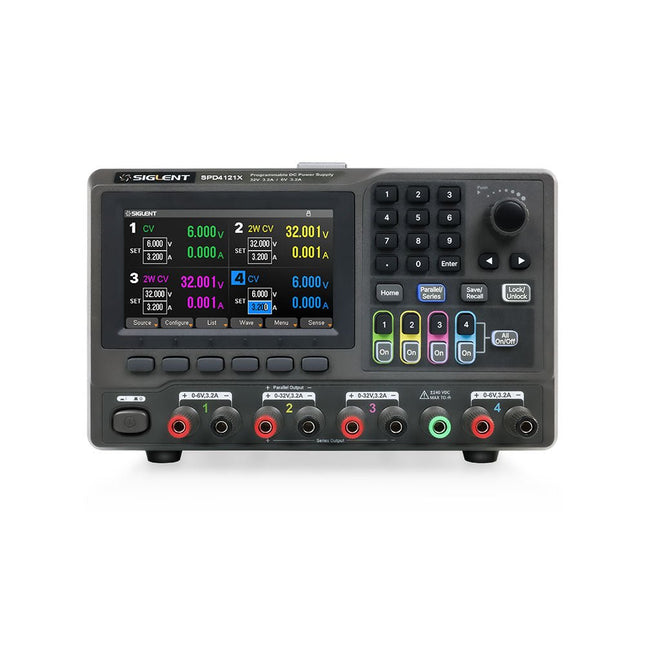
Siglent Siglent SPD4121X 4-Kanal Netzteil (285 W)
The Siglent SPD4121X is a 4-channel DC Linear Programmable Power Supply equipped with a 4.3-inch TFT-LCD display, friendly human-machine interface, and excellent performance indicators. Real-time waveform display provides engineers with an informative user interface. SPD4121X offers a total output power of 285 W with a resolution of 1 mV/1 mA. The maximum voltage and current for each channel are as follows: CH1: 15 V/1.5 A CH2: 12 V/10 A CH3: 12 V/10 A CH4: 15 V/1.5 A Features Rated output power: 285 W Rated voltage: 32 V, 12 V, 30 V Up to four high-precision power supplies with independent controllable outputs, supporting CH2 and CH3 series and parallel connections Clear graphical interface with waveform and timer display modes 5-digit voltage and current display with minimum resolution of 1 mV, 1 mA Fast output response time: <50us The high current channel support remote voltage compensation sense function. The maximum compensation voltage is 0.6 V Overvoltage protection and overcurrent protection or safe and accurate operation Equipped with a 4.3-inch TFT-LCD display (480 x 272 resolution) USB and LAN standard communication USB-GPIB module is optional Excellent channel density with up to 4 channels in a 3U half rack package Internal data storage for setups and parameters Embedded Web Server with instrument communication that doesn’t require software installation Fully SCPI programming command set support as well as a LabView driver for remote control and system automation Technische Daten SPD4323X SPD4121X SPD4306X Channel Output CH1: Voltage 0 to 6 V Current 0 to 3.2 ACH2: Voltage 0 to 32 V Current 0 to 3.2 ACH3: Voltage 0 to 32 V Current 0 to 3.2 ACH4: Voltage 0 to 6 V Current 0 to 3.2 A CH1: Voltage 0 to 15 V Current 0 to 1.5 ACH2: Voltage 0 to 12 V Current 0 to 10 ACH3: Voltage 0 to 12 V Current 0 to 10 ACH4: Voltage 0 to 15 V Current 0 to 1.5 A CH1: Voltage 0 to 15 V Current 0 to 1.5 ACH2: Voltage 0 to 30 V Current 0 to 6 ACH3: Voltage 0 to 30 V Current 0 to 6 ACH4: Voltage 0 to 15 V Current 0 to 1 A Resolution 1 mV, 1 mA 1 mV, 1 mA 1 mV, 1 mA Setting Accuracy Voltage: ±(0.03% of reading+10) mV, Current: ±(0.3% of reading+10) mA Voltage: ±(0.03% of reading+10) mV, Current: ±(0.3% of reading+10) mA Voltage: ±(0.03% of reading+10) mV, Current: ±(0.3% of reading+10) mA Readback Accuracy Voltage: ±(0.03% of reading+10) mV, Current: ±(0.3% of reading+10) mA Voltage: ±(0.03% of reading+10) mV, Current: ±(0.3% of reading+10) mA Voltage: ±(0.03% of reading+10) mV, Current: ±(0.3% of reading+10) mA Display 4.3" TFT-LCD 5-digit voltage and current display 4.3" TFT-LCD 5-digit voltage and current display 4.3" TFT-LCD 5-digit voltage and current display Output power 240 W 285 W 400 W Lieferumfang 1x Siglent SPD4121X Power Supply 1x Power cord (EU) 1x Output test cord (3 A) 1x USB cable 1x Quick start guide Downloads Datasheet Manual Quick start
€ 871,20
Bestpreis
-

FNIRSI FNIRSI SG-003A Signalgenerator
Der FNIRSI SG-003A ist ein kleiner, hochpräziser Signalgenerator mit einem 2,4' TFT-Farbdisplay mit einem Frequenzbereich von bis zu 10 kHz und einem aktiven und passiven Stromausgang von 24 mA. Die maximale Ausgangsspannung beträgt 24 V. Die eingebaute 3000-mAh-Lithiumbatterie hat eine Laufzeit von 10 Stunden. FNIRSI SG-003A wird hauptsächlich für die Fehlersuche in industriellen SPS, Prozessinstrumenten, elektrischen Ventilen usw. verwendet. Features Genauigkeit (Spannung/Strom) 0,1% ±0,005 Auflösung (aktuell) 0,01 mA Frequenz 0-10 kHz Auflösung 5 Ziffern Ausgangsleistung 24 V Display 2,4" TFT-LCD (320 x 240) Abmessungen 92 x 72 x 30 mm Gewicht 165 g Technische Daten Signal Bereich Genauigkeit Auflösung Maximale Belastung Externe Stromversorgung Aktiver Stromausgang 0~24 mA ±(0,1% + 0,005) 0,01 mA 750 Ω Passiver Stromausgang (XMT) 0~24 mA ±(0,1% + 0,005) 0,01 mA 0~30 V Spannungsausgang 0~24 V ±(0,1% + 0,005) 0,01 V 24-V-Schleife 0~24 mA ±(0,1% + 0,005) 0,01 mA Frequenzausgang 0~9999 Hz ±2% 5 Ziffern Stromeingang 0~24 mA ±(0,1% + 0,005) 0,01 mA Spannungseingang 0~30 V ±(0,1% + 0,005) 0,01 V Lieferumfang 1x FNIRSI SG-003A Signalgenerator 4x Testclips 1x USB-Ladegerät 1x USB-C Kabel 1x Manual Downloads Manual Firmware V4.3
€ 68,79
-
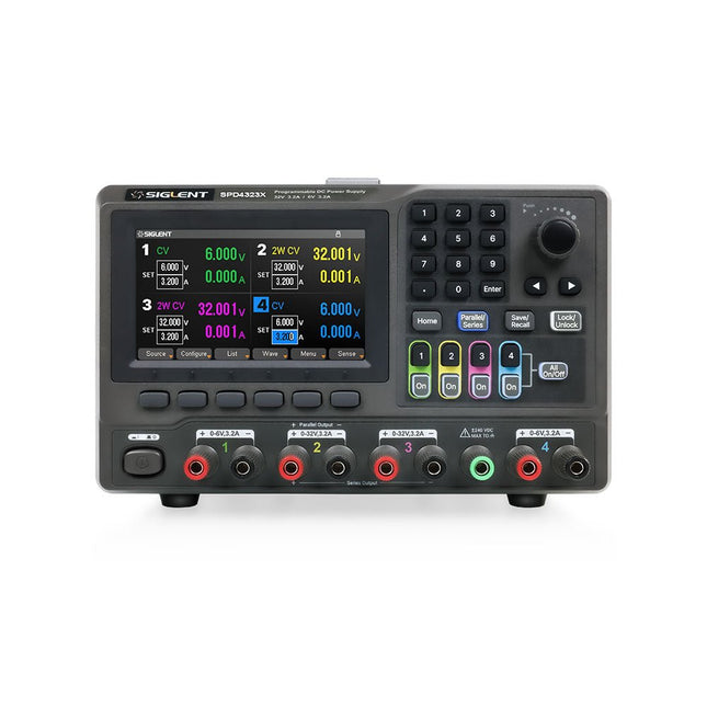
Siglent Siglent SPD4323X 4-Kanal Netzteil (240 W)
The Siglent SPD4323X is a 4-channel DC Linear Programmable Power Supply equipped with a 4.3-inch TFT-LCD display, friendly human-machine interface, and excellent performance indicators. Real-time waveform display provides engineers with an informative user interface. SPD4323X offers a total output power of 240 W with a resolution of 1 mV/1 mA. The maximum voltage and current for each channel are as follows: CH1: 6 V/3.2 A CH2: 32 V/3.2 A CH3: 32 V/3.2 A CH4: 6 V/3.2 A Features Rated output power: 240 W Rated voltage: 32 V, 12 V, 30 V Up to four high-precision power supplies with independent controllable outputs, supporting CH2 and CH3 series and parallel connections Clear graphical interface with waveform and timer display modes 5-digit voltage and current display with minimum resolution of 1 mV, 1 mA Fast output response time: <50us The high current channel support remote voltage compensation sense function. The maximum compensation voltage is 0.6 V Overvoltage protection and overcurrent protection or safe and accurate operation Equipped with a 4.3-inch TFT-LCD display (480 x 272 resolution) USB and LAN standard communication USB-GPIB module is optional Excellent channel density with up to 4 channels in a 3U half rack package Internal data storage for setups and parameters Embedded Web Server with instrument communication that doesn’t require software installation Fully SCPI programming command set support as well as a LabView driver for remote control and system automation Technische Daten SPD4323X SPD4121X SPD4306X Channel Output CH1: Voltage 0 to 6 V Current 0 to 3.2 ACH2: Voltage 0 to 32 V Current 0 to 3.2 ACH3: Voltage 0 to 32 V Current 0 to 3.2 ACH4: Voltage 0 to 6 V Current 0 to 3.2 A CH1: Voltage 0 to 15 V Current 0 to 1.5 ACH2: Voltage 0 to 12 V Current 0 to 10 ACH3: Voltage 0 to 12 V Current 0 to 10 ACH4: Voltage 0 to 15 V Current 0 to 1.5 A CH1: Voltage 0 to 15 V Current 0 to 1.5 ACH2: Voltage 0 to 30 V Current 0 to 6 ACH3: Voltage 0 to 30 V Current 0 to 6 ACH4: Voltage 0 to 15 V Current 0 to 1 A Resolution 1 mV, 1 mA 1 mV, 1 mA 1 mV, 1 mA Setting Accuracy Voltage: ±(0.03% of reading+10) mV, Current: ±(0.3% of reading+10) mA Voltage: ±(0.03% of reading+10) mV, Current: ±(0.3% of reading+10) mA Voltage: ±(0.03% of reading+10) mV, Current: ±(0.3% of reading+10) mA Readback Accuracy Voltage: ±(0.03% of reading+10) mV, Current: ±(0.3% of reading+10) mA Voltage: ±(0.03% of reading+10) mV, Current: ±(0.3% of reading+10) mA Voltage: ±(0.03% of reading+10) mV, Current: ±(0.3% of reading+10) mA Display 4.3" TFT-LCD 5-digit voltage and current display 4.3" TFT-LCD 5-digit voltage and current display 4.3" TFT-LCD 5-digit voltage and current display Output power 240 W 285 W 400 W Lieferumfang 1x Siglent SPD4323X Power Supply 1x Power cord (EU) 1x Output test cord (3 A) 1x USB cable 1x Quick start guide Downloads Datasheet Manual Quick start
€ 762,30
Bestpreis
-

Siglent Siglent SPD4306X 4-Kanal Netzteil (400 W)
The Siglent SPD4306X is a 4-channel DC Linear Programmable Power Supply equipped with a 4.3-inch TFT-LCD display, friendly human-machine interface, and excellent performance indicators. Real-time waveform display provides engineers with an informative user interface. SPD4306X offers a total output power of 400 W with a resolution of 1 mV/1 mA. The maximum voltage and current for each channel are as follows: CH1: 15 V/1.5 A CH2: 30 V/6 A CH3: 30 V/6 A CH4: 15 V/1 A Features Rated output power: 400 W Rated voltage: 32 V, 12 V, 30 V Up to four high-precision power supplies with independent controllable outputs, supporting CH2 and CH3 series and parallel connections Clear graphical interface with waveform and timer display modes 5-digit voltage and current display with minimum resolution of 1 mV, 1 mA Fast output response time: <50us The high current channel support remote voltage compensation sense function. The maximum compensation voltage is 0.6 V Overvoltage protection and overcurrent protection or safe and accurate operation Equipped with a 4.3-inch TFT-LCD display (480 x 272 resolution) USB and LAN standard communication USB-GPIB module is optional Excellent channel density with up to 4 channels in a 3U half rack package Internal data storage for setups and parameters Embedded Web Server with instrument communication that doesn’t require software installation Fully SCPI programming command set support as well as a LabView driver for remote control and system automation Technische Daten SPD4323X SPD4121X SPD4306X Channel Output CH1: Voltage 0 to 6 V Current 0 to 3.2 ACH2: Voltage 0 to 32 V Current 0 to 3.2 ACH3: Voltage 0 to 32 V Current 0 to 3.2 ACH4: Voltage 0 to 6 V Current 0 to 3.2 A CH1: Voltage 0 to 15 V Current 0 to 1.5 ACH2: Voltage 0 to 12 V Current 0 to 10 ACH3: Voltage 0 to 12 V Current 0 to 10 ACH4: Voltage 0 to 15 V Current 0 to 1.5 A CH1: Voltage 0 to 15 V Current 0 to 1.5 ACH2: Voltage 0 to 30 V Current 0 to 6 ACH3: Voltage 0 to 30 V Current 0 to 6 ACH4: Voltage 0 to 15 V Current 0 to 1 A Resolution 1 mV, 1 mA 1 mV, 1 mA 1 mV, 1 mA Setting Accuracy Voltage: ±(0.03% of reading+10) mV, Current: ±(0.3% of reading+10) mA Voltage: ±(0.03% of reading+10) mV, Current: ±(0.3% of reading+10) mA Voltage: ±(0.03% of reading+10) mV, Current: ±(0.3% of reading+10) mA Readback Accuracy Voltage: ±(0.03% of reading+10) mV, Current: ±(0.3% of reading+10) mA Voltage: ±(0.03% of reading+10) mV, Current: ±(0.3% of reading+10) mA Voltage: ±(0.03% of reading+10) mV, Current: ±(0.3% of reading+10) mA Display 4.3" TFT-LCD 5-digit voltage and current display 4.3" TFT-LCD 5-digit voltage and current display 4.3" TFT-LCD 5-digit voltage and current display Output power 240 W 285 W 400 W Lieferumfang 1x Siglent SPD4306X Power Supply 1x Power cord (EU) 1x Output test cord (3 A) 1x USB cable 1x Quick start guide Downloads Datasheet Manual Quick start
€ 1.101,10
Bestpreis
-

FLUX FLUX Ador Laserschneider (20 W)
FLUX Ador ist der weltweit erste Farbdruck-Laserschneider. Angetrieben von drei hochwertigen, austauschbaren Modulen ermöglicht Ador Ihnen das Gravieren und Schneiden einer Vielzahl von Materialien und verleiht Ihren Projekten gleichzeitig einen Hauch von Farbe. Neue kreative Möglichkeiten mit Ador Egal, ob Sie Ausbilder, Kleinunternehmer, Bastler oder Designer sind, mit Ador können Sie die Grenzen der Anwendung selbst festlegen. Einfach zu bedienen Material platzieren und dann automatisch fokussieren Drag & Drop deines Designs Gravieren, schneiden oder drucken Projekt fertig! Großer Arbeitsbereich, große Ideen Ador bietet einen großen Arbeitsraum von 430 x 300 mm und einer Tiefe von 30 mm und erweitert so den Horizont Ihrer Kreativität. Technische Daten Abmessungen 637 x 488 x 226 mm Gewicht 19 kg Arbeitsbereich X&Y: 20 W Diodenlaser: 430 x 300 mm (X & Y variiert je nach Modul)Z: 30 mm (für alle Module) & 20 mm (mit Prisma) Kameravorschaubereich Gesamter Arbeitsbereich Spannung Wechselstrom 110–240 V Touchpanel Ja, 8 Zoll (diagonal) Kamera 8 MP I/O USB / WLAN Laserspezifikation W-Diodenlasermodul Laserbewegungsgeschwindigkeit 0~400 mm/s Laserschnittdicke Variiert je nach Material Softwaremodus Vektor/Grafik (monochrom, Graustufen) Betriebssystem Windows / macOS / Linux Softwaredateityp JPG / PNG / SVG / DXF Enthalten FLUX Ador 20 W Diodenlasermodul 6-facher Prismenlift Netzteil Netzkabel Hex-Schlüssel Entlüftungsschlauch Entlüftungsschlauch-Kanalklemme Teststück aus Holz Laserschneider-Schmiermittel Downloads Firmware
€ 1.935,00
Bestpreis


