
Suchergebnisse für "standard OR 32bit OR pic OR licence OR flowcode OR 7"
-

Elektor Digital Elektor March/April 2023 (PDF)
Elektor GREEN and GOLD members can download their digital edition here. Not a member yet? Click here. Cloc 2.0The Alarm Clock You've Always Wanted RP2040 PIO in PracticeExperiments Using the RP2040’s Programmable I/O Poor Man's ChipTweakerWe Have (Low-Budget) Ways of Making You Talk USB True Random Number GeneratorTwo PICs for the Price of One AVR Pimp My MicSelf-Designed Level Booster FFT with a MaixduinoFrequency spectrum display From Life’s ExperienceDesign Logic (or Non-Logic) UCN5804 Stepper Motor DriverPeculiar Parts, the Series Circuit Simulation With Micro-CapFirst Steps in a Complicated World PAUL Award 2022Young Technical Talents and Their Creative Solutions My First Software-Defined RadioBuilt in Less Than 15 Minutes Microcontroller Documentation Explained (Part 1)Datasheet structure What’s Next for AI and Embedded Systems?Tools, Platforms, and Writer Replacements Digitizing Vertical Farming Infographics: Embedded and AI Today and Tomorrow An Introduction to TinyML JetCarrier96A Versatile NVIDIA Jetson Development System Case Study: Taking EV Charging Global with a Universal RFID Solution High-Performance in Every ClassComputer-on-Module Standards Starting Out in ElectronicsLet’s Get Active! I²C Communication Using Node.js and a Raspberry PiSee Your Sensor Data in a Browser Video Output with Microcontrollers (2)VGA and DVI Output The Metronom Real-Time Operating SystemAn RTOS for AVR Processors DVI on the RP2040An Interview with Luke Wren, Chip Developer at Raspberry Pi Display HAT MiniShow the Weather Forecast on Raspberry Pi! WEEF 2022 Awards: Celebrate the Good Hexadoku
€ 7,50
-

Elektor Digital Mastering the Arduino Uno R4 (E-book)
Programming and Projects for the Minima and WiFi Based on the low-cost 8-bit ATmega328P processor, the Arduino Uno R3 board is likely to score as the most popular Arduino family member, and this workhorse has been with us for many years. Eleven years later, the long-overdue successor, the Arduino Uno R4, was released. It is built around a 48 MHz, 32-bit Arm Cortex-M4 microcontroller and provides significantly expanded SRAM and Flash memory. Additionally, a higher-precision ADC and a new DAC are added to the design. The Uno R4 board also supports the CAN Bus with an interface. Two versions of the board are available: Uno R4 Minima, and Uno R4 WiFi. This book is about using these new boards to develop many different and interesting projects with just a handful of parts and external modules. All projects described in the book have been fully tested on the Uno R4 Minima or the Uno R4 WiFi board, as appropriate. The project topics include the reading, control, and driving of many components and modules in the kit as well as on the relevant Uno R4 board, including LEDs 7-segment displays (using timer interrupts) LCDs Sensors RFID Reader 4x4 Keypad Real-time clock (RTC) Joystick 8×8 LED matrix Motors DAC (Digital-to-analog converter) LED matrix WiFi connectivity Serial UART CAN bus Infrared controller and receiver Simulators … all in creative and educational ways with the project operation and associated software explained in great detail.
€ 34,95
Mitglieder: € 31,46
-

Rigol Rigol DG2102 Funktions-/Arbiträrwellenformgenerator (100 MHz)
Highlights Ausgangsfrequenz (Sinus): 100 MHz Ausgangsfrequenz (Rechteck): 25 MHz Kanäle: 2 Länge der beliebigen Wellenform: 16 Mpts Features Einzigartige SiFi II-Technologie (Signal Fidelity II): Generierung beliebiger Wellenformen Punkt für Punkt; Wiederherstellung des Signals ohne Verzerrung; genaue und anpassbare Abtastrate; Jitter aller Ausgangswellenformen (einschließlich Sinus, Puls usw.) nur 200 ps 16 Mpts Speichertiefe pro Kanal für beliebige Wellenformen Standardmäßiger Dual-Channel mit gleicher Leistung, entspricht zwei unabhängigen Signalquellen Hohe Frequenzstabilität: ±1 ppm; geringes Phasenrauschen: -105 dBc/Hz Eingebauter Harmonischengenerator höherer Ordnung (maximal Harmonische 8. Ordnung) Eingebauter Frequenzzähler mit 7 Ziffern/s und 240 MHz Bandbreite und vollem Funktionsumfang Bis zu 160 integrierte beliebige Wellenformen, die die gängigen Signale in technischen Anwendungen, der medizinischen Elektronik, der Autoelektronik, der mathematischen Verarbeitung und vielen anderen Bereichen abdecken Abtastrate bis zu 250 MSa/s, vertikale Auflösung 16 Bit Funktion zum Bearbeiten beliebiger Wellenformsequenzen verfügbar; beliebige Wellenformen können auch über die PC-Software generiert werden Verschiedene analoge und digitale Modulationsfunktionen: AM, FM, PM, ASK, FSK, PSK und PWM. Standardmäßige Wellenform-Kombinationsfunktion, die die Ausgabe bestimmter Wellenformen in Kombination mit den Basiswellenformen ermöglicht Standardmäßige Kanalverfolgungsfunktion. Wenn aktiviert, werden alle Parameter beider Kanäle basierend auf den Benutzerkonfigurationen aktualisiert. Standardschnittstelle: USB Host&Device und LAN (LXI Core 2011 Device); USB-GPIB-Funktion wird unterstützt 4,3-Zoll-TFT Lieferumfang 1x Rigol DG2102 Funktions-/Arbiträrwellenformgenerator 1x Netzkabel 1x USB-Kabel
€ 1.087,79
Bestpreis
-
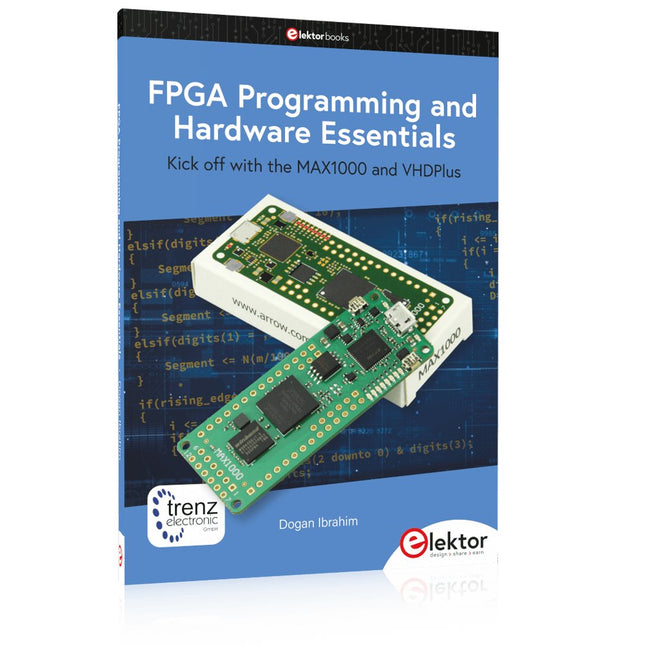
Elektor Publishing FPGA Programming and Hardware Essentials
Kick off with the MAX1000 and VHDPlus Ready to Master FPGA Programming? In this guide, we’re diving into the world of Field Programmable Gate Arrays (FPGAs) – a configurable integrated circuit that can be programmed after manufacturing. Imagine bringing your ideas to life, from simple projects to complete microcontroller systems! Meet the MAX1000: a compact and budget-friendly FPGA development board packed with features like memory, user LEDs, push-buttons, and flexible I/O ports. It’s the ideal starting point for anyone wanting to learn about FPGAs and Hardware Description Languages (HDLs). In this book, you’ll get hands-on with the VHDPlus programming language – a simpler version of VHDL. We’ll work on practical projects using the MAX1000, helping you gain the skills and confidence to unleash your creativity. Get ready for an exciting journey! You’ll explore a variety of projects that highlight the true power of FPGAs. Let’s turn your ideas into reality and embark on your FPGA adventure – your journey starts now! Exciting Projects You’ll Find in This Book Arduino-Driven BCD to 7-Segment Display Decoder Use an Arduino Uno R4 to supply BCD data to the decoder, counting from 0 to 9 with a one-second delay Multiplexed 4-Digit Event Counter Create an event counter that displays the total count on a 4-digit display, incrementing with each button press PWM Waveform with Fixed Duty Cycle Generate a PWM waveform at 1 kHz with a fixed duty cycle of 50% Ultrasonic Distance Measurement Measure distances using an ultrasonic sensor, displaying the results on a 4-digit 7-segment LED Electronic Lock Build a simple electronic lock using combinational logic gates with push buttons and an LED output Temperature Sensor Monitor ambient temperature with a TMP36 sensor and display the readings on a 7-segment LED Downloads Software
€ 39,95
Mitglieder: € 35,96
-
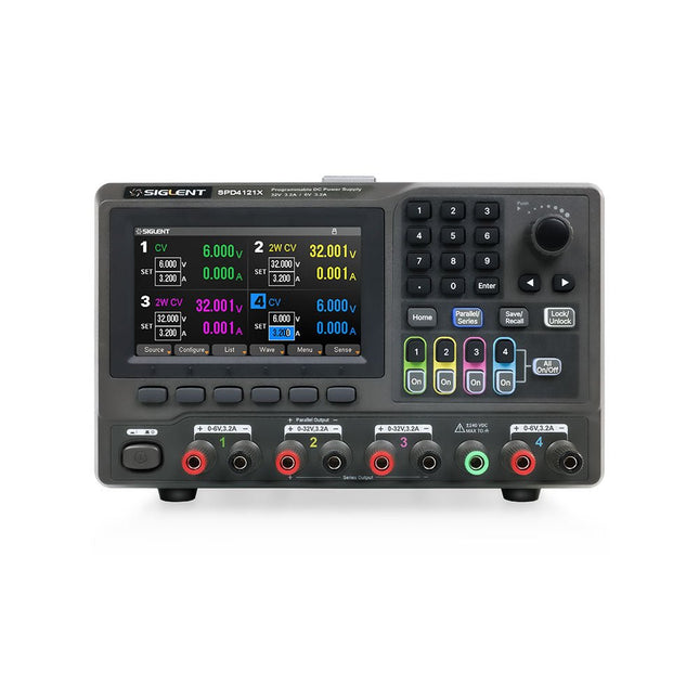
Siglent Siglent SPD4121X 4-Kanal Netzteil (285 W)
The Siglent SPD4121X is a 4-channel DC Linear Programmable Power Supply equipped with a 4.3-inch TFT-LCD display, friendly human-machine interface, and excellent performance indicators. Real-time waveform display provides engineers with an informative user interface. SPD4121X offers a total output power of 285 W with a resolution of 1 mV/1 mA. The maximum voltage and current for each channel are as follows: CH1: 15 V/1.5 A CH2: 12 V/10 A CH3: 12 V/10 A CH4: 15 V/1.5 A Features Rated output power: 285 W Rated voltage: 32 V, 12 V, 30 V Up to four high-precision power supplies with independent controllable outputs, supporting CH2 and CH3 series and parallel connections Clear graphical interface with waveform and timer display modes 5-digit voltage and current display with minimum resolution of 1 mV, 1 mA Fast output response time: <50us The high current channel support remote voltage compensation sense function. The maximum compensation voltage is 0.6 V Overvoltage protection and overcurrent protection or safe and accurate operation Equipped with a 4.3-inch TFT-LCD display (480 x 272 resolution) USB and LAN standard communication USB-GPIB module is optional Excellent channel density with up to 4 channels in a 3U half rack package Internal data storage for setups and parameters Embedded Web Server with instrument communication that doesn’t require software installation Fully SCPI programming command set support as well as a LabView driver for remote control and system automation Technische Daten SPD4323X SPD4121X SPD4306X Channel Output CH1: Voltage 0 to 6 V Current 0 to 3.2 ACH2: Voltage 0 to 32 V Current 0 to 3.2 ACH3: Voltage 0 to 32 V Current 0 to 3.2 ACH4: Voltage 0 to 6 V Current 0 to 3.2 A CH1: Voltage 0 to 15 V Current 0 to 1.5 ACH2: Voltage 0 to 12 V Current 0 to 10 ACH3: Voltage 0 to 12 V Current 0 to 10 ACH4: Voltage 0 to 15 V Current 0 to 1.5 A CH1: Voltage 0 to 15 V Current 0 to 1.5 ACH2: Voltage 0 to 30 V Current 0 to 6 ACH3: Voltage 0 to 30 V Current 0 to 6 ACH4: Voltage 0 to 15 V Current 0 to 1 A Resolution 1 mV, 1 mA 1 mV, 1 mA 1 mV, 1 mA Setting Accuracy Voltage: ±(0.03% of reading+10) mV, Current: ±(0.3% of reading+10) mA Voltage: ±(0.03% of reading+10) mV, Current: ±(0.3% of reading+10) mA Voltage: ±(0.03% of reading+10) mV, Current: ±(0.3% of reading+10) mA Readback Accuracy Voltage: ±(0.03% of reading+10) mV, Current: ±(0.3% of reading+10) mA Voltage: ±(0.03% of reading+10) mV, Current: ±(0.3% of reading+10) mA Voltage: ±(0.03% of reading+10) mV, Current: ±(0.3% of reading+10) mA Display 4.3" TFT-LCD 5-digit voltage and current display 4.3" TFT-LCD 5-digit voltage and current display 4.3" TFT-LCD 5-digit voltage and current display Output power 240 W 285 W 400 W Lieferumfang 1x Siglent SPD4121X Power Supply 1x Power cord (EU) 1x Output test cord (3 A) 1x USB cable 1x Quick start guide Downloads Datasheet Manual Quick start
€ 871,20
Bestpreis
-

Raspberry Pi Foundation FPC Kamera-Kabel für Raspberry Pi 5 (300 mm)
Der Raspberry Pi 5 verfügt über zwei vierspurige MIPI-Anschlüsse, von denen jeder entweder eine Kamera oder ein Display unterstützen kann. Diese Anschlüsse verwenden dasselbe 22-polige "Mini"-FPC-Format mit 0,5 mm Raster wie das Compute Module Development Kit und erfordern Adapterkabel für den Anschluss an die 15-poligen "Standard"-Anschlüsse mit 1 mm Raster an aktuellen Raspberry Pi Kamera- und Display-Produkten. Diese Mini-zu-Standard-Adapterkabel für Kameras und Displays (beachten Sie, dass ein Kamerakabel nicht mit einem Display verwendet werden sollte und umgekehrt) sind in den Längen 200 mm, 300 mm und 500 mm erhältlich.
€ 2,95€ 1,18Bestpreis
-

Elektor Bundles 555 Timer Projects (Bundle)
This bundle is all about designing projects based on the 555 timer IC. The book features over 45 fully tested and documented projects. Together with the kit, which contains more than 130 through-hole components, you can build all the projects described on a breadboard. The setup also makes it easy to modify and experiment with the projects. Over 45 Builds for the Legendary 555 Chip (and the 556, 558) Some of the projects in the book are: Alternately Flashing Two LEDs Changing LED Flashing Rate Touch Sensor On/Off Switch Switch On/Off Delay Light-Dependent Sound Dark/Light Switch Tone Burst Generator Long Duration Timer Chasing LEDs LED Roulette Game Traffic Lights Continuity Tester Electronic Lock Switch Contact Debouncing Toy Electronic Organ Multiple Sensor Alarm System Metronome Voltage Multipliers Electronic Dice 7-Segment Display Counter Motor Control 7-Segment Display Dice Electronic Siren Various Other Projects Kit Contents Resistors 1x 15 kΩ 1x 68 kΩ 2x 47 kΩ 1x 82 kΩ 2x 820 Ω 1x 8.2 kΩ 3x 10 kΩ 1x 1.8 kΩ 1x 6.8 kΩ 14x 2.2 kΩ 10x 680 Ω 1x 27 kΩ 1x 5.6 kΩ 1x 560 kΩ 1x 4.7 kΩ 1x 3.3 kΩ 3x 33 kΩ 1x 36 kΩ 2x 100 kΩ 5x 1 kΩ 1x 3.9 kΩ 2x 56 kΩ 2x 12 kΩ 1x 10 kΩ potentiometer 1x 1 MΩ potentiometer 2x 50 kΩ potentiometer 3x 20 kΩ potentiometer 1x 10 kΩ potentiometer 1x 10 kΩ potentiometer 1x 50 kΩ potentiometer 1x 100 kΩ potentiometer 1x 50 kΩ potentiometer Capacitors 1x 0.33 μF 1x 1 μF 1x 10 nF 1x 22 nF 1x 47 nF 1x 100 nF 1x 10 μF electrolytic 1x 33 μF electrolytic 2x 100 μF electrolytic LEDs 10x 5 mm red LED 10x 3 mm red LED 3x 3 mm yellow LED 3x 3 mm green LED 1x Common-cathode 7-segment LED Semiconductors 3x 555 timer 1x CD4017 counter 1x CD4026 counter 1x CD4011 NAND gate 4x 1N4148 diode 1x IRFZ46N MOSFET 1x Thermistor 1x Light dependent resistor (LDR) Miscellaneous 1x Passive buzzer 1x Active buzzer 1x SG90 servo 1x 8 Ω mini loudspeaker 1x 9 V DC brushed motor 1x 5 V relay 1x 9 V battery clip 7x Pushbutton switches 1x Breadboard 1x Breadboard jumper wires
€ 69,95€ 54,95Bestpreis
-

Andonstar Andonstar AD407 7" HDMI Digital-Mikroskop
Untersuchen Sie Ihre Schaltkreise mit hoher Präzision und löten Sie auch kleinste SMDs und Bauteile problemlos! Features Das multifunktionale digitale HDMI-Mikroskop bietet Full HD, komfortable Kopffreiheit, verbesserte Ergonomie und mehrere Ausgangssignale mit unterschiedlichen Auflösungen. Der Neigungswinkel des breiten LCD-Monitors ist einstellbar. Fernbedienung im Lieferumfang inbegriffen. Kann als eigenständiges Gerät verwendet werden. Technische Daten Bildschirmgröße 7 Zoll (17,8 cm) Bildsensor 4 MP Videoausgang UHD 2880x2160 (24fps)FHD 1920x1080 (60fps/30fps)HD 1280x720 (120fps) Videoformat MP4 Vergrößerung Bis zu 270-fach (27" HDMI-Monitor) Bildauflösung Max. 12 MP (4032x3024) Bildformat JPG Fokusbereich Min. 5 cm Bildrate Max. 120fps (unter 600 Lux Helligkeit & HDP120) Videoschnittstelle HDMI Speichermedium microSD-Karte (bis zu 32 GB) Stromversorgung 5 V DC Beleuchtung 2 LEDs mit Standfuß Abmessungen 20 x 12 x 19 cm Lieferumfang 1x Andonstar AD407 Digital-Mikroskop 1x Metallstativ mit 2 LEDs 1x Optische Halterung 1x UV-Filter 1x IR-Fernbedienung 1x Schalterkabel 1x Netzadapter 1x HDMI-Kabel 2x Schrauben 1x Schraubendreher 1x Handbuch Downloads Manual Modellvergleich AD407 AD407 Pro AD409 AD409 Pro-ES Bildschirmgröße 7 Zoll (17,8 cm) 7 Zoll (17,8 cm) 10,1 Zoll (25,7 cm) 10,1 Zoll (25,7 cm) Bildsensor 4 MP 4 MP 4 MP 4 MP Videoausgang 2160p 2160p 2160p 2160p Schnittstellen HDMI HDMI USB, HDMI, WiFi USB, HDMI, WiFi Videoformat MP4 MP4 MP4 MP4 Vergrößerung Bis zu 270x Bis zu 270x Bis zu 300x Bis zu 300x Bildauflösung Max. 4032x3024 Max. 4032x3024 Max. 4032x3024 Max. 4032x3024 Bildformat JPG JPG JPG JPG Fokusabstand Min. 5 cm Min. 5 cm Min. 5 cm Min. 5 cm Bildrate Max. 120f/s Max. 120f/s Max. 120f/s Max. 120f/s Speichermedium microSD-Karte microSD-Karte microSD-Karte microSD-Karte PC-Unterstützung Nein Nein Windows Windows Mobile Konnektivität Nein Nein WiFi + Messung WiFi + Messung Stromversorgung 5 V DC 5 V DC 5 V DC 5 V DC Beleuchtung 2 LEDs mit Standfuß 2 LEDs mit Standfuß 2 LEDs mit Standfuß 2 LEDs mit Standfuß Endoskop Nein Nein Nein Ja Abmessungen 20 x 12 x 19 cm 20 x 18 x 32 cm 18 x 20 x 30 cm 18 x 20 x 32 cm Gewicht 1,6 kg 2,1 kg 2,2 kg 2,5 kg
€ 182,07
-

Elektor Labs Elektor Super Servo Tester Kit
Der Elektor Super Servo Tester kann Servos steuern und Servosignale messen. Es können bis zu vier Servokanäle gleichzeitig getestet werden. Der Super Servo Tester wird als Bausatz geliefert. Alle zum Zusammenbau des Super Servo Testers erforderlichen Teile sind im Bausatz enthalten. Für den Zusammenbau des Bausatzes sind grundlegende Lötkenntnisse erforderlich. Der Mikrocontroller ist bereits programmiert. Der Super Servo Tester verfügt über zwei Betriebsmodi: Steuerung/Manuell und Messen/Eingänge. Im Control/Manual Modus generiert der Super Servo Tester an seinen Ausgängen Steuersignale für bis zu vier Servos oder für den Flugregler oder ESC. Die Signale werden über die vier Potentiometer gesteuert. Unter Measure/Inputs misst der Super Servo Tester die an seine Eingänge angeschlossenen Servosignale. Diese Signale können beispielsweise von einem Regler, einem Flugregler, dem Empfänger oder einem anderen Gerät stammen. Die Signale werden auch an die Ausgänge weitergeleitet, um die Servos oder den Flugregler bzw. ESC zu steuern. Die Ergebnisse werden auf dem Display angezeigt. Technische Daten Betriebsmodi Control/Manual & Measure/Inputs Kanäle 3 Servosignaleingänge 4 Servosignalausgänge 4 Alarm Summer & LED Anzeige 0,96' OLED (128 x 32 Pixel) Eingangsspannung an K5 7-12 VDC Eingangsspannung an K1 5-7,5 VDC Eingangsstrom 30 mA (9 VDC an K5, nichts an K1 und K2 angeschlossen) Abmessungen 113 x 66 x 25 mm Gewicht 60 g Lieferumfang Widerstände (0,25 W) R1, R3 1 kΩ, 5% R2, R4, R5, R6, R7, R9, R10 10 kΩ, 5% R8 22 Ω, 5% P1, P2, P3, P4 10 kΩ, lin/B, vertikales Potentiometer Kondensatoren C1 100 µF 16 V C2 10 µF 25 V C3, C4, C7 100 nF C5, C6 22 pF Halbleiter D1 1N5817 D2 LM385Z-2.5 D3 BZX79-C5V1 IC1 7805 IC2 ATmega328P-PU, programmiert LED1 LED, 3 mm, rot T1 2N7000 Außerdem BUZ1 Piezo-Summer mit Oszillator K1, K2 2-reihiger, 12-poliger Pinheader, 90° K5 Barrel jack K4 1-reihige, 4-polige Stiftbuchse K3 2-reihiger, 6-fach geschachtelter Pinheader S1 Slide Switch DPDT S2 Slide Switch SPDT X1 Crystal, 16 MHz 28-polige DIP-Buchse für IC2 Elektor Platine OLED-Display, 0,96', 128 x 32 Pixel, 4-pin I²C-Interface Links Elektor Magazine Elektor Labs
€ 59,95€ 49,95Bestpreis
-

Elektor Academy Pro Arduino (Programmierkurs)
Dieser komplette Mikrocontroller-Programmierkurs auf Basis des Arduino Uno umfasst ein Lehrbuch, ein Komponenten-Kit, praxisnahe Projekte sowie einen umfassenden Online-Kurs mit Simulationen. Er eignet sich ideal für das schrittweise Erlernen der Embedded-Programmierung mit Arduino anhand eines praktischen, hands-on Ansatzes. Eine praxisnahe Einführung in Embedded Systems mit dem Arduino Uno Dieser Kurs richtet sich an Personen ohne Vorkenntnisse im Bereich Embedded Systems, die einen strukturierten und beispielbasierten Einstieg suchen. Ein Kit bestehend aus LEDs und Widerständen, Schaltern, Sensoren und Aktoren, Displays, einem Breadboard und Kabeln sowie weiteren Komponenten ist enthalten. Diese werden im Kurs verwendet, um Beispielanwendungen zu veranschaulichen. Vorkenntnisse mit Arduino oder Embedded-Entwicklung sind nicht erforderlich. Jeder Abschnitt enthält praktische Beispiele und Mini-Projekte, die wichtige Konzepte festigen und zur weiteren Vertiefung anregen. Am Ende des Kurses werden Sie nicht nur in der Lage sein, die Beispiele nachzuvollziehen, sondern auch eigene Ideen und Anwendungen umzusetzen. Was werden Sie lernen? Mikrocontroller-Programmierung mit Arduino unter Verwendung des Uno R3 Boards Arbeiten mit digitalen Ein- und Ausgängen, Auslesen von Tastern und Encodern, Steuern von LEDs und Relais Auslesen analoger Eingänge, Spannungen und analoger Sensoren Erzeugung analoger Ausgangssignale und PWM Verwendung serieller Kommunikation wie UART, I²C und SPI zur Steuerung von Displays und zum Auslesen digitaler Sensoren und SD-Karten Zeitmanagement Arbeiten mit Interrupts Echtzeit-Sensordatenerfassung und Steuerung über Taster, LEDs und Displays Steuerung von Aktoren wie Relais und Servomotoren Für wen ist dieser Kurs geeignet? Studierende und Selbstlerner im Bereich Embedded Systems Makers und IoT-Enthusiasten, die ihre Hardware-Kenntnisse verbessern möchten Lehrkräfte und Trainer, die sofort einsetzbares Unterrichtsmaterial suchen Was ist im Lieferumfang enthalten? Zugang zum vollständigen Kurs auf der Elektor Academy Pro-Lernplattform Uno R3 Mikrocontroller-Board (+ USB-Kabel) Buch: Programming Microcontrollers in C/C++ Using Arduino Downloadbare Projektdateien für jedes Modul Komponenten-Set: 2× LED, rot, 5 mm LED, grün, 5 mm 3× Widerstand, 470 Ω, 0,25 W LDR Potentiometer, 10 kΩ, linear Taster Drehencoder-Modul Relaismodul DHT22 Feuchtigkeits- und Temperatursensor TM1637-kompatibles 4-stelliges 7-Segment-Display MPU-6050 IMU mit Stiftleisten SSD1306-kompatibles I²C OLED-Display Micro-SD-Kartenadapter mit Stiftleiste Buzzer SG90 Mikro-Servo ILI9341-kompatibles SPI 240×320 TFT-Display 20× Jumperkabel Breadboard Alle Programmierkurse (und Unterschiede im Inhalt) Kurs Arduino Raspberry Pi Pico with Arduino C/C++ ESP32 with Arduino C/C++ Raspberry Pi Pico with MicroPython ESP32 with MicroPython Online-Kurs Access to Arduino Course Access to Pico with Arduino C/C++ Course Access to ESP32 with Arduino C/C++ Course Access to Pico with MicroPython Course Access to ESP32 with MicroPython Course Board Uno R3 Raspberry Pi Pico ESP32 Raspberry Pi Pico ESP32 Buch Programming Microcontrollers in C/C++ Using Arduino Programming Microcontrollers in C/C++ Using Arduino Programming Microcontrollers in C/C++ Using Arduino Programming Microcontrollers in MicroPython Programming Microcontrollers in MicroPython Kit 40-teiliges Komponenten-Set 40-teiliges Komponenten-Set 40-teiliges Komponenten-Set 40-teiliges Komponenten-Set 40-teiliges Komponenten-Set
€ 69,95
Mitglieder: € 62,96
-

Elektor Digital The EAGLE Companion (E-book)
EAGLE – the “Easily Applicable Graphical Layout Editor“ is a professional-grade CAD (computer aided design) software package for the design and drafting of electronic schematics as well as the design and fabrication of printed circuit boards (PCBs). This Advanced User Guide provides the experienced EAGLE user with insight into using some of the more advanced features of EAGLE software. It is not a guide to teach the reader the basic concepts of EAGLE, nor does it discuss the ‘how to’ of the EAGLE interface and the simpler operations and commands of the software. That is the purpose of the author’s previous title EAGLE V6 Getting Started Guide also published by Elektor. This eBook is intended as an enduring document covering the more advanced modules, commands, and functions which make up EAGLE. It is hoped that this eBook will provide a quick, succinct reference to assist with more complex applications and uses of EAGLE – an ‘EAGLE User’s Companion’, if you like. Complementing the EAGLE Advanced User Guide, the EAGLE User Language manual is included in this eBook in unabridged form, reproduced with permission of CadSoft GmbH. At the time of writing, the material in this eBook covers version 7 of the EAGLE software suite.
€ 39,95
Mitglieder: € 35,96
-

Siglent Siglent SPD4306X 4-Kanal Netzteil (400 W)
The Siglent SPD4306X is a 4-channel DC Linear Programmable Power Supply equipped with a 4.3-inch TFT-LCD display, friendly human-machine interface, and excellent performance indicators. Real-time waveform display provides engineers with an informative user interface. SPD4306X offers a total output power of 400 W with a resolution of 1 mV/1 mA. The maximum voltage and current for each channel are as follows: CH1: 15 V/1.5 A CH2: 30 V/6 A CH3: 30 V/6 A CH4: 15 V/1 A Features Rated output power: 400 W Rated voltage: 32 V, 12 V, 30 V Up to four high-precision power supplies with independent controllable outputs, supporting CH2 and CH3 series and parallel connections Clear graphical interface with waveform and timer display modes 5-digit voltage and current display with minimum resolution of 1 mV, 1 mA Fast output response time: <50us The high current channel support remote voltage compensation sense function. The maximum compensation voltage is 0.6 V Overvoltage protection and overcurrent protection or safe and accurate operation Equipped with a 4.3-inch TFT-LCD display (480 x 272 resolution) USB and LAN standard communication USB-GPIB module is optional Excellent channel density with up to 4 channels in a 3U half rack package Internal data storage for setups and parameters Embedded Web Server with instrument communication that doesn’t require software installation Fully SCPI programming command set support as well as a LabView driver for remote control and system automation Technische Daten SPD4323X SPD4121X SPD4306X Channel Output CH1: Voltage 0 to 6 V Current 0 to 3.2 ACH2: Voltage 0 to 32 V Current 0 to 3.2 ACH3: Voltage 0 to 32 V Current 0 to 3.2 ACH4: Voltage 0 to 6 V Current 0 to 3.2 A CH1: Voltage 0 to 15 V Current 0 to 1.5 ACH2: Voltage 0 to 12 V Current 0 to 10 ACH3: Voltage 0 to 12 V Current 0 to 10 ACH4: Voltage 0 to 15 V Current 0 to 1.5 A CH1: Voltage 0 to 15 V Current 0 to 1.5 ACH2: Voltage 0 to 30 V Current 0 to 6 ACH3: Voltage 0 to 30 V Current 0 to 6 ACH4: Voltage 0 to 15 V Current 0 to 1 A Resolution 1 mV, 1 mA 1 mV, 1 mA 1 mV, 1 mA Setting Accuracy Voltage: ±(0.03% of reading+10) mV, Current: ±(0.3% of reading+10) mA Voltage: ±(0.03% of reading+10) mV, Current: ±(0.3% of reading+10) mA Voltage: ±(0.03% of reading+10) mV, Current: ±(0.3% of reading+10) mA Readback Accuracy Voltage: ±(0.03% of reading+10) mV, Current: ±(0.3% of reading+10) mA Voltage: ±(0.03% of reading+10) mV, Current: ±(0.3% of reading+10) mA Voltage: ±(0.03% of reading+10) mV, Current: ±(0.3% of reading+10) mA Display 4.3" TFT-LCD 5-digit voltage and current display 4.3" TFT-LCD 5-digit voltage and current display 4.3" TFT-LCD 5-digit voltage and current display Output power 240 W 285 W 400 W Lieferumfang 1x Siglent SPD4306X Power Supply 1x Power cord (EU) 1x Output test cord (3 A) 1x USB cable 1x Quick start guide Downloads Datasheet Manual Quick start
€ 1.101,10
Bestpreis


