
Suchergebnisse für "squink OR multilayer OR pcb OR printer"
-

Elektor Digital Elektor March/April 2021 (PDF) EN
The Vision and Engineering Behind SparkFun Getting Started with MicroMod Leveling Up Your SparkFun JetBotHow I Expanded the Functionality of My JetBot, Powered by the NVIDIA Jetson Nano Programming an FPGA How to Build a DIY GNSS Reference Station The ClockClock Project Under the Hood: SparkFun Inventor's Kit SparkFun’s Glenn Samala on Product Development and New Ventures Creating Custom Circuit Boards with SparkFun À La Carte Designing with the SparkFun Artemis Getting Started with the Qwiic Ecosystem for Rapid Prototyping Poster - Qwiic Under the Hood: The GreatScott! / Elektor DIY LiPo Supercharger Kit Memorable Electronics from SparkFun Past Perfect Parking with LiDAR Buried Pad PCB Fixing Design to Sale: the SparkFun RTK Surveyor Hello World from the Raspberry Pi Pico and RP2040A Look at Raspberry Pi’s First Microcontroller and Microcontroller Chip DIY Quadrupedal Robots Poster - Micromod RISC-V IoT Development in AWS Using FreeRTOS Libraries Yep, Electronics = Fun!A Conversation Among Electronics Enthusiasts Sparkfun Product Catalog HexadokuThe Original Elektorized Sudoku
€ 7,50
-

Elektor Digital Elektor Septembre/Octobre 2026 (PDF) FR
Le téléchargement intégral de ce numéro est disponible pour nos membres GOLD et GREEN sur le site Elektor Magazine ! Pas encore membre ? Cliquez ici. l'ESP-BLASTUn mini drone-fusée ESP32 qui vole à plus de 100 km/h atelier sans fil (1)Modules radio déverrouillés : émetteur-récepteur sub-GHz CC1101 433 MHz émetteur AMAvec le générateur d'ondes carrées/sinusoïdales sur Raspberry Pi Pico STM32Cube Innovation ChallengeParticipez avec votre meilleur projet STM32C5 CoffeeCallerComment une pause café a inspiré un PCB sur mesure audiotroniquesDistorsion harmonique totale Elektor à 65 ansProjets de septembre et octobre au fil des ans Bluetooth Channel Sounding pour le suivi des équipementsMesure de distance avec une précision centimétrique pour l’IoT de nouvelle génération 2026 : une Odyssée de l'IAL'informatique quantique n'est pas le prochain GPU protéger le cloud exige de sécuriser la périphérie premières expériences avec le HackRF ProTests pratiques avec le nouveau matériel SDR mise à niveau du modem de GPRS/2G vers LTE/4GExemple d'un panneau de contrôle d'alarme sans fil antenne en bouclePartie 1 : Une antenne ondes courtes à directivité réglable, à réaliser soi-même convertisseur de radio Internet en AMUn ESP32-S3 comme émetteur projet 2.0 mioty : aperçu généralL'approche de Fraunhofer pour les LPWAN sagesse d'atelierConseils pratiques d'experts Walter, le module IoT compactPartie 2 : Accéder aux services météorologiques et aux services de données
€ 10,95
-

Zhongdi ZD-11E Platinenhalter
Dieser verstellbare Platinenhalter ist ideal zum Klemmen von Platinen zum Löten, Entlöten oder Nacharbeiten. Fetaures 2 verstellbare Griffe auf einem einziehbaren Ständer für verschiedene Boardgrößen. Die verstellbaren Klemmen ermöglichen es der Leiterplatte, sich um 360 Grad zu drehen und in jeder Position zu bleiben. Die Grundplatte dieses starren Metallständers verfügt über vier Gummifüße, um Stabilität zu gewährleisten. Technische Daten Produktgröße 30 x 16,5 x 12,5 cm Max. Größe der Halterung 20 x 14 cm Gewicht 450 g
€ 7,82
-

Elektor Publishing Professional SMD Assembly
Practical Low-Cost Methods for Reliable PCB Production This book explains how to carry out reliable SMD assembly using affordable tools and small-scale equipment. It follows the complete workflow step by step, including tool selection, solder paste handling, stencil use, component placement, reflow methods, inspection, and rework. The focus is on bench-level and small-lab production rather than industrial assembly lines. It shows practical methods for building single and double-sided SMD boards with repeatable results. Topics include solder paste and flux, temperature profiles, hot air and hotplate techniques, small reflow ovens, inspection methods, and defect correction. Checklists and example workflows are included to help reduce errors and improve consistency. Key features: Tools and supplies for SMD assembly and rework Solder paste types, storage, and handling Stencils and paste application methods Pick and place workflow and component orientation Temperature profiles and reflow methods Hot air, hotplate, and reflow oven processes Inspection and quality control Common defects such as tombstoning and solder bridges Practical rework and component replacement Bench-level professional workflows and checklists This book is designed as a practical bench reference for anyone who wants to assemble and troubleshoot their own SMD boards with reliable results.
€ 24,95
Mitglieder: € 22,46
-

Elektor Labs Elektor Rauscharmes Labornetzteil
Das rauscharme Labornetzteil von Elektor ist ein vollständig analoges, einstellbares, symmetrisches Gerät mittlerer Leistung, das ohne Schalt- oder digitale Komponenten auskommt. Es bietet eine Ausgangsspannung, die zwischen 0 V und ±22 V einstellbar ist, sowie einen Ausgangsstrom, der von 0 A bis 1 A eingestellt werden kann. Da auf jegliche Art von Schalttechnik verzichtet wird, liefert das Design extrem geringes Rauschen. Zur Anzeige beider Ausgangsspannungen und -ströme werden vier kleine analoge Einbauinstrumente mit Drehspulmesswerk verwendet. Die meisten modernen Labornetzgeräte und AC-Adapter arbeiten mit Schaltnetzteiltechnik. Selbst die besten Ausführungen weisen zwangsläufig hochfrequente Restwelligkeit und andere Schaltartefakte am Ausgang auf, die die Prüfung empfindlicher analoger Schaltungen stören und Messungen kleiner Signale beeinträchtigen können. Um dieses Problem zu vermeiden, setzt dieses Konzept auf ein vollständig analoges Netzgerät. Obwohl es weniger effizient ist als vergleichbare Schaltnetzteile, spielt die geringere Effizienz beim Einsatz auf dem Prüfstand kaum eine Rolle und sorgt für sauberere und zuverlässigere Messergebnisse. Da viele analoge Schaltungen eine symmetrische Versorgung benötigen, liefert dieses Design positive und negative Ausgangsspannungen gleicher Höhe. Eine geringfügige Nachjustierung ist möglich, um eventuelle Ungleichgewichte auszugleichen. Selbstverständlich ist auch eine einstellbare Strombegrenzung integriert. Das Kit enthält die für den Aufbau des Netzteils erforderlichen Komponenten, mit Ausnahme der Transformatoren. Technische Daten Ausgangsspannung 0…+22 V, 0, −22 V Ausgangsstrom 0…+1 A, 0…−1 A Rauschen −85 dBV (bei 0,95 A/20 V, B = 22 kHz) −84 dBV (bei 0,95 A/20 V, B > 500 kHz) Restwelligkeit 50 µVRMS (bei 950 mA/20 V, B = 22 kHz, hauptsächlich 100-Hz-Anteil) Lieferumfang 3x Platinen: Regler (PCB-1), Netzfilter (PCB-2) und Transformator (PCB-3) Alle Bauteile mit Ausnahme der Netztransformatoren 4x Drehspulmesswerke Zusätzliche Teile für die Verdrahtung (Drähte, Bananenbuchsen, Kaltgeräte-Netzmodul usw.) Nicht enthalten Die drei Netztransformatoren Ein Gehäuse Stückliste Für die Spannungsregler-Platine (240386-1) Widerstände (250 mW, 1%) R1 = 12 Ω R2, R8, R37, R62 = 1 MΩ R3, R7, R10, R13, R17, R20, R22, R30, R35, R42, R45, R47, R55, R60 = 100 Ω, 600 mW R4, R5 = 4.7 kΩ R6 = 100 kΩ R9, R12, R14, R36, R38, R39, R61, R63, R66, R72, R78, R79 = 10.0 kΩ, 600 mW R11 = 9.76 kΩ, 600 mW R15, R40 = 44.2 kΩ, 600 mW R16, R41, R77 = 1 kΩ R18, R43 = 1.5 kΩ, 1 W, 5% R19, R44 = 470 Ω, 1 W, 5% R21, R46 = 330 Ω, 600 mW R23, R24, R48, R49 = 1.0 Ω, 1 W R25, R50 = 1 kΩ, 1 W, 5% R26, R28, R51, R53 = 1.000 kΩ 0.1%, 15 ppm/C R27, R29, R52, R54 = 10.00 kΩ 0.1%, 15 ppm/C R31, R56 = 1.2 kΩ, 1 W, 5% R32, R57 = 47 kΩ R33, R58 = 270 Ω R34, R59 = 27 kΩ R64, R69 = 12.0 kΩ R65 = 3.0 kΩ, 600 mW R67, R80 = 470 Ω, 600 mW R68, R70 = 6.8 kΩ, 600 mW R71 = 30.0 kΩ,, 600 mW R73, R74, R75, R76 = 10 MΩ P1, P2, P3 = 10 kΩ, 200 mW, 20%, potentiometer, 1 turns, single, lin., panel mount P4, P5 = 500 Ω, 500 mW, 10%, trimmer, 25 turns, 3296Y-1-501LF Bourns P6, P7 = 10 kΩ, 500 mW, 10%, trimmer, 25 turns, 3296Y-1-501LF Bourns Kondensatoren C1 = 100 nF, 50 V, 10%, ceramic X7R, LS 5 mm C2, C3, C6, C7, C30 = 10 µF, 63V, 20%, LS 2.5 mm, 3000hours@105°C C4, C5, C8, C9, C13, C14, C18, C19, C23, C24, C28, C29, C31, C32, C38, C39 = 100 nF, 250 V, 10%, PET, LS 7.5 mm C10, C20 = 47 nF, 100 V, 5%, PET, LS 5 mm C11, C21 = 10 nF, 100 V, 5%, PET, LS 5 mm C12, C22 = 220 µF, 35 V, 20%, 0.024 Ω, LS2.5/3.5 mm, Ir 3.4 A, 2000hours@125°C, polymer C15, C25 = 120 µF, 50 V, 20%, ESR 0.02 Ω, Diam. 10 mm max., LS 5 mm C16, C26 = 15 nF, 100 V, 5%, PET, LS 5 mm C17, C27 = 47 nF, 100 V, 5%, PET, LS 5 mm C33, C34 = 22 µF, 50 V, 20%, LS 2 mm, 10000 hours @ 105°C C35, C36, C44, C45 = 1 µF, 100 V, 10%, LS 5 mm, ceramic X7R C37 = 100 uF, 50 V, 20%. LS 3.5 mm C40, C41, C42, C43, C46, C47, C48, C49 = 1000 µF, 50 V, 20%, LS 5/7.5 mm, Ir 3.32 A, 10000hours@105°C, D 16 mm C50, C51, C52, C53 = 47 nF, 100 V, 10%, ceramic X7R, LS 5 mm Induktivitäten L1, L2 = 4.7 µH, 3.2 A, 0.033 Ω, LS 5 mm, RLB0914-4R7ML Bourns L3 = Commom mode choke, 14.5 mH, 3 A, SSRH24NH-30145 Kemet Halbleiter D1, D2, D3, D4, D5, D9, D10, D11, D15 = BAT85, DO-34 D6, D7, D12, D13 = SR560, DO-201AD D8, D14, D16 = 1N4148, DO-35 D17 = Zenerdiode, 5.6 V, 0.5 W, DO-41 D18, D19 = 1N4004, DO-41 D20, D21 D22, D23 = V30100CI-M3/P, dual common cathode, TO-220 D24 = Zener diode, 30 V, 1 W, DO-41 LED1, LED2 = LED, red, T-1 (3 mm) LED3, LED4 = LED, green, T-1 (3 mm) TVS1, TVS2 = BZW50-33B, R6 T1, T2, T4 = BC337.25, TO-92 T3 = NJW0302G, TO-3P T5, T6, T8 = BC327.25, TO-92 T7 = NJW0281G, TO-3P T9 = BD139, TO-126 (SOT-32) IC1 = LM334Z, TO-92 IC2 = LM4040AIZ-5.0/NOPB, TO-92 (TO-226AA-3) IC3, IC4 = OPA2992IDR, SOIC-8 IC5, IC6 = OPA4992IDR, SOIC-14 IC7 = OPA992IDBVR, SOT-23-5 IC8 = LM339N, DIP-14 IC9 = LM317, TO-220 IC10 = LM337, TO-220 Sonstiges F1, F2 = 5×20 mm fuse, 1.6 A, fast acting HS1, HS2 = Heatsink MC33271 (for T3/T7), 2.7°C/W, PCB mount, height 63.5 mm K1, K4 = 3-way screw terminal block, LS 3.5 mm, max. 1.5 mm² K2, K3 = 3-way screw terminal block, LS 3.5 mm, max. 1 mm² M1, M3 = Moving coil meter, Range 30 V, type 91C4, 45×45 mm M2, M4 = Moving coil meter, Range 1 A, type 91C4, 45×45 mm² RE1 = Relay DPDT,5V, UA2-5NU Verschiedenes 3× 3-way screw terminal block, LS 3.5 mm, max. 1 mm² (for P1, P2, P3) 4× Pin header, 1×2, vertical, pitch 2.54 mm (for LED1, LED2, LED3, LED4) 4× Pin socket, 1×2, vertical. pitch 2.54 mm (for LED1, LED2, LED3, LED4) 2× Heatsink FK222SA220, 20°C/W, PCB mount (for IC9 & IC10) 2× Mica thermal pad for TO-220, 12×18×0.05 mm (for IC9 & IC10) 2× Insulating bushing IB 6, TO-220 (for IC9 & IC10) 2× Ceramic thermal pad, 23×20×2 mm (for T3 & T7) 2× PCB Fuse Holder, for 5×20 mm fuse, 10 A (for F1, F2) 2× Cover for PCB Fuse Holder, transparent (for F1, F2) 2× 2-way screw terminal block, LS 3.5 mm, max. 1 mm² (for M1 & M3) 2× 2-way screw terminal block, LS 3.5 mm, max. 1.5 mm² (for M2 & M4) 8× M3 solder lug, thickness 0.35 mm (for M1…M4) M4 solder lug, thickness 0.35 mm (to connect 4 mm banana connectors) Screened cable, 1 pair, 2×24 AWG/0.22 mm², 1 m (for P1, P2 & P3) IC socket, DIP, 14 contacts (for IC8) M3 washer, plain, steel M3 screw, 16 mm, steel, pan head M3 nut M3 spring washer 50 mm M3 standoff, steel, male-female 12 mm M3 standoff, steel, male-female 10 mm M3 standoff, steel, male-female M3 screw, 8 mm, steel, pan head Für die Netzfilter-Platine (240386-2) Widerstand R1 = 220 kΩ, 1 W, 500 V, 5% Kondensatoren C1, C2 = 470 nF, 305 VAC, Class X2, 11 × 27 mm max., LS 15/22.5 mm C3, C4, C5, C6 = 2.2 nF, 300 VAC, Class Y2, 13 × 4 mm, LS 10 mm, PP Induktivitäten L1, L2 = Common-mode choke, 6.8 mH, 1.7 A, TDK B82732R2172B030 Halbleiter MOV1 = TVS varistor, 300 VAC, S14K300 (230 VAC, B72214S0301K101) and SK14K150 (150 VAC, B72214S0151K101) Sonstiges K1, K2 = 3-way screw terminal block, LS 7.62 mm F1 = Time-delay fuse, 0.5 A (230 VAC) or 1 A (115 VAC) Verschiedenes 1× Fuse holder, 5×20 mm, 10 A, 500 VAC 1× Transparent fuse cover 4× 10 mm M3 standoff, steel, male–female 4× M3 screw, 8 mm, steel, pan head 4× M3 nut Für die Transformator-Platine (240386-3) Widerstände R1, R2 = 2.7 kΩ, 600 mW, 1% R3 = 10.0 kΩ, 600 mW, 1% Kondensator C1 = 220 µF, 50 V, 20%, Ø10 mm, LS 5 mm, 4000 h @ 105°C Transformatoren (nicht im Lieferumfang dieses Kits enthalten!) TR1, TR2, TR3 = 2×7 V, 25 VA, PCB-mounted toroid, 70060K Talema Halbleiter D1–D4 = 1N4148, DO-35 D5, D6 = 1N4004, DO-41 D7 = Zener 5.6 V, 1.3 W, DO-41 LED1 = LED, red, T-1 (3 mm) IC1, IC2 = MOC8021M, CTR ≥ 1000%, DIP-6 Sonstiges F1, F2, F3 = 160 mA time-delay fuse (230 VAC) or 315 mA time-delay fuse (115 VAC) K1 = 2-way screw terminal block, LS 7.62 mm K2 = 3-way screw terminal block, LS 3.5 mm, max 1.5 mm² K3, K4 = 3-way screw terminal block, LS 3.5 mm, max 1 mm² RE1, RE2 = Relay DPDT, 5 A/250 VAC / 24 VDC Verschiedenes 1× Pin header 1×2, pitch 2.54 mm + matching socket for LED1 3× Fuse holder 5 × 20 mm, 10 A, 500 VAC + transparent cover 3× M4 screw, 8 mm, pan head + washer for TR1-TR3 8× M3 screw, 8 mm, pan head + nut + washer 8× 10 mm M3 standoff, steel, male–female 2× IC socket, DIP-6 for IC1 & IC2 Weitere Bauteile 1 m red insulated wire, stranded, 1.5 mm² 0.5 m blue insulated wire, stranded, 1.5 mm² 0.5 m black insulated wire, stranded, 1.5 mm², 0.5 m 2 m red insulated wire, stranded, D 0.56 mm (0.25 mm²) 2 m black insulated wire, stranded, D 0.56 mm (0.25 mm²) 0.5 m Multicore Cable, Flexible, 3 Core, 0.75 mm² (24 x 0.2 mm) Red banana socket Black banana socket Blue banana socket Green banana socket IEC Power Entry Module with switch, IEC C14 3 crimp terminals, FASTON, 4.75 x 0.81 mm 3 knobs Links Elektor Labs JumpStarter Page Artikel (Teil 1) Artikel (Teil 2)
€ 299,00€ 249,00Bestpreis
-

Elektor Digital KiCad Like A Pro – Fundamentals and Projects (E-book)
Getting started with the world’s best open-source PCB tool The latest iteration of KiCad, the world’s best free-to-use Printed Circuit Board tool, is packed with features usually found only in expensive commercial CAD tools. This modern, cross-platform application suite built around schematic and design editors, with auxiliary applications is a stable and mature PCB tool. KiCad 8 is a perfect fit for electronic engineers and makers. Here are the most significant improvements and features in KiCad 8, both over and under the hood: Modern user interface, completely redesigned from earlier versions Improved and customizable electrical and design rule checkers Theme editor allowing you to customize KiCad on your screen Ability to import projects from Eagle, CADSTART, and more Python scripting API Improved integrated SPICE circuit simulator Multi-sheet schematics Filters define selectable elements Enhanced interactive router helps you draw single tracks and differential pairs with precision New or enhanced tools to draw tracks, measure distances, tune track lengths, etc. Advanced interactive router Built-in bill of materials generator Realistic ray-tracing capable 3D viewer Customizable teardrops Plug-in manager for quick installation of themes, libraries and functionalities such as autorouters and BOM generators This book will teach you to use KiCad through a practical approach. It will help you become productive quickly and start designing your own boards. Example projects illustrate the basic features of KiCad, even if you have no prior knowledge of PCB design. The author describes the entire workflow from schematic entry to the intricacies of finalizing the files for PCB production and offers sound guidance on the process. Further full-fledged projects, of incremental difficulty, will be presented in a second book, together with a variety of advanced recipes.
€ 44,95
Mitglieder: € 40,46
-

Sensepeek Sensepeek 6024 SQ500 (500 MHz Freihand-Oszilloskopsonde)
Die SQ-Serie von handsfreien Sonden von Sensepeek hat aufgrund ihres niedrigeren Schwerpunkts eine noch höhere Stabilität im Vergleich zur ursprünglichen SP-Serie von handsfreien Sonden. Alle Sonden der SQ-Serie sind auch isoliert und können wie jede herkömmliche Sonde von Hand gehalten werden, aber ihr volles Potenzial wird bei handsfreier Messung genutzt. Die SQ-Serie von Oszilloskop-Sonden bietet auch mehr Erdungsoptionen, hat eine Probe-Spitzen-Schutzabdeckung, ein längeres Kabel und unterstützt Oszilloskope mit automatischer Skalierung (10:1). Alle beliebten Funktionen der handsfreien Messung, auswechselbare feinrastergefederte Testnadeln, farbcodierte Kabelhalter und das minimalistische Design bleiben erhalten, um herkömmliche und handgehaltene Sonden überflüssig zu machen. Sowohl die Länge als auch das Gewicht der SQ-Sonden sind perfekt ausbalanciert, um mit den PCBite-PCB-Haltern und der Basisplatte verwendet zu werden, die für die handsfreie Funktion unerlässlich sind. Features Passive 10:1-Sonde mit Unterstützung für Oszilloskope mit automatischer Skalierung Federbelastete Testnadel für Feinrastermessungen Mehrere Erdungsoptionen Farbcodierte Kabelhalter Probe-Spitzen-Schutzabdeckung Isoliert, kann von Hand gehalten werden Verbesserter Sondenhalter für handsfreie Messungen bei Verwendung von PCBite-PCB-Haltern Lieferumfang 1x SQ500 500 MHz Sonde mit gefederter Testnadel 1x SQ-Sondenhalter für handsfreie Messungen 1x Testhaken mit abnehmbaren Kabeln (5 cm & 10 cm) für eine bequeme Erdungsverbindung 1x Alligator-Kabel für eine bequeme Erdungsverbindung 1x Standard-Erdungsfeder für handgehaltene Messungen bei Nennbandbreite 1x Einzigartige Erdungsfeder für vollständig handsfreie Messungen bei Nennbandbreite 1x Set farbcodierter Kabelhalter (4 Farben) 1x Probe-Spitzen-Schutzabdeckung 1x Zusätzliche Testnadel Downloads Benutzerhandbuch SQXX0 Rev1.1
€ 129,71
-

Elektor Circuit Special 2026 (NL)
Elektor GREEN en GOLD leden kunnen deze uitgave hier downloaden. Nog geen lid? Klik hier om een lidmaatschap af te sluiten. Een stroombron voor het testen van Z-diodesControle van Z-diodes van 1 tot 54 V bij 1 tot 50 mA ESD polsbandtesterEen testapparaat met indicatie voor ‘goed’, ‘grensgeval’ en ‘afgekeurd’ Testapparaat voor de respons op piekbelastingen van voedingenEen generator voor repeterende stapsgewijze belasting voor laboratoriumvoedingen Euclidische sequencer zonder microcontrollerTriggerpatronen en CV-sequenties met eenvoudige CMOS-logica LED-knipperlicht voor heksystemen en meer, inclusief geluidssignaal Printen nodig? De Elektor PCB-service staat voor u klaar Tandenborstel-timerMet een kleine PIC Een contactloos magnetisch combinatieslotMet de AS5600 rotatie-positie sensor Batterijgevoede ruisarme voorversterkervoor dynamische microfoons Het Arduino Nano testLabMeten, sturen en regelen Rhythmische basverlichtingBenadruk het ritme van je muziek Low-cut filterGeen risico op audio-terugkoppeling op uw systeem Nauwkeurige 1 Hz blokgolfgenerator voor breadboardsEen betrouwbare klokpuls op basis van CMOS 555 onderstebovenDutycycles tot nul Van Halfgeleidergids tot Circuit Specials65 jaar innovatie op het gebied van elektronica Elektrische isolatieCAN-interface met digitale isolator en voedingsmodule SpongillatorEen sponsgebaseerde oscillator Echte willekeurige getallengeneratorMet geïntegreerde chi-kwadraattoets 3D-viewer voor HTML-pagina'sEenvoudig en vrijwel zonder code Programmeren met TLScriptEen scripttaal voor metingen, tests en besturing Schakelingsontwerp: tips van experts FeedbackWat is het en waarom is het belangrijk? Eén board, eindeloze ideeën: Arduino UNO QVan retro-gaming tot realtime milieumonitoring Hoe u een donut-antenne repareert Standby-KillerEen echte aan/uit-schakelaar voor uw tv Batterijen testenBatterijen meten met de Arduino Nano Voeding voor audioversterkersEen goede voeding zonder netbrom HF prototype printplatenMaak zelf snel een prototype printplaat Type 3-overspanningsbeveiligingEen type 3-overspanningsbeveiliging voor uw gevoelige apparatuur IoT-kamerthermostaat boardMet een op ESP32-C3/S3 gebaseerde Xiao MCU-module Van star naar slimFlexibele en gedrukte elektronica, tussen visie en industriële realiteit
€ 15,95
-

Elektor Digital Elektor November/December 2025 (PDF) EN
Elektor GREEN and GOLD members can download their digital edition here. Not a member yet? Click here. Relio v1.0 - Presence Detection and Remote ControlA Matter-Enabled Smart Controller for AC Appliances Designing Better PCBsA Practical Guide for Professionals and Makers KiCad 9Top New and Updated Features Precision Picoammeter (1)With Curve Tracer Functionality Down to the pA range! Christmas Star 2025A Star Is Soldered 100 mV Continuity Tester Who’s Pushing the Boundaries of European Electronics?Companies to Watch productronica 2025: What’s New in Electronics Development and Production Automation to Tackle Reshoring Manufacturing, Tariffs and Labour Shortages Beyond Future ProofCircularity in Electronics Passive ComponentsLow-Loss Inductors Enabling High-Efficiency DC/DC Converters How Desktop Manufacturing Machines Are Democratizing PCB Production Starting Out in Electronics...Needs Power UHD Displays Driven with EaseYour Guide to Easily Put Various TFT-LCDs Into Operation Quickly Soldering in 2025Practical Soldering Tips Straight from the Workbench SimulIDEAn All-in-One Tool for Circuit Prototyping 2025: An AI OdysseyFrom Autocomplete to Colleague Wordy Christmas TreeA Festive Electronics Project with a Linguistic Twist Err-lectronicsCorrections, Updates, and Readers’ Letters Analog Pipeline DistortionA Cool Audio Effect For Guitars and Other Instruments ESP32 Audio Transceiver Board (Part 3)Stereo Transmission and Dual Radio
€ 9,50
-
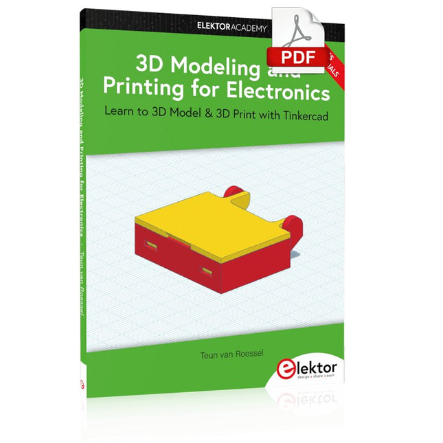
Elektor Digital 3D Modeling and Printing for Electronics (E-book)
Learn to 3D Model & 3D Print with Tinkercad With this book and the complementary videos, you’ll be 3D printing in no time at all. This course is meant to have you make casings for electronic components but also goes into optimizing your print technique as well as adding a little flair to your 3D creations. The course is perfect for you if you just bought your (first) 3D printer and want to print your own designs as soon as possible while also being able to get more background information. You’ll get to know the workings of a 3D printer and what software to use to model your object, not forgetting to make it print perfectly. We’ll even use the magic of 3D printing to create things that appear impossible to make (this fast and simple) with any other rapid-prototyping technique. At the end of this course, it’ll be second nature for you to design an object for 3D printing and fine-tune your print-setting to get the perfect print! The book includes the following 7 video tutorials: Introduction Basic 3D modeling for 3D printing Modeling a casing Post-processing Pushing the limits Movable parts Snap fits
€ 32,95
Mitglieder: € 29,66
-

Elektor Digital Elektor November/December 2024 (PDF)
Elektor GREEN and GOLD members can download their digital edition here. Not a member yet? Click here. Audio DSP FX Processor BoardPart 1: Features and Design 50 Years of Elektor in English KiCad 8Top New and Updated Features Elektor MultiCalculator KitAn Arduino-Based Calculator Kit for Electronic Purposes Low-Cost GNSS RTK SystemsWith Centimeter-Level Degree of Accuracy PCB Layout and SafetyHints for a Safe, Long-Life Design of Your Boards Opamp TesterFor Audio and Other Applications Project Update #4: ESP32-Based Energy MeterEnergy Monitoring with MQTT Real-Time Spectrum Analyzer with Waveguide Technology and Multi-Interface PCsAaronia Establishes New Product Segment and Presents First Prototypes at Electronica in Munich Applications of Ynvisible’s E-paper DisplaysTransform Businesses and Shape the Future SMT InductorsCoils and Ferrites — Selection Made Easy Arrow Electronics to Showcase Innovative Technologies at electronica 2024 Using EMI Shielding to Achieve Electromagnetic Compatibility Compliance The Ultimate Tool for Every Electronics EnthusiastUnlock Endless Possibilities with Red Pitaya and 1,000+ Click Boards™ V-LD1 Distance Radar Module Siglent Presents Its New Vector Network Analyzer Platform SNA6000A HDI in the MiddleA New Cost-Effective PCB Pooling Service for Tiny BGAs Remote Access IoT LabOne and Only Solution for Remote Learning and Development in Embedded Industry Challenges of DFM Analysis for Flex and Rigid-Flex Design From Life's ExperienceMicrotechnophobia 3D Christmas TreeA 3D PCB with a Low-Cost, 32-bit Microcontroller Starting Out in Electronics……Continues with the Opamp! An Autonomous Sensor Node (Project Update #1)Reducing Idle Power Consumption with External RTC and Power Switch 2024: An AI OdysseyA Look Back at the Future LED Displays with the MAX7219A Hands-On Approach to a Great Chip Err-lectronicsCorrections, Updates, and Readers’ Letters VibroTactile GlovesA Breakthrough for Parkinson’s Patients
€ 7,50
-

Elektor Digital Universal Display Book for PIC Microcontrollers (E-book)
The newcomer to Microchip’s PIC microcontrollers invariably gets an LED to flash as their first attempt to master this technology. You can use just a simple LED indicator in order to show that your initial attempt is working, which will give you confidence to move forward. This is how the book begins — simple programs to flash LEDs, and eventually by stages to use other display indicators such as the 7-segment display, alphanumeric liquid crystal displays and eventually a colour graphic LCD. As the reader progresses through the book, bigger and upgraded PIC chips are introduced, with full circuit diagrams and source code, both in assembler and C. In addition, a small tutorial is included using the MPLAB programming environment, together with the EAGLE schematic and PCB design package to enable readers to create their own designs using the book’s many case studies as working examples to work from.
€ 19,95
Mitglieder: € 17,96


