Der Elektor Zenerdioden-Tester ist im Wesentlichen eine Konstantstromquelle, die in Stufen von 1 bis 50 mA geschaltet werden kann. Er kann verwendet werden, um Z-Dioden bis zu maximal 54 V zu testen. Dank eines 60-V-Step-up-Wandlers kann das Gerät mit den üblichen 5 bis 12 V versorgt werden.
Das Prinzip dieses Testers ist einfach. Eine Z-Diode oder ein anderes DUT (device under test, also ein Prüfling, wie z. B. eine LED) wird über eine einstellbare Stromquelle vorgespannt. Die Spannung über dem DUT kann mit einem Multimeter gemessen werden. Die Spannung der meisten (kleinen) Z-Dioden ist bei einem Strom von 5 mA spezifiziert. Je nach Anwendung kann auch die Spannung bei anderen Strömen interessant sein. Deshalb stehen sechs Stromeinstellungen zur Verfügung: 1, 2, 5, 10, 20 und 50 mA. LEDs sind häufig bei einem Strom von 20 mA spezifiziert.
Getestet werden kann:
Ob eine Z-Diode defekt ist (Kurzschluss oder hochohmig).
Ob eine Z-Diode die korrekte Z-Spannung aufweist.
Wie sich eine Z-Spannung bei unterschiedlichen Strömen verändert.
Welche exakte Spannung an einer integrierten Spannungsreferenz anliegt.
Ob sich LEDs in einer Reihenschaltung in ihrer Helligkeit unterscheiden (daher der Strom von 20 mA).
Wie hoch die Stromverstärkung bei unterschiedlichen Basisströmen in (Leistungs-)Transistoren ist.
Das Kit enthält alle in der Stückliste aufgeführten Teile, einschließlich Platine und Gehäuse.
Technische Daten
Versorgungsspannung
5…12 V/2 A (USB-C)
Versorgungsstrom (Itest = 50 mA)
1,1 A bei 5 V / 412 mA bei 12 V
Wählbare Ströme
1, 2, 5, 10, 20 und 50 mA
Max. Prüfspannung
>54 V bei Itest ≥1 mA
Max. Ausgangsspannung
60 V bei Itest = 0 mA
Spannungsbegrenzung bei 5 V
4,5 V bei Itest = 1 mA / 5,18 V bei Itest = 50 mA
Gehäuseabmessungen
110 x 82 x 44 mm
Platinengröße
105,4 x 67,3 mm
Anschlüsse
4-mm-Bananenbuchsen für Multimeter
2-mm-Bananenbuchsen für Prüfklemmen
USB-C-Buchse für die Spannungsversorgung
Lieferumfang
Widerstände
R1 = 3.3 kΩ, 600 mW, 1%
R2 = 0.15 Ω, 1 W, 5%, LS 12.7 mm, ø 3.5 mm
R3, R8 = 180 Ω, 600 mW, 1%
R4, R6, R16 = 1 kΩ, 600 mW, 1%
R5, R19 = 47 kΩ, 600 mW, 1%
R7 = 3.9 kΩ, 1 W, 5%, LS 12.7 mm, ø 3.5 mm
R9, R10, R12 = 10 kΩ, 600 mW, 1%
R11, R13 = 100 Ω, 600 mW 1%
R14 = 249 Ω, 600 mW, 1%
R15 = 499 Ω, 600 mW, 1%
R17 = 2.49 kΩ, 250 mW, 1%
R18 = 4.99 kΩ, 250 mW, 1%
Kondensatoren
C1 = 470 uF / 35 V, 20%, Ir = 1.86 A, ø 12.5 mm, LS 5 mm, ESR = 0.038 Ω (Panasonic EEUTP1V471)
C2 = 1 uF / 100 V, 10%, X7R, LS 5 mm
C3 = 2.2 nF / 50 V, 10%, X7R, LS 5 mm
C4, C7 = 100 nF / 100 V, 10%, X7R, LS 5 mm
C5 = 100 uF / 100 V, 20%, ø 14 mm max., LS 5 mm
C6 = 1 nF / 100 V, 10%, X7R, LS 5 mm
Induktor
L1 = 100 uH, Irms = 2.4 A, Isat = 3.5 A, 0.09 Ω, radial, pitch 2.5/5/10 mm, ø 14 mm max. (Kemet SBC8-101-242)
Halbleiter
D1 = MUR120G, DO-41
D2, D4 = STPS3150RL, DO-201AD
D3 = Z-diode, 18 V, 1.3 W (BZX85C18)
D5 = Z-diode, 5.1 V, 0.5 W (1N5231B)
LED1 = LED in pushbutton S1
LED2 = LED, green, 3 mm
IC1 = MC34063, DIP-8
IC2 = LM4040BIZ-5.0/NOPB, TO-92 (TO-226AA-3)
IC3 = TL051CP, DIP-8
T1 = BC327.25, TO-92
T2 = STP40NF10L, TO-220
T3 = IRF9510PBF, TO-220
T4 = 2N7000, TO-92
Sonstiges
K1, K2, S1, S3 = 2-way screw terminal block, LS 3.5 mm, max. 1.5 mm²
connected to K1 = USB-C socket, 30 V/3 A, chassis mounted, wired, 9 x 16 mm
connected to K2 = Banana Connector, 2 mm, Socket, 60 VDC, Panel Mount, red (Multicomp 24.102.1)
connected to K2 = Banana Connector, 2 mm, Socket, 60 VDC, Panel Mount, black (Multicomp 24.102.2)
Test clip, red, 30 VAC/60 VDC (Hirschmann 931467101)
Test clip, black, 30 VAC/60 VDC (Hirschmann 931467100)
S1 = Pushbutton, panel mount, SPST-NO, 30 DC/100 mA, with red LED
S2 = Rotary Switch, 6 position, 2 pole, 30°, 250 V/150 mA
S3 = Toggle switch, panel mount, SPDT, solder lugs, 28 VDC
T2, T3 = Heat sink, 15°C/W, FK 214 SA-CB
Enclosure Hammond 1591XXSSBK, ABS, 110 x 82 x 44 mm
Knob for S2, round shaft 6 mm, ø 21 mm, with indicator line (Multicomp CP-LB21-6-6D)
4 x Self-tapping screw #4-1/4", carbon steel, pan head
Banana plug, red, 2 mm, 60 VDC (Multicomp 25.205.1)
Banana plug, black, 2 mm, 60 VDC (Multicomp 25.205.2)
Banana socket, black 4 mm, panel mount
Banana socket, red 4 mm, panel mount
for LED1, LED2 = Pin header, 1 x 2, vertical, pitch 2.54 mm
for LED1, LED2 = Pin socket, 1 x 2, vertical, pitch 2.54 mm
for T2, T3 = M3 screw, 10 mm, steel, pan head
2 x M3 washer, plain, steel
4 x M3 nut
for IC1, IC3 = DIP-8 socket
Wire, black, 0.25 mm² (24 AWG), stranded 14 x 0.15 mm, 1 m
Wire, red, 0.25 mm² (24 AWG), stranded 14 x 0.15 mm, 1 m
PCB 250772-1 v1.1
Links
Artikel
Elektor Labs
Das Siglent SDS1104X-E verwendet eine neue Generation der SPO (Super Phosphor Oscilloscope) Technologie, die eine exzellente Signalgenauigkeit und -leistung bietet. Das Systemrauschen ist auch niedriger als bei ähnlichen Produkten in der Branche. Es kommt mit einem minimalen vertikalen Eingangsbereich von 500 uV/div, einem innovativen digitalen Trigger-System mit hoher Empfindlichkeit und geringem Jitter sowie einer Wellenform-Aufnahme-Rate von 400.000 Bildern/sek (Sequenzmodus).
Das SDS1104X-E verfügt auch über eine 256-Stufen-Intensitätsgradierungsfunktion und einen Farbtemperatur-Anzeigemodus, die in anderen Modellen dieser Klasse nicht zu finden sind. Die neuesten Oszilloskope von SIGLENT unterstützen mehrere leistungsstarke Trigger-Modi, einschließlich Serial Bus Triggering. Die serielle Dekodierung ist kostenlos und umfasst IIC, SPI, UART, CAN und LIN. Die Aufzeichnung von Verlaufs-Wellenformen und sequentielles Triggern ermöglichen eine erweiterte Wellenform-Aufzeichnung und -Analyse. Eine weitere leistungsstarke Ergänzung ist die neue 1-Mpt-FFT-Mathematikfunktion, die dem SDS1104X-E eine sehr hohe Frequenzauflösung beim Beobachten von Signal-Spektren gibt.
Features
Intelligenter Trigger: Edge, Slope, Pulse Width, Window, Runt, Interval, Timeout (Dropout) und Pattern
Kostenloses Serial Bus Triggering und Dekodierung: IIC, SPI, UART, RS232, CAN und LIN
Video-Trigger und Unterstützung für HDTV
Niedriges Hintergrundrauschen und Spannungsbereiche von 500 μV/div bis 10 V/div
10 Arten von Ein-Knopf-Verknüpfungen, unterstützt Auto Setup, Default, Cursors, Measure, Roll, History, Display/Persist, Clear Sweep, Zoom und Print
Segmentierte Erfassung (Sequenz) Modus, der die maximale Aufzeichnungslänge in mehrere Segmente (bis zu 80.000) unterteilt, je nach vom Benutzer festgelegten Triggerbedingungen, mit einem sehr kleinen Segment mit geringer Verzögerungszeit, um das qualifizierende Ereignis zu erfassen.
Verlaufs-Wellenaufzeichnung (History) Funktion, die maximale aufgezeichnete Wellenformlänge beträgt 80.000 Bilder
Automatische Messfunktion für 38 Parameter, unterstützt Statistik-, Gate-Messung, Math-Messung, History-Messung und Ref-Messung
1 Mpt FFT
Echte Messung und Mathematik können alle 14 Mpts des Speichers nutzen
Voreinstellungstasten können für Benutzereinstellungen oder werkseitige 'Standardeinstellungen' angepasst werden
Sicherheits-Löschmodus
Highspeed-Hardware-basierte Pass/Fail-Funktion
Großer 7-Zoll-TFT-LCD-Bildschirm mit 800 * 480 Auflösung
Mehrere Schnittstellentypen: USB-Host, USB-Gerät (USB-TMC), LAN (VXI-11), Pass/Fail, Trigger Out
Unterstützt SCPI-Fernsteuerbefehle
Mehrsprachige Anzeige und eingebettete Hilfe
Browser-Steuerung/Onboard-Webseite zur softwarefreien Überwachung (nur 4-Kanal-Modelle)
Lieferumfang
1x Siglent SDS1104X-E Oszilloskop
4x 100 MHz Sonden
1x Garantiekarte
1x Netzkabel
1x USB-Kabel
1x Schnellstartanleitung
Downloads
Datasheet
Manual
Programming Guide
Der Siglent SSA3032X Plus Spektrum-Analyzer ist ein leistungsstarkes und flexibles Werkzeug für die HF-Signal- und Netzwerkanalyse. Mit einem Frequenzbereich von 3,2 GHz bietet der Analysator zuverlässige automatische Messungen und mehrere Betriebsarten: Spektrum-Analyzer als Basis, optionale Funktionen umfassen HF-Leistungsmessung, Vektorsignal-Modulationsanalyse, Reflexionsmessung und EMI-Test.
Zu den Anwendungsbereichen gehören die Überwachung/Bewertung von Sendungen, Standortvermessung, S-Parameter-Messung, analoge/digitale Modulationsanalyse, EMI-Vorprüfung, Forschung und Entwicklung, Ausbildung, Produktion und Wartung.
Features
Frequenzbereich des Spektrum-Analyzer von 9 kHz bis 3,2 GHz
–161 dBm/Hz Angezeigter durchschnittlicher Geräuschpegel (typisch)
–98 dBc/Hz. @ 10 kHz Offset-Phasenrauschen (1 GHz, typ.)
Pegelmessunsicherheit <0,7 dB (typ.)
1 Hz Mindestauflösungsbandbreite (RBW)
Vorverstärker (Std.)
Tracking Generator (kostenlos inkl.)
Analysemodus für analoge und digitale Signalmodulation (opt.)
Reflexionsmesskit (opt.)
EMI-Filter und Quasi-Peak-Detektor-Kit (opt.)
Erweitertes Messkit (opt.)
10,1-Zoll-Multi-Touch-Bildschirm, Maus und Tastatur werden unterstützt
Webbrowser-Fernsteuerung auf PCs und mobilen Endgeräten sowie Dateibetrieb
Technische Daten
SSA3015X Plus
SSA3021X Plus
SSA3032X Plus
SSA3075X Plus
Frequenzbereich
9 kHz ~ 1,5 GHz
9 kHz ~ 2,1 GHz
9 kHz ~ 3,2 GHz
9 kHz ~ 7,5 GHz
Auflösung Bandbreite
1 Hz ~ 1 MHz
1 Hz ~ 1 MHz
1 Hz ~ 1 MHz
1 Hz ~ 3 MHz
Phasenrauschen
<–99 dBc/Hz
<–98 dBc/Hz
<–98 dBc/Hz
<–98 dBc/Hz
Genauigkeit der Gesamtamplitude
<1,2 dB
<0,7 dB
<0,7 dB
<0,7 dB
Anzeige des durchschnittlichen Geräuschpegels
–156 dBm/Hz
–161 dBm/Hz
–161 dBm/Hz
–165 dBm/Hz
Lieferumfang
Siglent SSA3032X Plus Spektrum-Analyzer
USB-Kabel
Netzkabel
Kurzanleitung
Downloads
Datasheet
Manual
Documentation
Firmware
Der Siglent SSA3021X Plus Spektrum-Analyzer ist ein leistungsstarkes und flexibles Werkzeug für die HF-Signal- und Netzwerkanalyse. Mit einem Frequenzbereich von 2,1 GHz bietet der Analysator zuverlässige automatische Messungen und mehrere Betriebsarten: Spektrum-Analyzer als Basis, optionale Funktionen umfassen HF-Leistungsmessung, Vektorsignal-Modulationsanalyse, Reflexionsmessung und EMI-Test.
Zu den Anwendungsbereichen gehören die Überwachung/Bewertung von Sendungen, Standortvermessung, S-Parameter-Messung, analoge/digitale Modulationsanalyse, EMI-Vorprüfung, Forschung und Entwicklung, Ausbildung, Produktion und Wartung.
Features
Frequenzbereich des Spektrum-Analyzer von 9 kHz bis 2,1 GHz
–161 dBm/Hz Angezeigter durchschnittlicher Geräuschpegel (typisch)
–98 dBc/Hz. @ 10 kHz Offset-Phasenrauschen (1 GHz, typ.)
Pegelmessunsicherheit <0,7 dB (typ.)
1 Hz Mindestauflösungsbandbreite (RBW)
Vorverstärker (Std.)
Tracking Generator (kostenlos inkl.)
Analysemodus für analoge und digitale Signalmodulation (opt.)
Reflexionsmesskit (opt.)
EMI-Filter und Quasi-Peak-Detektor-Kit (opt.)
Erweitertes Messkit (opt.)
10,1-Zoll-Multi-Touch-Bildschirm, Maus und Tastatur werden unterstützt
Webbrowser-Fernsteuerung auf PCs und mobilen Endgeräten sowie Dateibetrieb
Technische Daten
SSA3015X Plus
SSA3021X Plus
SSA3032X Plus
SSA3075X Plus
Frequenzbereich
9 kHz ~ 1,5 GHz
9 kHz ~ 2,1 GHz
9 kHz ~ 3,2 GHz
9 kHz ~ 7,5 GHz
Auflösung Bandbreite
1 Hz ~ 1 MHz
1 Hz ~ 1 MHz
1 Hz ~ 1 MHz
1 Hz ~ 3 MHz
Phasenrauschen
<–99 dBc/Hz
<–98 dBc/Hz
<–98 dBc/Hz
<–98 dBc/Hz
Genauigkeit der Gesamtamplitude
<1,2 dB
<0,7 dB
<0,7 dB
<0,7 dB
Anzeige des durchschnittlichen Geräuschpegels
–156 dBm/Hz
–161 dBm/Hz
–161 dBm/Hz
–165 dBm/Hz
Lieferumfang
Siglent SSA3021X Plus Spektrumanalysator
USB-Kabel
Netzkabel
Kurzanleitung
Downloads
Datasheet
Manual
Documentation
Firmware
Realize your own projects with the Elektor Arduino Nano MCCAB Training Board
The microcontroller is probably the most fascinating subfield of electronics. Due to the multitude of functions, it combines on its chip, it is a universal multi-tool for developers to realize their projects. Practically every device of daily use today is controlled by a microcontroller. However, for an electronic layman, realizing his own ideas with a microcontroller has so far remained a pipe dream due to its complexity. The Arduino concept has largely simplified the use of microcontrollers, so that now even laymen can realize their own electronics ideas with a microcontroller.
Book & Hardware in the Bundle: 'Learning by Doing'
This book, which is included in the bundle, shows how you can realize your own projects with a microcontroller even without much experience in electronics and programming languages. It is a microcontrollers hands-on course for starters, because after an overview of the internals of the microcontroller and an introduction to the programming language C, the focus of the course is on the practical exercises. The reader acquires the necessary knowledge by 'learning by doing': in the extensive practical section with 12 projects and 46 exercises, what is learned in the front part of the book is underpinned with many examples. The exercises are structured in such a way that the user is given a task to solve using the knowledge built up in the theoretical part of the book. Each exercise is followed by a sample solution that is explained and commented on in detail, which helps the user to solve problems and compare it with his own solution.
Arduino IDE
The Arduino IDE is a software development environment that can be downloaded for free to your own PC and that contains the entire software package needed for your own microcontroller projects. You write your programs ('apps') with the IDE’s editor in the C programming language. You translate them into the bits and bytes that the microcontroller understands using the Arduino IDE's built-in compiler, and then load them into the microcontroller's memory on the Elektor Arduino MCCAB Nano Training Board via a USB cable.
Query or control external sensors, motors or assemblies
In addition to an Arduino Nano microcontroller module, the Elektor Arduino Nano MCCAB Training Board contains all the components required for the exercises, such as light-emitting diodes, switches, pushbuttons, acoustic signal transmitters, etc. External sensors, motors or assemblies can also be queried or controlled with this microcontroller training system.
Specifications (Arduino Nano MCCAB Training Board)
Power Supply
Via the USB connection of the connected PC or an external power supply unit (not included)
Operating Voltage
+5 Vcc
Input Voltage
All inputs
0 V to +5 V
VX1 and VX2
+8 V to +12 V (only when using an external power supply)
Hardware periphery
LCD
2x16 characters
Potentiometer P1 & P2
JP3: selection of operating voltage of P1 & P2
Distributor
SV4: Distributor for the operating voltagesSV5, SV6: Distributor for the inputs/outputs of the microcontroller
Switches and buttons
RESET button on the Arduino Nano module 6x pushbutton switches K1 ... K6 6x slide switches S1 ... S6 JP2: Connection of the switches with the inputs of the microcontroller
Buzzer
Piezo buzzer Buzzer1 with jumper on JP6
Indicator lights
11 x LED: Status indicator for the inputs/outputs LED L on the Arduino Nano module, connected to GPIO D13 JP6: Connection of LEDs LD10 ... LD20 with GPIOs D2 ... D12
Serial interfacesSPI & I²C
JP4: Selection of the signal at pin X of the SPI connector SV12 SV9 to SV12: SPI interface (3.3 V/5 V) or I²C interface
Switching output for external devices
SV1, SV7: Switching output (maximum +24 V/160 mA, externally supplied) SV2: 2x13 pins for connection of external modules
3x3 LED matrix(9 red LEDs)
SV3: Columns of the 3x3 LED matrix (outputs D6 ... D8) JP1: Connection of the rows with the GPIOs D3 ... D5
Software
Library MCCABLib
Control of hardware components (switches, buttons, LEDs, 3x3 LED matrix, buzzer) on the MCCAB Training Board
Operating Temperature
Up to +40 °C
Dimensions
100 x 100 x 20 mm
Specifications (Arduino Nano)
Microcontroller
ATmega328P
Architecture
AVR
Operating Voltage
5 V
Flash Memory
32 KB, of which 2 KB used by bootloader
SRAM
2 KB
Clock Speed
16 MHz
Analog IN Pins
8
EEPROM
1 KB
DC Current per I/O Pins
40 mA on one I/O pin, total maximum 200 mA on all pins together
Input Voltage
7-12 V
Digital I/O Pins
22 (6 of which are PWM)
PWM Output
6
Power Consumption
19 mA
Dimensions
18 x 45 mm
Weight
7 g
Included
Elektor Arduino Nano MCCAB Training Board
Arduino Nano
Book: Microcontrollers Hands-on Course for Arduino Starters
The Siglent SPD4306X is a 4-channel DC Linear Programmable Power Supply equipped with a 4.3-inch TFT-LCD display, friendly human-machine interface, and excellent performance indicators. Real-time waveform display provides engineers with an informative user interface.
SPD4306X offers a total output power of 400 W with a resolution of 1 mV/1 mA. The maximum voltage and current for each channel are as follows:
CH1: 15 V/1.5 A
CH2: 30 V/6 A
CH3: 30 V/6 A
CH4: 15 V/1 A
Features
Rated output power: 400 W
Rated voltage: 32 V, 12 V, 30 V
Up to four high-precision power supplies with independent controllable outputs, supporting CH2 and CH3 series and parallel connections
Clear graphical interface with waveform and timer display modes
5-digit voltage and current display with minimum resolution of 1 mV, 1 mA
Fast output response time: <50us
The high current channel support remote voltage compensation sense function. The maximum compensation voltage is 0.6 V
Overvoltage protection and overcurrent protection or safe and accurate operation
Equipped with a 4.3-inch TFT-LCD display (480 x 272 resolution)
USB and LAN standard communication
USB-GPIB module is optional
Excellent channel density with up to 4 channels in a 3U half rack package
Internal data storage for setups and parameters
Embedded Web Server with instrument communication that doesn’t require software installation
Fully SCPI programming command set support as well as a LabView driver for remote control and system automation
Technische Daten
SPD4323X
SPD4121X
SPD4306X
Channel Output
CH1: Voltage 0 to 6 V Current 0 to 3.2 ACH2: Voltage 0 to 32 V Current 0 to 3.2 ACH3: Voltage 0 to 32 V Current 0 to 3.2 ACH4: Voltage 0 to 6 V Current 0 to 3.2 A
CH1: Voltage 0 to 15 V Current 0 to 1.5 ACH2: Voltage 0 to 12 V Current 0 to 10 ACH3: Voltage 0 to 12 V Current 0 to 10 ACH4: Voltage 0 to 15 V Current 0 to 1.5 A
CH1: Voltage 0 to 15 V Current 0 to 1.5 ACH2: Voltage 0 to 30 V Current 0 to 6 ACH3: Voltage 0 to 30 V Current 0 to 6 ACH4: Voltage 0 to 15 V Current 0 to 1 A
Resolution
1 mV, 1 mA
1 mV, 1 mA
1 mV, 1 mA
Setting Accuracy
Voltage: ±(0.03% of reading+10) mV, Current: ±(0.3% of reading+10) mA
Voltage: ±(0.03% of reading+10) mV, Current: ±(0.3% of reading+10) mA
Voltage: ±(0.03% of reading+10) mV, Current: ±(0.3% of reading+10) mA
Readback Accuracy
Voltage: ±(0.03% of reading+10) mV, Current: ±(0.3% of reading+10) mA
Voltage: ±(0.03% of reading+10) mV, Current: ±(0.3% of reading+10) mA
Voltage: ±(0.03% of reading+10) mV, Current: ±(0.3% of reading+10) mA
Display
4.3" TFT-LCD 5-digit voltage and current display
4.3" TFT-LCD 5-digit voltage and current display
4.3" TFT-LCD 5-digit voltage and current display
Output power
240 W
285 W
400 W
Lieferumfang
1x Siglent SPD4306X Power Supply
1x Power cord (EU)
1x Output test cord (3 A)
1x USB cable
1x Quick start guide
Downloads
Datasheet
Manual
Quick start
Das Siglent SDS1204X-E ist ein leistungsstarkes 200-MHz-Vierkanal-Oszilloskop, das auf der gleichen Plattform wie das sehr beliebte SDS1202X-E basiert, jedoch mehrere wesentliche Verbesserungen aufweist, darunter zwei 1-GSa/s-ADCs und zwei 14-Mpt-Speichermodule. Die Wellenform-Erfassungsraten betragen bis zu 100.000 Wfms/s im Normalmodus und 400.000 Wfms/s im Sequenzmodus. Die SDS1000X-E-Zielfernrohre verfügen über ein großes 7-Zoll-Farbdisplay mit 256 Stufen und Funktionen zur Intensitätsabstufung und Farbtemperatur.
Technische Daten
Bandbreite
200 MHz
Abtastrate (max.)
1 GSa/s
Kanäle
2CH+EXT 4CH
Speichertiefe (max.)
7 Mpts/CH (kein Interleave-Modus); 14 Mpts/CH (Interleave-Modus)
Wellenform-Erfassungsrate (max.)
100.000 Wfms/s (Normalmodus), 400.000 Wfms/s (Sequenzmodus)
Triggertypen
Flanke, Steigung, Impulsbreite, Fenster, Runt, Intervall, Dropout, Muster, Video
Serieller Trigger (Standard)
I 2 C, SPI, UART/RS232, CAN, LIN
Dekodierungstyp (Standard)
I 2 C, SPI, UART/RS232, CAN, LIN
16 digitale Kanäle (nur Vierkanalserie, Option)
Maximale Wellenform-Erfassungsrate bis zu 1 GSa/s, Aufzeichnungslänge bis zu 14 Mpts/CH
USB-AWG-Modul (nur Vierkanalserie, Option)
Ein Kanal, 25 MHz, Abtastrate 125 MHz, Wellenlänge 16 kpts
Bode-Diagramm (nur Vierkanalserie)
Mindeststartfrequenz 10 Hz, Mindestscanbandbreite 500 Hz, maximale Scan-Bandbreite von 120 MHz (abhängig von Oszilloskop und AWG-Bandbreite), 500 maximale Scanfrequenzpunkte
USB-WLAN-Adapter (nur Vierkanalserie, Option)
802.11b/g/b, WPA-PSK, der Adapter muss von Siglent geliefert werden, um eine ordnungsgemäße Funktion zu gewährleisten
Downloads
Datasheet
Manual
Programming Guide
Dieser USB Logic Analyzer ist ein 8-Kanal-Logikanalysator, bei dem jeder Eingang doppelt für die analoge Datenaufzeichnung dient. Es eignet sich perfekt zum Debuggen und Analysieren von Signalen wie I²C, UART, SPI, CAN und 1-Wire. Dabei wird ein digitaler Eingang, der mit einem zu testenden Gerät (DUT) verbunden ist, mit einer hohen Abtastrate abgetastet. Die Verbindung zum PC erfolgt via USB.Technische DatenKanäle8 digitale KanäleMaximale Abtastrate24 MHzMaximale Eingangsspannung0 V ~ 5 VBetriebstemperatur0°C ~ 70°CEingangsimpedanz1 MΩ || 10 pFUnterstützte ProtokolleI²C, SPI, UART, CAN, 1-Wire etc.PC-VerbindungUSBAbmessungen55 x 28 x 14 mmLieferumfangUSB Logic Analyzer (8 Kanäle, 24 MHz)USB-KabelJumper Wire Ribbon KabelDownloadsSoftware
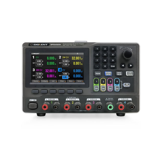
The Siglent SPD4323X is a 4-channel DC Linear Programmable Power Supply equipped with a 4.3-inch TFT-LCD display, friendly human-machine interface, and excellent performance indicators. Real-time waveform display provides engineers with an informative user interface.
SPD4323X offers a total output power of 240 W with a resolution of 1 mV/1 mA. The maximum voltage and current for each channel are as follows:
CH1: 6 V/3.2 A
CH2: 32 V/3.2 A
CH3: 32 V/3.2 A
CH4: 6 V/3.2 A
Features
Rated output power: 240 W
Rated voltage: 32 V, 12 V, 30 V
Up to four high-precision power supplies with independent controllable outputs, supporting CH2 and CH3 series and parallel connections
Clear graphical interface with waveform and timer display modes
5-digit voltage and current display with minimum resolution of 1 mV, 1 mA
Fast output response time: <50us
The high current channel support remote voltage compensation sense function. The maximum compensation voltage is 0.6 V
Overvoltage protection and overcurrent protection or safe and accurate operation
Equipped with a 4.3-inch TFT-LCD display (480 x 272 resolution)
USB and LAN standard communication
USB-GPIB module is optional
Excellent channel density with up to 4 channels in a 3U half rack package
Internal data storage for setups and parameters
Embedded Web Server with instrument communication that doesn’t require software installation
Fully SCPI programming command set support as well as a LabView driver for remote control and system automation
Technische Daten
SPD4323X
SPD4121X
SPD4306X
Channel Output
CH1: Voltage 0 to 6 V Current 0 to 3.2 ACH2: Voltage 0 to 32 V Current 0 to 3.2 ACH3: Voltage 0 to 32 V Current 0 to 3.2 ACH4: Voltage 0 to 6 V Current 0 to 3.2 A
CH1: Voltage 0 to 15 V Current 0 to 1.5 ACH2: Voltage 0 to 12 V Current 0 to 10 ACH3: Voltage 0 to 12 V Current 0 to 10 ACH4: Voltage 0 to 15 V Current 0 to 1.5 A
CH1: Voltage 0 to 15 V Current 0 to 1.5 ACH2: Voltage 0 to 30 V Current 0 to 6 ACH3: Voltage 0 to 30 V Current 0 to 6 ACH4: Voltage 0 to 15 V Current 0 to 1 A
Resolution
1 mV, 1 mA
1 mV, 1 mA
1 mV, 1 mA
Setting Accuracy
Voltage: ±(0.03% of reading+10) mV, Current: ±(0.3% of reading+10) mA
Voltage: ±(0.03% of reading+10) mV, Current: ±(0.3% of reading+10) mA
Voltage: ±(0.03% of reading+10) mV, Current: ±(0.3% of reading+10) mA
Readback Accuracy
Voltage: ±(0.03% of reading+10) mV, Current: ±(0.3% of reading+10) mA
Voltage: ±(0.03% of reading+10) mV, Current: ±(0.3% of reading+10) mA
Voltage: ±(0.03% of reading+10) mV, Current: ±(0.3% of reading+10) mA
Display
4.3" TFT-LCD 5-digit voltage and current display
4.3" TFT-LCD 5-digit voltage and current display
4.3" TFT-LCD 5-digit voltage and current display
Output power
240 W
285 W
400 W
Lieferumfang
1x Siglent SPD4323X Power Supply
1x Power cord (EU)
1x Output test cord (3 A)
1x USB cable
1x Quick start guide
Downloads
Datasheet
Manual
Quick start
Dieses Bundle enthält alles, was Sie brauchen, um direkt mit dem XIAO ESP32-C3 Development Board loszulegen. Lernen Sie die Grundlagen des ESP32-C3 kennen und entwickeln Sie praktische Projekte mit Wi-Fi, Bluetooth, Sensoren, Displays, PWM, Deep Sleep und vielem mehr.
Buch: Build Smart Projects with the XIAO ESP32-C3 Board
Das XIAO ESP32-C3 Board kombiniert den ultrakompakten Formfaktor der XIAO-Serie mit den umfangreichen Funktionen des ESP32-C3-Chips, einschließlich integriertem Wi-Fi und Bluetooth 5.0. Dieses Buch ist ein umfassender, praxisorientierter Leitfaden, mit dem Sie das Potenzial dieses leistungsstarken und dennoch preisgünstigen Development Boards voll ausschöpfen können.
Der Autor führt die Leser von den Grundlagen bis hin zu fortgeschrittenen Projekten. Angefangen beim Blinken und Dimmen von LEDs geht es weiter mit ADC und PWM für die präzise Anbindung von Sensoren und PWM-gesteuerte Lichteffekte, bevor praktische Anwendungen aus der realen Welt umgesetzt werden, darunter:
Eine Wi-Fi-Wetterstation mit OLED-Display und aktuellen Online-Wetterdaten
Ein Ultraschall-Einparkassistent mit akustischer Rückmeldung
Eine Kühlschrank-Messsonde mit Klimasensoren und Deep Sleep für jahrelangen Batteriebetrieb
Ein Retro-Pong-Spiel, das berührungslos per Sensor gesteuert wird
Eine mikrofonbasierte Party-App, die auf Klatschen reagiert
Und vieles mehr: Lichtsteuerung, Reaktionszeitmessung, Netzfrequenzanalyse, Bodenfeuchtemessung, LED-Ambientebeleuchtung und 7-Segment-Anzeigen
Seeed Studio XIAO ESP32C3
Das Seeed Studio XIAO ESP32C3 ist mit einem hochintegrierten ESP32-C3-Chip ausgestattet, der auf einem 32-Bit-RISC-V-Prozessor mit vierstufiger Pipeline basiert und mit bis zu 160 MHz arbeitet.
Das Board verfügt über ein hochintegriertes ESP32-C3-SoC. Der Chip ist mit einem vollständigen 2,4-GHz-Wi-Fi-Subsystem ausgestattet und unterstützt damit den Station-Modus, SoftAP-Modus, SoftAP-&-Station-Modus sowie den Promiscuous-Modus für unterschiedliche Wi-Fi-Anwendungen. Gleichzeitig arbeitet er äußerst energieeffizient und unterstützt Bluetooth 5 sowie Bluetooth Mesh. Mit 400 KB SRAM und 4 MB Flash bietet der Chip ausreichend Speicherplatz für Programme und eröffnet zahlreiche Möglichkeiten für IoT-Steuerungsanwendungen.
Anwendungen
Internet der Dinge (IoT)
Wearables
Gesundheitsüberwachung
Bildung
Energiesparende Netzwerke
Schnelle Prototypenentwicklung
Technische Daten
Processor
ESP32-C3 SoC
RISC-V single-core 32-bit chip processor with a four-stage pipeline that operates at up to 160 MHz
Wireless
Complete 2.4GHz Wi-Fi subsystem
Bluetooth Low Energy 5.0/ Bluetooth Mesh
On-chip Memory
400 KB SRAM & 4 MB Flash
Interface
1x UART, 1x I²C, 1x SPI, 11x GPIO (PWM), 4x ADC
1x Reset button, 1x Boot button
Power (Typ.)
Max 3.3 V Output Current: 500 mA Test Condition: BAT Pin Input @ 3.8 V Source Capability: 3 A
Charging current: 380 mA(Fast) / 40 mA(Trickle)
Input voltage (VIN): 5 VInput voltage (BAT): 3.7 V
Deep Sleep Power Consumption
Deep Sleep Mode: 44 μA
Wi-Fi Enabled Power Consumption
Active Mode: 75 mA
Modem-sleep Mode: 25 mA
Light-sleep Mode: 4 mA
BLE Enabled Power Consumption
Modem-sleep Mode: 27 mA
Light-sleep Mode: 10 mA
Dimensions
21 x 17.8 mm
Lieferumfang
1x Seeed Studio XIAO ESP32C3
1x Antenne
2x 7-Pin-Header
Downloads
Wiki
Datasheet
Dieses Bundle enthält:
Buch: Build Smart Projects with the XIAO ESP32-C3 Board (Einzelpreis: 35 €)
Board: Seeed Studio XIAO ESP32C3 (Einzelpreis: 10 €)
Hochleistungsfähiges LoRa-Kommunikationsgerät
Das Elecrow ThinkNode M5 ist ein kompaktes, tragbares LoRa-Kommunikationsgerät, das für netzunabhängige Nachrichtenübermittlung, Standortfreigabe und den Außeneinsatz konzipiert wurde. Ausgestattet mit einem ESP32-S3-Prozessor und einem SX1262-LoRa-Chip, wird es mit vorinstallierter Meshtastic-Firmware geliefert und lässt sich bequem per Bluetooth über die offizielle Meshtastic-App konfigurieren.
Das integrierte Multi-GNSS-Modul unterstützt GPS, GLONASS, BeiDou und QZSS für eine zuverlässige Positionsbestimmung und Standortfreigabe. Nachrichten und Geräteinformationen werden auf dem energieeffizienten 1,54-Zoll-E-Paper-Display angezeigt, während der integrierte 1.200-mAh-Akku einen langen mobilen Betrieb ermöglicht.
Dank der integrierten LoRa-Antenne, des kompakten Gehäuses, der Echtzeituhr (RTC) und der Unterstützung für Meshtastic- sowie MeshCore-Firmware ist das ThinkNode M5 eine praktische Kommunikationslösung für Wandern, Camping, abgelegene Gebiete und Notfallsituationen, in denen keine herkömmlichen Mobilfunknetze verfügbar sind.
Features
LoRa-Kommunikation
Multi-GNSS-Positionsbestimmung
1.200-mAh-Akku
1,54" E-Paper-Display
Integrierte RTC
Kompatibel mit MeshCore
Kompatibel mit Meshtastic
Technische Daten
Hauptprozessor (ESP32-S3)
CPU/SoC
Xtensa 32-Bit-LX7-Dual-Core-Prozessor, getaktet mit bis zu 240 MHz
Systemspeicher
512 KB SRAM, 8 MB PSRAM
Speicher
4 MB Flash, 384 KB ROM
Firmware
Meshtastic-Firmware ist voll kompatibel; Signalübertragung im LoRa-Modus
EPD (Electronic Paper Display)
Displaygröße
1,54-Zoll-EPD (monochromer E-Ink-Bildschirm)
Displaymaterial
E-Ink (Electronic Ink)
Auflösung
200 x 200
Treiber-Chip
SSD1681 (über SPI- oder I²C-Schnittstelle)
Zeit für vollständige Aktualisierung
2 s
Drahtlose Kommunikation
Bluetooth
Bluetooth Low Energy und Bluetooth 5.0 (Konfiguration per Smartphone)
LoRa
SX1262 LoRa-Modul, EU 868 MHz (externe Antenne)
Hardware
Schnittstellen
USB-C, RP-SMA
Funktionen
GPS-Ortung (GPS, GLONASS, BeiDou, QZSS), EPD-Display, RTC, USB 2.0, PMU-Energiemanagement (integrierter 1200-mAh-Lithium-Akku), Summer usw.
Tasten
Drehschalter, Funktionstaste, Blättertaste, GPS-Schalter, Reset-Taste
LED-Anzeige
Stromversorgung, GPS/LoRa-Anzeige
Sonstiges
Spannungsversorgung
5 V/1 A; unterstützt Stromversorgung über USB oder Lithium-Akku
Stromverbrauch
Maximaler Betriebsstrom ca. 340 mA (CPU + LoRa-Modul); Stromverbrauch im Energiesparmodus ca. 34 µA
Betriebstemperatur
-10 bis 50°C
Lagertemperatur
-20 bis 60°C
Relative Luftfeuchtigkeit
10–95% bei 40°C (nicht kondensierend)
Gehäuse
ABS-Kunststoff
Abmessungen
82 x 51,6 x 26,3 mm
Gewicht
81 g
Lieferumfang
1x Elecrow ThinkNode M5
1x LoRa-Antenne
1x USB-C Kabel
1x Manual
Downloads
Manual