
Suchergebnisse für "mastech OR ms8238h OR digital OR multimeter OR with OR wireless"
-

OWON OWON ADS914A 4-Kanal Oszilloskop (125 MHz)
Die OWON ADS900A-Serie ist ein kompaktes 12-Bit-Digitaloszilloskop mit bis zu 2 GSa/s, 100 MPTS Speicher und 125/250 MHz Bandbreite. Mit seinem 7"-Multitouch-Display, FFT, Protokolldekodierung und integriertem Logikanalysator ermöglicht es eine präzise Signalanalyse für Labor-, Werkstatt- und Feldanwendungen. Technische Daten ADS914A ADS924A Bandwidth (-3 dB) 125 MHz 250 MHz Channels 4 Max. sample rate 2 GSa/s (single-channel) 1 GSa/s (dual-channel) 500 MSa/s (full-channel) DC Gain Accuracy 3% (≤1 mV) 2% (≥2 mV) Max memory depth 100M Vertical resolution 12 bits Relay time accuracy ±25 ppm (typical) Input Impedance 1 MΩ±2%, parallel with20 pF±5 pF Probe Attenuation Coefficient 1.00μX-1M.00X,step by 1-2-5, support custom Trigger type Edge, Video, Pulse, Slope, Runt, Windows, Timeout, Nth, Logic, RS232/UART, I²C, SPI CAN, LIN Bus decoding RS232/UART, I²C, SPI, CAN, LIN Auto measurement Period, Frequency, +Width, -Width, Rise Time, Fall Time, Scr Duty, +Duty,-Duty, Vavg, Vpp, VRMS, Overshoot, Vmax, Vmin, Vtop, CycRms, Vbase, Vamp, Preshoot, Std Dev, +Pulse Cnt, -Pulse Cnt, Rise Cnt, Fall Cnt, Area, Cyc Area, Delay(A↑-B↑), Delay(A↑-B↓), Delay(A↓-B↑), Delay(A↓-B↓), Phase(A↑-B↑) Phase(A↑-B↓), Phase(A↓-B↑), Phase(A↓-B↓), FRR(A↑-B↑), FRF(A↑-B↓) FFR(A↓-B↑), FFF(A↓-B↓), LRR(A↑-B↑), LRF(A↑-B↓), LFR(A↓-B↑), LFF(A↓-B↓) Waveform Math +, -, *, /, &&, ||, ^, !, Intg, Diff, Sqrt, Function operation (Lg / Ln / Exp / Abs / Sine / Cosine / Tan), FFT, FFT rms, User Defined, digital filter (low pass, high pass, band pass, band reject) Frequency counter 6-digit frequency counter Maximum frequency: maximum analog bandwidth of oscilloscope Voltmeter Support DC, AC+DCrms, ACrms, Resolution: 4 digits (ACV/DCV) Logical Analyzer Specifications Number of channels 16 input channels (D0-D15) (D0 to D7, D8 to D15) Max. input voltage ±40V peak CAT I, transient overvoltage 800Vpk Input Impedance 100kΩ, 8 pF Vertical resolution 1 bit Other Communication Interface HDMI, USB device, USB Host, Trig Out (P/F), LAN Display 7 inch (1024x600), capacitive multi-touch screen Power supply interface USB-C Dimensions 260 x 160 x 78 mm Weight 1.5 kg Lieferumfang 1x OWON ADS914A Oszilloskop 1x Netzteil 1x Netzkabel 1x USB-Kabel 1x Sonde 1x Quick Guide Downloads Manual Quick Guide PC Software
€ 570,01
-

Rigol Rigol DSA815-TG Spektrum-Analyzer (9 kHz – 1,5 GHz)
Highlights Frequenz: 1,5 GHz DANL: -155 dBm Phasenrauschen: -80 dBc/Hz RBW: 10 Hz Tracking-Generator Technische Daten Volldigitale ZF-Technologie Frequenzbereich von 9 kHz bis 1,5 GHz Mindest. -161 dBm Angezeigter durchschnittlicher Geräuschpegel (typisch) Mindest. < -98 dBc/Hz bei 10 kHz Offset-Phasenrauschen Pegelmessunsicherheit < 0,8 dB 10 Hz Mindestauflösungsbandbreite Bis zu 1,5 GHz Tracking-Generator Erweiterte Messfunktionen (Opt.) EMI-Filter und Quasi-Peak-Detektor-Kit (Opt.) VSWR-Messkit (Opt.) PC-Software (Opt.) Optionales RF-TX/RX-Trainingskit Optionales HF-Zubehör (Kabel, Adapter, Dämpfungsglied, Brücke...) Vollständige Konnektivität: LAN (LXI), USB-Host und -Gerät, GPIB (Opt.) 8-Zoll-WVGA-Display (800 x 480). Kompakte Größe, leichtes Design Lieferumfang 1x Rigol DSA815-TG Spektrumanalysator 1x Netzkabel 1x USB-Kabel
€ 1.082,95€ 974,66Bestpreis
-

Siglent Siglent SDS814X HD 4-Kanal Oszilloskop (100 MHz)
The Siglent SDS814X HD digital storage oscilloscope is based on 2 GSa/s, 12-bit Analog-Digital Converters and front ends with excellent noise floor performance. With a 100 MHz bandwidth, and a maximum record length of 50 Mpts, and the capability to analyze 4 analog channels alongside 16 digital channels, the SDS814X HD is perfectly suited for mixed signal analysis. Features 12-bit High Resolution 12-bit Analog-Digital Convertors with sample rate up to 2 GSa/s Front ends with 70 μVrms noise floor @ 100 MHz bandwidth 2/4 analog channels, up to 700 MHz bandwidth SPO technology Waveform capture rate up to 80,000 wfm/s (normal mode), and 500,000 wfm/s (sequence mode) Supports 256-level intensity grading and color temperature display modes. Up to 50 Mpts record length Digital trigger system Intelligent trigger: Edge, Slope, Pulse width, Window, Runt, Interval, Dropout, Pattern, Video (HDTV supported), Qualified, Nth edge, Delay, Setup/Hold time. Serial bus triggering and decoder, supports protocols I²C, SPI, UART, CAN, LIN. Segmented acquisition (Sequence) mode, dividing the maximum record length into multiple segments (up to 80,000), according to trigger conditions set by the user, with a very small dead time between segments to capture the qualifying event. History waveform record (History) function, the maximum recorded waveform length is 80,000 frames. Automatic measurements on 50+ parameters, supports statistics with histogram, track, trend, Gating measurement, and measurements on Math, History and Ref. 4 Math traces (2 Mpts FFT, addition, subtraction, multiplication, division, integration, differential, square root, etc.), supports formula editor. Abundant data analysis functions such as Search, Navigate, Counter, Bode plot and Power Analysis High Speed hardware-based Mask Test function, with Mask Editor tool for creating user-defined masks 16 digital channels (optional) 25 MHz waveform generator (optional) 7" TFT-LCD display with 1024 x 600 resolution; Capacitive touch screen supports multi-touch gestures. Interfaces include: USB Hosts, USB Device (USBTMC), LAN (VXI-11/Telnet/Socket), Pass/Fail, Trigger Out Built-in web server supports remote control over the LAN port using a web browser. Supports SCPI remote control commands. Supports external mouse and keyboard. Supports NTP. Technische Daten Analog Channels 4 Bandwidth 100 MHz Vertical resolution 12-bit Sample rate (Max.) One channel mode: 2 GSa/sTwo channel mode: 1 GSa/sFour channel mode: 500 MSa/s Memory depth (Max.) One channel mode: 50 Mpts/chTwo channel mode: 25 Mpts/chFour channel mode: 10Mpts/ch Waveform capture rate (Max.) Normal mode: 80,000 wfm/sSequence mode: 500,000 wfm/s Trigger type Edge, Slope, Pulse width, Window, Runt, Interval, Dropout, Pattern, Video, Qualified, Nth edge, Delay, Setup/Hold time, Serial Serial trigger and decode (Standard) I²C, SPI, UART, CAN, LIN Measurement 50+ parameters, statistics, histogram, trend, and track supported Math 4 traces 2 Mpts FFT, Filter, +, -, x, ÷, ∫dt, d/dt, √, Identity, Negation, Absolute, Sign, ex, 10x, ln, lg, Interpolation, MaxHold, MinHold, ERES, Average. Supports formula editor Data analysis Search, Navigate, History, Mask Test, Counter, Bode plot, and Power Analysis Digital channel (optional) 16-channel; maximum sample rate up to 1 GSa/s; record length up to 10 Mpts USB AWG module (option) One channel, 25 MHz, sample rate of 125 MHz, wave length of 16 kpts, isolated output I/O 2x USB 2.0 Host, USB 2.0 Device, 10/100 M LAN, Auxiliary output (TRIG OUT, PASS/FAIL), SBUS (Siglent MSO) Probe (Standard) Passive probe PB470 for each channel Display 7 TFT-LCD with capacitive touch screen (1024x600) Lieferumfang 1x Siglent SDS814X Oscilloscope 4x Passive probe (100 MHz) PP510 1x Power cord (EU) 1x USB cable 1x Certificate of calibration 1x Quick start Downloads Datasheet Manual Programming guide
€ 586,85
Bestpreis
-

Elektor Digital Elektor July/August 2022 (PDF)
Measuring Does Not Have to be Expensive Low-Cost Audio TesterUsing PC-Based Software and a USB Audio Interface AC Grid Frequency MeterMonitor Mains Frequency and Voltage A Modest Inductance MeterAn Affordable Solution for Your Workbench Acoustic Wave HoveringA Look at the Makerfabs Acoustic Levitation Kit Starting Out in ElectronicsRectifiers E-FFWD: Looking Ahead Again! Get Started With Your OscilloscopeFind Your Way Through the Knobs and Buttons Raspberry Pi Pico Makes an MSF-SDRDecode a Time Signal with a Pi Pico SDR Moisture Sensors for Watering SystemsAutomatic Watering Disruption in Test and Measurement EquipmentInnovation from the Smaller Players Infographics 7-8/2022 Inspiration, That’s What It’s All AboutInterview with Entrepreneur Walter Arkesteijn, InnoFaith Beauty Sciences Minimizing EMC Interference from Storage Chokes GUIs with Python (Part 5)Tic-Tac-Toe Reed RelaysPeculiar Parts, the series Simple Analog ESR Meter With Moving-Coil Meter Precision Sigfox CO2 Traffic LightNo Wi-Fi Network Needed! Women in Tech“It's All About Merit Until Merit Has Tits” Low-Budget Tablet Oscilloscope ADS1013DGood Value for Money? Smart Plug TeardownWhich Ones Are Hacker-Friendly? Skin Impedance and Skin CapacitanceSmall Experiments From Life’s ExperienceNo Local Business Pokit Meter ReviewA Swiss army knife of test gear HexadokuThe Original Elektorized Sudoku
€ 7,50
-
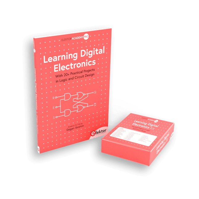
Elektor Bundles Learning Digital Electronics (Bundle)
Digitale Elektronik praxisnah meistern! Dieses Bundle enthält das Buch Learning Digital Electronics mit über 20 praktischen Projekten in Logik- und Schaltungsdesign sowie ein 100-teiliges Starterkit – damit Sie sofort mit dem Bau von Logikschaltungen, Zählern, Displays und mehr beginnen können. Learning Digital Electronics (Buch) Dieses Buch ist ein praktischer Leitfaden zur digitalen Elektronik und behandelt die wesentlichen Komponenten moderner digitaler Systeme: Zahlensysteme, Logikgatter, Boolesche Algebra, kombinatorische und sequentielle Logik und mehr. In über 20 strukturierten Projekten entwerfen und bauen Sie digitale Systeme mit realen Komponenten wie Logikgattern, Multiplexern, Decodern, Flip-Flops, Zählern und Schieberegistern. Die Projekte reichen von einfachen LED-Logikschaltungen bis hin zu digitalen Schlössern, Displaysystemen, Ampelsteuerungen und zeitbasierten Designs. Ausgewählte Projekte führen in die Verwendung von Tools wie CircuitVerse zur Schaltungssimulation ein, während mehrere Designs Logikbausteine der 74HC-Serie verwenden, die häufig im digitalen Hardware-Prototyping verwendet werden. Im Buch finden Sie: Klare Darstellung von Zahlensystemen und Binärarithmetik Grundlagen logischer Gatter und Implementierungen universeller Gatter Schritt-für-Schritt-Projekte mit Flipflops, Zählern und Registern Realwelt-Design mit Logikchips der 74HC-Serie Techniken zum Entwurf kombinatorischer und sequentieller Systeme Dieses Buch verfolgt einen designorientierten, anwendungsorientierten Ansatz für die digitale Elektronik – basierend auf funktionierenden Schaltungen, erprobter Logik und praktischen Experimenten. Learning Digital Electronics (Kit) Dieses Kit wurde speziell entwickelt, um das Buch "Learning Digital Electronics" zu ergänzen. Da alle benötigten Komponenten enthalten sind, können Sie jedes praktische Projekt im Buch direkt durchführen. Inhalt des Kits 2x 74HC08 UND-Gatter-Chip 2x 74HC00 NAND-Gatter-Chip 1x 74HC86 XOR-Gatter-Chip 1x 555 Timer-Chip 1x 74HC161 Zähler-Chip 1x 74HC164 Schieberegister 1x CD4511 7-Segment-Decoder 1x CD4027 JK Flip-Flop 1x BC337 NPN-Transistor 1x KPS-5161 7-Segment-Display mit gemeinsamer Kathode 1x Lichtabhängiger Widerstand (LDR) 4x 10 KΩ Widerstände 8x 1 KΩ Widerstand 2x 47 KΩ Widerstände 1x 100 KΩ Widerstand 4x 2,7 KΩ Widerstände 1x 5,6 KΩ Widerstand 1x 150 KΩ Widerstand 1x 10 μF Kondensator 2x 0,01 μF Kondensator 2x 100 nF Kondensator 8x Kleine rote LED 1x Kleine grüne LED 1x Kleine orangefarbene LED 4x Drucktastenschalter 1x Aktiv-Summer 1x Batteriehalter für 3x AA-Batterien (Batterien nicht im Lieferumfang enthalten) 1x Steckplatine 40x Male-to-male Jumperkabel (Länge: 200 mm)
€ 69,95€ 59,95Bestpreis
-
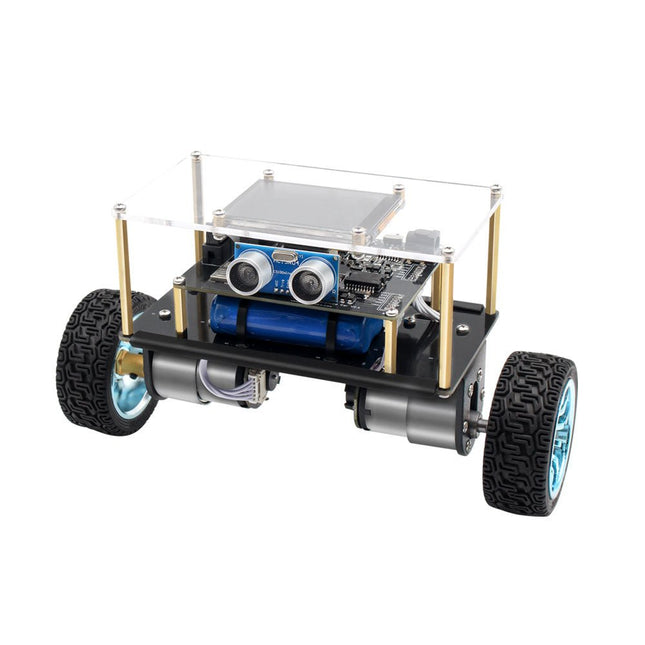
Elektor Labs Elektor Mini-Wheelie Selbstbalancierender Roboter
Der Elektor Mini-Wheelie ist eine experimentelle autonome selbstbalancierende Roboterplattform. Der selbstbalancierende Roboter basiert auf einem ESP32-S3-Mikrocontroller und ist mithilfe der Arduino-Umgebung und Open-Source-Bibliotheken vollständig programmierbar. Dank seiner drahtlosen Fähigkeiten kann er über WLAN, Bluetooth oder ESP-NOW ferngesteuert werden oder mit einem Benutzer oder sogar einem anderen Roboter kommunizieren. Zur Erkennung von Hindernissen steht ein Ultraschallwandler zur Verfügung. Über das Farbdisplay lassen sich niedliche Gesichtsausdrücke oder für den bodenständigeren Nutzer auch kryptische Debug-Meldungen darstellen. Der Roboter wird als Komplettbausatz mit Teilen geliefert, die Sie selbst zusammenbauen müssen. Alles ist dabei, sogar ein Schraubenzieher. Hinweis: Der Mini-Wheelie ist eine pädagogische Entwicklungsplattform, die zum Lernen, Experimentieren und zur Entwicklung von Robotern gedacht ist. Er ist nicht als Kinderspielzeug klassifiziert, und seine Funktionen, Dokumentation und Zielgruppe spiegeln diesen Zweck wider. Das Produkt richtet sich an Studenten, Dozenten und Entwickler, die Robotik, Programmierung und Hardware-Integration in einem pädagogischen Umfeld erforschen möchten. Technische Daten ESP32-S3 Mikrocontroller mit WLAN und Bluetooth MPU6050 6-achsige Inertial Measurement Unit (IMU) Zwei unabhängig gesteuerte 12 V-Elektromotoren mit Drehzahlmesser Ultraschallwandler 2,9" TFT-Farbdisplay (320 x 240) MicroSD-Kartensteckplatz Batterieleistungsmonitor 3S wiederaufladbarer Li-Po-Akku (11,1 V/2200 mAh) Batterieladegerät im Lieferumfang enthalten Arduino-basierte Open-Source-Software Abmessungen (B x L x H): 23 x 8 x 13 cm Lieferumfang 1x ESP32-S3 Mainboard + MPU6050 Modul 1x LCD-Board (2,9 Zoll) 1x Ultraschallsensor 1x Akku (2200 mAh) 1x Batterieladegerät 1x Motorreifen-Set 1x Gehäuseplatine 1x Acrylplatte 1x Schraubendreher 1x Schutzstreifen 1x Flexkabel B (8 cm) 1x Flexkabel A (12 cm) 1x Flexkabel C 4x Kupfersäule A (25 mm) 4x Kupfersäule B (55 mm) 4x Kupfersäule C (5 mm) 2x Kunststoff-Nylonsäule 8x Schrauben A (10 mm) 24x Schrauben B (M3x5) 8x Nüsse 24x Metallscheiben 2x Kabelbinder 1x MicroSD-Karte (32 GB) Downloads Documentation
€ 89,95
Mitglieder: € 80,96
-

Elektor Digital Elektor September/October 2020 (PDF) EN
Elektor Magazine DE September/Oktober 2020 (PDF)
€ 7,50
-

Elektor Bundles Logic Analyzers in Practice (Bundle)
Book: Logic Analyzers in Practice Step-by-step instructions guide you through the analysis of modern protocols such as I²C, SPI, UART, RS-232, NeoPixel, WS28xx, HD44780 and 1-Wire. With the help of numerous experimental circuits based on the Raspberry Pi Pico, Arduino Uno and the Bus Pirate, you will learn the practical application of popular USB logic analyzers. All the experimental circuits presented in this book have been fully tested and are fully functional. The necessary program listings are included – no special programming or electronics knowledge is required for these circuits. The programming languages used are MicroPython and C along with the development environments Thonny and Arduino IDE. This book uses several models of flexible and widely available USB logic analyzers and shows the strengths and weaknesses of each price range. You will learn about the criteria that matter for your work and be able to find the right device for you. Whether Arduino, Raspberry Pi or Raspberry Pi Pico, the example circuits shown allow you to get started quickly with protocol analysis and can also serve as a basis for your own experiments. After reading this book, you will be familiar with all the important terms and contexts, conduct your own experiments, analyze protocols independently, culminating in a comprehensive knowledge set of digital signals and protocols. USB Logic Analyzer (8-ch, 24 MHz) This USB Logic Analyzer is an 8-channel logic analyzer with each input dual purposed for analog data recording. It is perfect for debugging and analyzing signals like I²C, UART, SPI, CAN and 1-Wire. It operates by sampling a digital input connected to a device under test (DUT) at a high sample rate. The connection to the PC is via USB. Specifications Channels 8 digital channels Maximum sampling rate 24 MHz Maximum input voltage 0 V ~ 5 V Operating temperature 0°C ~ 70°C Input impedance 1 MΩ || 10 pF Supported protocols I²C, SPI, UART, CAN, 1-Wire, etc. PC connection USB Dimensions 55 x 28 x 14 mm Downloads Software This bundle contains: Book 'Logic Analyzers in Practice' (normal price: €35) USB Logic Analyzer (8-ch, 24 MHz) (normal price: €20) USB Cable Jumper Wire Ribbon Cable
€ 54,95€ 44,95Bestpreis
-

OWON OWON ADS924A 4-Kanal Oszilloskop (250 MHz)
Die OWON ADS900A-Serie ist ein kompaktes 12-Bit-Digitaloszilloskop mit bis zu 2 GSa/s, 100 MPTS Speicher und 125/250 MHz Bandbreite. Mit seinem 7"-Multitouch-Display, FFT, Protokolldekodierung und integriertem Logikanalysator ermöglicht es eine präzise Signalanalyse für Labor-, Werkstatt- und Feldanwendungen. Technische Daten ADS914A ADS924A Bandwidth (-3 dB) 125 MHz 250 MHz Channels 4 Max. sample rate 2 GSa/s (single-channel) 1 GSa/s (dual-channel) 500 MSa/s (full-channel) DC Gain Accuracy 3% (≤1 mV) 2% (≥2 mV) Max memory depth 100M Vertical resolution 12 bits Relay time accuracy ±25 ppm (typical) Input Impedance 1 MΩ±2%, parallel with20 pF±5 pF Probe Attenuation Coefficient 1.00μX-1M.00X,step by 1-2-5, support custom Trigger type Edge, Video, Pulse, Slope, Runt, Windows, Timeout, Nth, Logic, RS232/UART, I²C, SPI CAN, LIN Bus decoding RS232/UART, I²C, SPI, CAN, LIN Auto measurement Period, Frequency, +Width, -Width, Rise Time, Fall Time, Scr Duty, +Duty,-Duty, Vavg, Vpp, VRMS, Overshoot, Vmax, Vmin, Vtop, CycRms, Vbase, Vamp, Preshoot, Std Dev, +Pulse Cnt, -Pulse Cnt, Rise Cnt, Fall Cnt, Area, Cyc Area, Delay(A↑-B↑), Delay(A↑-B↓), Delay(A↓-B↑), Delay(A↓-B↓), Phase(A↑-B↑) Phase(A↑-B↓), Phase(A↓-B↑), Phase(A↓-B↓), FRR(A↑-B↑), FRF(A↑-B↓) FFR(A↓-B↑), FFF(A↓-B↓), LRR(A↑-B↑), LRF(A↑-B↓), LFR(A↓-B↑), LFF(A↓-B↓) Waveform Math +, -, *, /, &&, ||, ^, !, Intg, Diff, Sqrt, Function operation (Lg / Ln / Exp / Abs / Sine / Cosine / Tan), FFT, FFT rms, User Defined, digital filter (low pass, high pass, band pass, band reject) Frequency counter 6-digit frequency counter Maximum frequency: maximum analog bandwidth of oscilloscope Voltmeter Support DC, AC+DCrms, ACrms, Resolution: 4 digits (ACV/DCV) Logical Analyzer Specifications Number of channels 16 input channels (D0-D15) (D0 to D7, D8 to D15) Max. input voltage ±40V peak CAT I, transient overvoltage 800Vpk Input Impedance 100kΩ, 8 pF Vertical resolution 1 bit Other Communication Interface HDMI, USB device, USB Host, Trig Out (P/F), LAN Display 7 inch (1024x600), capacitive multi-touch screen Power supply interface USB-C Dimensions 260 x 160 x 78 mm Weight 1.5 kg Lieferumfang 1x OWON ADS924A Oszilloskop 1x Netzteil 1x Netzkabel 1x USB-Kabel 1x Sonde 1x Quick Guide Downloads Manual Quick Guide PC Software
€ 677,11
-

FNIRSI FNIRSI SG-003A Signalgenerator
Der FNIRSI SG-003A ist ein kleiner, hochpräziser Signalgenerator mit einem 2,4' TFT-Farbdisplay mit einem Frequenzbereich von bis zu 10 kHz und einem aktiven und passiven Stromausgang von 24 mA. Die maximale Ausgangsspannung beträgt 24 V. Die eingebaute 3000-mAh-Lithiumbatterie hat eine Laufzeit von 10 Stunden. FNIRSI SG-003A wird hauptsächlich für die Fehlersuche in industriellen SPS, Prozessinstrumenten, elektrischen Ventilen usw. verwendet. Features Genauigkeit (Spannung/Strom) 0,1% ±0,005 Auflösung (aktuell) 0,01 mA Frequenz 0-10 kHz Auflösung 5 Ziffern Ausgangsleistung 24 V Display 2,4" TFT-LCD (320 x 240) Abmessungen 92 x 72 x 30 mm Gewicht 165 g Technische Daten Signal Bereich Genauigkeit Auflösung Maximale Belastung Externe Stromversorgung Aktiver Stromausgang 0~24 mA ±(0,1% + 0,005) 0,01 mA 750 Ω Passiver Stromausgang (XMT) 0~24 mA ±(0,1% + 0,005) 0,01 mA 0~30 V Spannungsausgang 0~24 V ±(0,1% + 0,005) 0,01 V 24-V-Schleife 0~24 mA ±(0,1% + 0,005) 0,01 mA Frequenzausgang 0~9999 Hz ±2% 5 Ziffern Stromeingang 0~24 mA ±(0,1% + 0,005) 0,01 mA Spannungseingang 0~30 V ±(0,1% + 0,005) 0,01 V Lieferumfang 1x FNIRSI SG-003A Signalgenerator 4x Testclips 1x USB-Ladegerät 1x USB-C Kabel 1x Manual Downloads Manual Firmware V4.3
€ 68,79
-

Elektor Labs Elektor Rauscharmes Labornetzteil
Das rauscharme Labornetzteil von Elektor ist ein vollständig analoges, einstellbares, symmetrisches Gerät mittlerer Leistung, das ohne Schalt- oder digitale Komponenten auskommt. Es bietet eine Ausgangsspannung, die zwischen 0 V und ±22 V einstellbar ist, sowie einen Ausgangsstrom, der von 0 A bis 1 A eingestellt werden kann. Da auf jegliche Art von Schalttechnik verzichtet wird, liefert das Design extrem geringes Rauschen. Zur Anzeige beider Ausgangsspannungen und -ströme werden vier kleine analoge Einbauinstrumente mit Drehspulmesswerk verwendet. Die meisten modernen Labornetzgeräte und AC-Adapter arbeiten mit Schaltnetzteiltechnik. Selbst die besten Ausführungen weisen zwangsläufig hochfrequente Restwelligkeit und andere Schaltartefakte am Ausgang auf, die die Prüfung empfindlicher analoger Schaltungen stören und Messungen kleiner Signale beeinträchtigen können. Um dieses Problem zu vermeiden, setzt dieses Konzept auf ein vollständig analoges Netzgerät. Obwohl es weniger effizient ist als vergleichbare Schaltnetzteile, spielt die geringere Effizienz beim Einsatz auf dem Prüfstand kaum eine Rolle und sorgt für sauberere und zuverlässigere Messergebnisse. Da viele analoge Schaltungen eine symmetrische Versorgung benötigen, liefert dieses Design positive und negative Ausgangsspannungen gleicher Höhe. Eine geringfügige Nachjustierung ist möglich, um eventuelle Ungleichgewichte auszugleichen. Selbstverständlich ist auch eine einstellbare Strombegrenzung integriert. Das Kit enthält die für den Aufbau des Netzteils erforderlichen Komponenten, mit Ausnahme der Transformatoren. Technische Daten Ausgangsspannung 0…+22 V, 0, −22 V Ausgangsstrom 0…+1 A, 0…−1 A Rauschen −85 dBV (bei 0,95 A/20 V, B = 22 kHz) −84 dBV (bei 0,95 A/20 V, B > 500 kHz) Restwelligkeit 50 µVRMS (bei 950 mA/20 V, B = 22 kHz, hauptsächlich 100-Hz-Anteil) Lieferumfang 3x Platinen: Regler (PCB-1), Netzfilter (PCB-2) und Transformator (PCB-3) Alle Bauteile mit Ausnahme der Netztransformatoren 4x Drehspulmesswerke Zusätzliche Teile für die Verdrahtung (Drähte, Bananenbuchsen, Kaltgeräte-Netzmodul usw.) Nicht enthalten Die drei Netztransformatoren Ein Gehäuse Stückliste Für die Spannungsregler-Platine (240386-1) Widerstände (250 mW, 1%) R1 = 12 Ω R2, R8, R37, R62 = 1 MΩ R3, R7, R10, R13, R17, R20, R22, R30, R35, R42, R45, R47, R55, R60 = 100 Ω, 600 mW R4, R5 = 4.7 kΩ R6 = 100 kΩ R9, R12, R14, R36, R38, R39, R61, R63, R66, R72, R78, R79 = 10.0 kΩ, 600 mW R11 = 9.76 kΩ, 600 mW R15, R40 = 44.2 kΩ, 600 mW R16, R41, R77 = 1 kΩ R18, R43 = 1.5 kΩ, 1 W, 5% R19, R44 = 470 Ω, 1 W, 5% R21, R46 = 330 Ω, 600 mW R23, R24, R48, R49 = 1.0 Ω, 1 W R25, R50 = 1 kΩ, 1 W, 5% R26, R28, R51, R53 = 1.000 kΩ 0.1%, 15 ppm/C R27, R29, R52, R54 = 10.00 kΩ 0.1%, 15 ppm/C R31, R56 = 1.2 kΩ, 1 W, 5% R32, R57 = 47 kΩ R33, R58 = 270 Ω R34, R59 = 27 kΩ R64, R69 = 12.0 kΩ R65 = 3.0 kΩ, 600 mW R67, R80 = 470 Ω, 600 mW R68, R70 = 6.8 kΩ, 600 mW R71 = 30.0 kΩ,, 600 mW R73, R74, R75, R76 = 10 MΩ P1, P2, P3 = 10 kΩ, 200 mW, 20%, potentiometer, 1 turns, single, lin., panel mount P4, P5 = 500 Ω, 500 mW, 10%, trimmer, 25 turns, 3296Y-1-501LF Bourns P6, P7 = 10 kΩ, 500 mW, 10%, trimmer, 25 turns, 3296Y-1-501LF Bourns Kondensatoren C1 = 100 nF, 50 V, 10%, ceramic X7R, LS 5 mm C2, C3, C6, C7, C30 = 10 µF, 63V, 20%, LS 2.5 mm, 3000hours@105°C C4, C5, C8, C9, C13, C14, C18, C19, C23, C24, C28, C29, C31, C32, C38, C39 = 100 nF, 250 V, 10%, PET, LS 7.5 mm C10, C20 = 47 nF, 100 V, 5%, PET, LS 5 mm C11, C21 = 10 nF, 100 V, 5%, PET, LS 5 mm C12, C22 = 220 µF, 35 V, 20%, 0.024 Ω, LS2.5/3.5 mm, Ir 3.4 A, 2000hours@125°C, polymer C15, C25 = 120 µF, 50 V, 20%, ESR 0.02 Ω, Diam. 10 mm max., LS 5 mm C16, C26 = 15 nF, 100 V, 5%, PET, LS 5 mm C17, C27 = 47 nF, 100 V, 5%, PET, LS 5 mm C33, C34 = 22 µF, 50 V, 20%, LS 2 mm, 10000 hours @ 105°C C35, C36, C44, C45 = 1 µF, 100 V, 10%, LS 5 mm, ceramic X7R C37 = 100 uF, 50 V, 20%. LS 3.5 mm C40, C41, C42, C43, C46, C47, C48, C49 = 1000 µF, 50 V, 20%, LS 5/7.5 mm, Ir 3.32 A, 10000hours@105°C, D 16 mm C50, C51, C52, C53 = 47 nF, 100 V, 10%, ceramic X7R, LS 5 mm Induktivitäten L1, L2 = 4.7 µH, 3.2 A, 0.033 Ω, LS 5 mm, RLB0914-4R7ML Bourns L3 = Commom mode choke, 14.5 mH, 3 A, SSRH24NH-30145 Kemet Halbleiter D1, D2, D3, D4, D5, D9, D10, D11, D15 = BAT85, DO-34 D6, D7, D12, D13 = SR560, DO-201AD D8, D14, D16 = 1N4148, DO-35 D17 = Zenerdiode, 5.6 V, 0.5 W, DO-41 D18, D19 = 1N4004, DO-41 D20, D21 D22, D23 = V30100CI-M3/P, dual common cathode, TO-220 D24 = Zener diode, 30 V, 1 W, DO-41 LED1, LED2 = LED, red, T-1 (3 mm) LED3, LED4 = LED, green, T-1 (3 mm) TVS1, TVS2 = BZW50-33B, R6 T1, T2, T4 = BC337.25, TO-92 T3 = NJW0302G, TO-3P T5, T6, T8 = BC327.25, TO-92 T7 = NJW0281G, TO-3P T9 = BD139, TO-126 (SOT-32) IC1 = LM334Z, TO-92 IC2 = LM4040AIZ-5.0/NOPB, TO-92 (TO-226AA-3) IC3, IC4 = OPA2992IDR, SOIC-8 IC5, IC6 = OPA4992IDR, SOIC-14 IC7 = OPA992IDBVR, SOT-23-5 IC8 = LM339N, DIP-14 IC9 = LM317, TO-220 IC10 = LM337, TO-220 Sonstiges F1, F2 = 5×20 mm fuse, 1.6 A, fast acting HS1, HS2 = Heatsink MC33271 (for T3/T7), 2.7°C/W, PCB mount, height 63.5 mm K1, K4 = 3-way screw terminal block, LS 3.5 mm, max. 1.5 mm² K2, K3 = 3-way screw terminal block, LS 3.5 mm, max. 1 mm² M1, M3 = Moving coil meter, Range 30 V, type 91C4, 45×45 mm M2, M4 = Moving coil meter, Range 1 A, type 91C4, 45×45 mm² RE1 = Relay DPDT,5V, UA2-5NU Verschiedenes 3× 3-way screw terminal block, LS 3.5 mm, max. 1 mm² (for P1, P2, P3) 4× Pin header, 1×2, vertical, pitch 2.54 mm (for LED1, LED2, LED3, LED4) 4× Pin socket, 1×2, vertical. pitch 2.54 mm (for LED1, LED2, LED3, LED4) 2× Heatsink FK222SA220, 20°C/W, PCB mount (for IC9 & IC10) 2× Mica thermal pad for TO-220, 12×18×0.05 mm (for IC9 & IC10) 2× Insulating bushing IB 6, TO-220 (for IC9 & IC10) 2× Ceramic thermal pad, 23×20×2 mm (for T3 & T7) 2× PCB Fuse Holder, for 5×20 mm fuse, 10 A (for F1, F2) 2× Cover for PCB Fuse Holder, transparent (for F1, F2) 2× 2-way screw terminal block, LS 3.5 mm, max. 1 mm² (for M1 & M3) 2× 2-way screw terminal block, LS 3.5 mm, max. 1.5 mm² (for M2 & M4) 8× M3 solder lug, thickness 0.35 mm (for M1…M4) M4 solder lug, thickness 0.35 mm (to connect 4 mm banana connectors) Screened cable, 1 pair, 2×24 AWG/0.22 mm², 1 m (for P1, P2 & P3) IC socket, DIP, 14 contacts (for IC8) M3 washer, plain, steel M3 screw, 16 mm, steel, pan head M3 nut M3 spring washer 50 mm M3 standoff, steel, male-female 12 mm M3 standoff, steel, male-female 10 mm M3 standoff, steel, male-female M3 screw, 8 mm, steel, pan head Für die Netzfilter-Platine (240386-2) Widerstand R1 = 220 kΩ, 1 W, 500 V, 5% Kondensatoren C1, C2 = 470 nF, 305 VAC, Class X2, 11 × 27 mm max., LS 15/22.5 mm C3, C4, C5, C6 = 2.2 nF, 300 VAC, Class Y2, 13 × 4 mm, LS 10 mm, PP Induktivitäten L1, L2 = Common-mode choke, 6.8 mH, 1.7 A, TDK B82732R2172B030 Halbleiter MOV1 = TVS varistor, 300 VAC, S14K300 (230 VAC, B72214S0301K101) and SK14K150 (150 VAC, B72214S0151K101) Sonstiges K1, K2 = 3-way screw terminal block, LS 7.62 mm F1 = Time-delay fuse, 0.5 A (230 VAC) or 1 A (115 VAC) Verschiedenes 1× Fuse holder, 5×20 mm, 10 A, 500 VAC 1× Transparent fuse cover 4× 10 mm M3 standoff, steel, male–female 4× M3 screw, 8 mm, steel, pan head 4× M3 nut Für die Transformator-Platine (240386-3) Widerstände R1, R2 = 2.7 kΩ, 600 mW, 1% R3 = 10.0 kΩ, 600 mW, 1% Kondensator C1 = 220 µF, 50 V, 20%, Ø10 mm, LS 5 mm, 4000 h @ 105°C Transformatoren (nicht im Lieferumfang dieses Kits enthalten!) TR1, TR2, TR3 = 2×7 V, 25 VA, PCB-mounted toroid, 70060K Talema Halbleiter D1–D4 = 1N4148, DO-35 D5, D6 = 1N4004, DO-41 D7 = Zener 5.6 V, 1.3 W, DO-41 LED1 = LED, red, T-1 (3 mm) IC1, IC2 = MOC8021M, CTR ≥ 1000%, DIP-6 Sonstiges F1, F2, F3 = 160 mA time-delay fuse (230 VAC) or 315 mA time-delay fuse (115 VAC) K1 = 2-way screw terminal block, LS 7.62 mm K2 = 3-way screw terminal block, LS 3.5 mm, max 1.5 mm² K3, K4 = 3-way screw terminal block, LS 3.5 mm, max 1 mm² RE1, RE2 = Relay DPDT, 5 A/250 VAC / 24 VDC Verschiedenes 1× Pin header 1×2, pitch 2.54 mm + matching socket for LED1 3× Fuse holder 5 × 20 mm, 10 A, 500 VAC + transparent cover 3× M4 screw, 8 mm, pan head + washer for TR1-TR3 8× M3 screw, 8 mm, pan head + nut + washer 8× 10 mm M3 standoff, steel, male–female 2× IC socket, DIP-6 for IC1 & IC2 Weitere Bauteile 1 m red insulated wire, stranded, 1.5 mm² 0.5 m blue insulated wire, stranded, 1.5 mm² 0.5 m black insulated wire, stranded, 1.5 mm², 0.5 m 2 m red insulated wire, stranded, D 0.56 mm (0.25 mm²) 2 m black insulated wire, stranded, D 0.56 mm (0.25 mm²) 0.5 m Multicore Cable, Flexible, 3 Core, 0.75 mm² (24 x 0.2 mm) Red banana socket Black banana socket Blue banana socket Green banana socket IEC Power Entry Module with switch, IEC C14 3 crimp terminals, FASTON, 4.75 x 0.81 mm 3 knobs Links Elektor Labs JumpStarter Page Artikel (Teil 1) Artikel (Teil 2)
€ 249,00
Bestpreis
-

Seeed Studio Seeed Studio RF Explorer WSUB1G+ Slim Spektrum-Analyzer
The Seeed Studio RF Explorer WSUB1G+ is a powerful, high-performance digital spectrum analyzer covering frequencies from 50 kHz to 1 GHz. The Slim model features a robust design, a more conveniently positioned USB connector on the side, and a larger internal battery capacity. Features Internal LNA amplifier and selectable attenuator Low frequency support from 50 KHz covering LF, MF, HF, VHF and UHF up to 960 Mhz New HELP and SET buttons to improve user interface and configuration selection with 2-clicks Wide band coverage to all popular sub-1 Ghz bands, including FM, TV and DTV, ISM, RFID, GSM, etc. Ideal choice for HAM bands from 160 m to 33 cm Pocket size and light weight Solid metal case Spectrum Analyzer mode with Peak Max and Hold, Normal, Overwrite and Averaging modes High capacity internal Lithium battery for 20hs+ of continuous run, rechargeable by USB Multi-platform Windows/Linux/MacOS Open Source software and API libraries Can be extended with internal Expansion Modules for additional band and functionality Technische Daten Frequency band: 0.05 MHz – 960 MHz Frequency span: 0.1 MHz – 960 MHz Internal selectable LNA 25 dB gain Internal selectable Attenuator 30 dB Graphics LCD 128 x 64 pixels, great visibility outdoors Support included for Windows, Linux and MacOS X Backlight for great visibility indoor Internal Lithium Ion 1800 mA/h rechargeable battery Standard SMA 50 Ω connector Wideband 144/433 MHz dual band telescopic antenna included UHF 400-900 MHz rubber duck articulated antenna included Amplitude resolution: 0.5 dBm Dynamic range: -125 dBm to 10 dBm Absolute Max input power: +30 dBm Average noise level (typical LNA): -125 dBm Frequency stability and accuracy (typical): ±10 ppm Amplitude stability and accuracy (typical): ±2 dBm Frequency resolution: 1 kHz Resolution bandwidth (RBW): Automatic 2.6 kHz to 600 kHz Lieferumfang 1x Seeed Studio RF Explorer WSUB1G+ Slim Spectrum Analyzer 1x Mini USB cable 1x Dual band 144/430 MHz Telescopic antenna 1x UHF 400-900 Mhz antenna 1x EVA case
€ 201,11


