
Suchergebnisse für "raspberry OR pi OR high OR quality OR camera OR module"
-

Elektor Labs Elektor Rauscharmes Labornetzteil
Das rauscharme Labornetzteil von Elektor ist ein vollständig analoges, einstellbares, symmetrisches Gerät mittlerer Leistung, das ohne Schalt- oder digitale Komponenten auskommt. Es bietet eine Ausgangsspannung, die zwischen 0 V und ±22 V einstellbar ist, sowie einen Ausgangsstrom, der von 0 A bis 1 A eingestellt werden kann. Da auf jegliche Art von Schalttechnik verzichtet wird, liefert das Design extrem geringes Rauschen. Zur Anzeige beider Ausgangsspannungen und -ströme werden vier kleine analoge Einbauinstrumente mit Drehspulmesswerk verwendet. Die meisten modernen Labornetzgeräte und AC-Adapter arbeiten mit Schaltnetzteiltechnik. Selbst die besten Ausführungen weisen zwangsläufig hochfrequente Restwelligkeit und andere Schaltartefakte am Ausgang auf, die die Prüfung empfindlicher analoger Schaltungen stören und Messungen kleiner Signale beeinträchtigen können. Um dieses Problem zu vermeiden, setzt dieses Konzept auf ein vollständig analoges Netzgerät. Obwohl es weniger effizient ist als vergleichbare Schaltnetzteile, spielt die geringere Effizienz beim Einsatz auf dem Prüfstand kaum eine Rolle und sorgt für sauberere und zuverlässigere Messergebnisse. Da viele analoge Schaltungen eine symmetrische Versorgung benötigen, liefert dieses Design positive und negative Ausgangsspannungen gleicher Höhe. Eine geringfügige Nachjustierung ist möglich, um eventuelle Ungleichgewichte auszugleichen. Selbstverständlich ist auch eine einstellbare Strombegrenzung integriert. Das Kit enthält die für den Aufbau des Netzteils erforderlichen Komponenten, mit Ausnahme der Transformatoren. Technische Daten Ausgangsspannung 0…+22 V, 0, −22 V Ausgangsstrom 0…+1 A, 0…−1 A Rauschen −85 dBV (bei 0,95 A/20 V, B = 22 kHz) −84 dBV (bei 0,95 A/20 V, B > 500 kHz) Restwelligkeit 50 µVRMS (bei 950 mA/20 V, B = 22 kHz, hauptsächlich 100-Hz-Anteil) Lieferumfang 3x Platinen: Regler (PCB-1), Netzfilter (PCB-2) und Transformator (PCB-3) Alle Bauteile mit Ausnahme der Netztransformatoren 4x Drehspulmesswerke Zusätzliche Teile für die Verdrahtung (Drähte, Bananenbuchsen, Kaltgeräte-Netzmodul usw.) Nicht enthalten Die drei Netztransformatoren Ein Gehäuse Stückliste Für die Spannungsregler-Platine (240386-1) Widerstände (250 mW, 1%) R1 = 12 Ω R2, R8, R37, R62 = 1 MΩ R3, R7, R10, R13, R17, R20, R22, R30, R35, R42, R45, R47, R55, R60 = 100 Ω, 600 mW R4, R5 = 4.7 kΩ R6 = 100 kΩ R9, R12, R14, R36, R38, R39, R61, R63, R66, R72, R78, R79 = 10.0 kΩ, 600 mW R11 = 9.76 kΩ, 600 mW R15, R40 = 44.2 kΩ, 600 mW R16, R41, R77 = 1 kΩ R18, R43 = 1.5 kΩ, 1 W, 5% R19, R44 = 470 Ω, 1 W, 5% R21, R46 = 330 Ω, 600 mW R23, R24, R48, R49 = 1.0 Ω, 1 W R25, R50 = 1 kΩ, 1 W, 5% R26, R28, R51, R53 = 1.000 kΩ 0.1%, 15 ppm/C R27, R29, R52, R54 = 10.00 kΩ 0.1%, 15 ppm/C R31, R56 = 1.2 kΩ, 1 W, 5% R32, R57 = 47 kΩ R33, R58 = 270 Ω R34, R59 = 27 kΩ R64, R69 = 12.0 kΩ R65 = 3.0 kΩ, 600 mW R67, R80 = 470 Ω, 600 mW R68, R70 = 6.8 kΩ, 600 mW R71 = 30.0 kΩ,, 600 mW R73, R74, R75, R76 = 10 MΩ P1, P2, P3 = 10 kΩ, 200 mW, 20%, potentiometer, 1 turns, single, lin., panel mount P4, P5 = 500 Ω, 500 mW, 10%, trimmer, 25 turns, 3296Y-1-501LF Bourns P6, P7 = 10 kΩ, 500 mW, 10%, trimmer, 25 turns, 3296Y-1-501LF Bourns Kondensatoren C1 = 100 nF, 50 V, 10%, ceramic X7R, LS 5 mm C2, C3, C6, C7, C30 = 10 µF, 63V, 20%, LS 2.5 mm, 3000hours@105°C C4, C5, C8, C9, C13, C14, C18, C19, C23, C24, C28, C29, C31, C32, C38, C39 = 100 nF, 250 V, 10%, PET, LS 7.5 mm C10, C20 = 47 nF, 100 V, 5%, PET, LS 5 mm C11, C21 = 10 nF, 100 V, 5%, PET, LS 5 mm C12, C22 = 220 µF, 35 V, 20%, 0.024 Ω, LS2.5/3.5 mm, Ir 3.4 A, 2000hours@125°C, polymer C15, C25 = 120 µF, 50 V, 20%, ESR 0.02 Ω, Diam. 10 mm max., LS 5 mm C16, C26 = 15 nF, 100 V, 5%, PET, LS 5 mm C17, C27 = 47 nF, 100 V, 5%, PET, LS 5 mm C33, C34 = 22 µF, 50 V, 20%, LS 2 mm, 10000 hours @ 105°C C35, C36, C44, C45 = 1 µF, 100 V, 10%, LS 5 mm, ceramic X7R C37 = 100 uF, 50 V, 20%. LS 3.5 mm C40, C41, C42, C43, C46, C47, C48, C49 = 1000 µF, 50 V, 20%, LS 5/7.5 mm, Ir 3.32 A, 10000hours@105°C, D 16 mm C50, C51, C52, C53 = 47 nF, 100 V, 10%, ceramic X7R, LS 5 mm Induktivitäten L1, L2 = 4.7 µH, 3.2 A, 0.033 Ω, LS 5 mm, RLB0914-4R7ML Bourns L3 = Commom mode choke, 14.5 mH, 3 A, SSRH24NH-30145 Kemet Halbleiter D1, D2, D3, D4, D5, D9, D10, D11, D15 = BAT85, DO-34 D6, D7, D12, D13 = SR560, DO-201AD D8, D14, D16 = 1N4148, DO-35 D17 = Zenerdiode, 5.6 V, 0.5 W, DO-41 D18, D19 = 1N4004, DO-41 D20, D21 D22, D23 = V30100CI-M3/P, dual common cathode, TO-220 D24 = Zener diode, 30 V, 1 W, DO-41 LED1, LED2 = LED, red, T-1 (3 mm) LED3, LED4 = LED, green, T-1 (3 mm) TVS1, TVS2 = BZW50-33B, R6 T1, T2, T4 = BC337.25, TO-92 T3 = NJW0302G, TO-3P T5, T6, T8 = BC327.25, TO-92 T7 = NJW0281G, TO-3P T9 = BD139, TO-126 (SOT-32) IC1 = LM334Z, TO-92 IC2 = LM4040AIZ-5.0/NOPB, TO-92 (TO-226AA-3) IC3, IC4 = OPA2992IDR, SOIC-8 IC5, IC6 = OPA4992IDR, SOIC-14 IC7 = OPA992IDBVR, SOT-23-5 IC8 = LM339N, DIP-14 IC9 = LM317, TO-220 IC10 = LM337, TO-220 Sonstiges F1, F2 = 5×20 mm fuse, 1.6 A, fast acting HS1, HS2 = Heatsink MC33271 (for T3/T7), 2.7°C/W, PCB mount, height 63.5 mm K1, K4 = 3-way screw terminal block, LS 3.5 mm, max. 1.5 mm² K2, K3 = 3-way screw terminal block, LS 3.5 mm, max. 1 mm² M1, M3 = Moving coil meter, Range 30 V, type 91C4, 45×45 mm M2, M4 = Moving coil meter, Range 1 A, type 91C4, 45×45 mm² RE1 = Relay DPDT,5V, UA2-5NU Verschiedenes 3× 3-way screw terminal block, LS 3.5 mm, max. 1 mm² (for P1, P2, P3) 4× Pin header, 1×2, vertical, pitch 2.54 mm (for LED1, LED2, LED3, LED4) 4× Pin socket, 1×2, vertical. pitch 2.54 mm (for LED1, LED2, LED3, LED4) 2× Heatsink FK222SA220, 20°C/W, PCB mount (for IC9 & IC10) 2× Mica thermal pad for TO-220, 12×18×0.05 mm (for IC9 & IC10) 2× Insulating bushing IB 6, TO-220 (for IC9 & IC10) 2× Ceramic thermal pad, 23×20×2 mm (for T3 & T7) 2× PCB Fuse Holder, for 5×20 mm fuse, 10 A (for F1, F2) 2× Cover for PCB Fuse Holder, transparent (for F1, F2) 2× 2-way screw terminal block, LS 3.5 mm, max. 1 mm² (for M1 & M3) 2× 2-way screw terminal block, LS 3.5 mm, max. 1.5 mm² (for M2 & M4) 8× M3 solder lug, thickness 0.35 mm (for M1…M4) M4 solder lug, thickness 0.35 mm (to connect 4 mm banana connectors) Screened cable, 1 pair, 2×24 AWG/0.22 mm², 1 m (for P1, P2 & P3) IC socket, DIP, 14 contacts (for IC8) M3 washer, plain, steel M3 screw, 16 mm, steel, pan head M3 nut M3 spring washer 50 mm M3 standoff, steel, male-female 12 mm M3 standoff, steel, male-female 10 mm M3 standoff, steel, male-female M3 screw, 8 mm, steel, pan head Für die Netzfilter-Platine (240386-2) Widerstand R1 = 220 kΩ, 1 W, 500 V, 5% Kondensatoren C1, C2 = 470 nF, 305 VAC, Class X2, 11 × 27 mm max., LS 15/22.5 mm C3, C4, C5, C6 = 2.2 nF, 300 VAC, Class Y2, 13 × 4 mm, LS 10 mm, PP Induktivitäten L1, L2 = Common-mode choke, 6.8 mH, 1.7 A, TDK B82732R2172B030 Halbleiter MOV1 = TVS varistor, 300 VAC, S14K300 (230 VAC, B72214S0301K101) and SK14K150 (150 VAC, B72214S0151K101) Sonstiges K1, K2 = 3-way screw terminal block, LS 7.62 mm F1 = Time-delay fuse, 0.5 A (230 VAC) or 1 A (115 VAC) Verschiedenes 1× Fuse holder, 5×20 mm, 10 A, 500 VAC 1× Transparent fuse cover 4× 10 mm M3 standoff, steel, male–female 4× M3 screw, 8 mm, steel, pan head 4× M3 nut Für die Transformator-Platine (240386-3) Widerstände R1, R2 = 2.7 kΩ, 600 mW, 1% R3 = 10.0 kΩ, 600 mW, 1% Kondensator C1 = 220 µF, 50 V, 20%, Ø10 mm, LS 5 mm, 4000 h @ 105°C Transformatoren (nicht im Lieferumfang dieses Kits enthalten!) TR1, TR2, TR3 = 2×7 V, 25 VA, PCB-mounted toroid, 70060K Talema Halbleiter D1–D4 = 1N4148, DO-35 D5, D6 = 1N4004, DO-41 D7 = Zener 5.6 V, 1.3 W, DO-41 LED1 = LED, red, T-1 (3 mm) IC1, IC2 = MOC8021M, CTR ≥ 1000%, DIP-6 Sonstiges F1, F2, F3 = 160 mA time-delay fuse (230 VAC) or 315 mA time-delay fuse (115 VAC) K1 = 2-way screw terminal block, LS 7.62 mm K2 = 3-way screw terminal block, LS 3.5 mm, max 1.5 mm² K3, K4 = 3-way screw terminal block, LS 3.5 mm, max 1 mm² RE1, RE2 = Relay DPDT, 5 A/250 VAC / 24 VDC Verschiedenes 1× Pin header 1×2, pitch 2.54 mm + matching socket for LED1 3× Fuse holder 5 × 20 mm, 10 A, 500 VAC + transparent cover 3× M4 screw, 8 mm, pan head + washer for TR1-TR3 8× M3 screw, 8 mm, pan head + nut + washer 8× 10 mm M3 standoff, steel, male–female 2× IC socket, DIP-6 for IC1 & IC2 Weitere Bauteile 1 m red insulated wire, stranded, 1.5 mm² 0.5 m blue insulated wire, stranded, 1.5 mm² 0.5 m black insulated wire, stranded, 1.5 mm², 0.5 m 2 m red insulated wire, stranded, D 0.56 mm (0.25 mm²) 2 m black insulated wire, stranded, D 0.56 mm (0.25 mm²) 0.5 m Multicore Cable, Flexible, 3 Core, 0.75 mm² (24 x 0.2 mm) Red banana socket Black banana socket Blue banana socket Green banana socket IEC Power Entry Module with switch, IEC C14 3 crimp terminals, FASTON, 4.75 x 0.81 mm 3 knobs Links Elektor Labs JumpStarter Page Artikel (Teil 1) Artikel (Teil 2)
€ 249,00
Bestpreis
-

Elektor Digital Arduino UNO Q and AI (E-book)
Learn to Build Intelligent Embedded Systems Build smarter embedded systems with Arduino UNO Q. This book gives you the tools, knowledge, and confidence to turn ideas into intelligent, working solutions using the Arduino UNO Q platform. Discover how to build intelligent embedded systems with the Arduino UNO Q and AI. Unlock the full potential of the Arduino UNO Q, a next-generation platform that combines the real-time power of the STM32U585 microcontroller with the flexibility of a Qualcomm Dragonwing QRB2210 microprocessor. Learn how to rapidly prototype real-world applications using the Arduino IDE for low-level embedded control and Python in Arduino App Lab for high-level development. Build confidence through hands-on projects that guide you step by step from basic board features to complete working systems. Explore ready-to-use, AI based Arduino App Lab examples and see how they can jump-start your development and reduce time to deployment. Step into the world of Edge AI with a clear, practical introduction to Edge Impulse Studio—no prior AI experience required. Follow a complete, real-world workflow to create a Keyword Spotting AI application, covering data collection, model training, optimization, and on-device inference using the Edge Impulse Studio. Bridge the gap between embedded systems and machine learning and learn how to bring intelligence directly onto your hardware. Perfect for embedded engineers, educators, students, and makers looking to stay ahead in AI-enabled product development.
€ 29,95
Mitglieder: € 26,96
-

Siglent Siglent SDS1104X-U 4-Kanal Oszilloskop (100 MHz)
Die SDS1000X-U-Serie nutzt die SPO-Technologie (Super-Phosphor-Oszilloskop), die eine hervorragende Signaltreue und Leistung bietet. Es verfügt über ein innovatives digitales Triggersystem mit hoher Empfindlichkeit und geringem Jitter sowie einer Wellenform-Erfassungsrate von 400.000 Bildern/Sek. (Sequenzmodus). Der SDS1000X U verfügt außerdem über eine 256-stufige Intensitätsabstufungsanzeigefunktion und einen Farbtemperaturanzeigemodus, der bei anderen Modellen dieser Klasse nicht zu finden ist. Eine weitere leistungsstarke Ergänzung ist die neue 128-k-Punkt-FFT-Mathematikfunktion, die dem SDS1000X-U eine sehr hohe Frequenzauflösung bei der Beobachtung von Signalspektren verleiht. SDS1000X-U unterstützt auch das Suchen und Navigieren. Die Funktionen und die Leistung des neuen SDS1000X-U von SIGLENT sind in dieser Preisklasse einzigartig. Features 100 MHz Bandbreite Echtzeit-Abtastrate bis zu 1 GSa/s Die neueste Generation der SPO-Technologie Wellenformerfassungsraten bis zu 100.000 Wfm/s (Normalmodus) und 400.000 Wfm/s (Sequenzmodus) Unterstützt 256-stufige Intensitätsabstufungs- und Farbtemperatur-Anzeigemodi Aufzeichnungslänge bis zu 14 Mpts Digitales Auslösesystem Intelligenter Trigger: Flanke, Steigung, Impulsbreite, Fenster, Runt, Intervall, Timeout (Dropout), Muster Triggerung und Dekodierung des seriellen Busses (Standard), unterstützt die Protokolle I²C, SPI, UART, CAN, LIN Videoauslöser, unterstützt HDTV 10 Arten von Ein-Tasten-Verknüpfungen, unterstützt Auto-Setup, Standard, Cursor, Messen, Rollen, Verlauf, Anzeigen/Persistieren, Clear Sweep, Zoom und Drucken Der segmentierte Erfassungsmodus (Sequenz) unterteilt die maximale Datensatzlänge in mehrere Segmente (bis zu 80.000), entsprechend den vom Benutzer festgelegten Triggerbedingungen Automatische Messfunktion für 38 Parameter sowie Messstatistik-, Zoom-, Gating-, Mathematik-, Verlaufs- und Referenzfunktionen Funktion zur Aufzeichnung der Verlaufswellenform (History) (maximale aufgezeichnete Wellenformlänge beträgt 80.000 Bilder) 128.000 Punkte FFT, unterstützt Peaks und Markers Mathematische Funktionen (FFT, Addition, Subtraktion, Multiplikation, Division, Integration, Differential, Quadratwurzel) Großes 7-Zoll-TFT-LCD-Display mit einer Auflösung von 800 x 480 Downloads Datasheet Manual Programming Guide
€ 401,00
Bestpreis
-

Elektor Digital Elektor July/August 2025 (PDF) EN
Elektor GREEN and GOLD members can download their digital edition here. Not a member yet? Click here. OBD2 Sensor DashboardOld Dials Sparked a Quest for Real Data OBD2: Add a Rev Counter and Gear Shift Indicator to Your CarRetro, but Super Useful LiDAR and Vision Sensors for Robotics Sensor+Test 2025 and PCIM 2025 Contact-Free E-Field Measurements (1)A Vibrating Membrane for Assessing DC Voltages or Static Electric Fields Wireless Mailbox NotifierFrom Optical Sensors to Radar, Exploring a Few Options Elektor Mini-WheelieA Self-Balancing Robot Solar CellsPeculiar Parts, the Series Getting Started With a Modern Radar SensorIs an Accurate Measurement on Your Radar? From Life’s ExperiencePaper Factory CybersecurityTough Times for Hackers Siglent Presents Next-Gen Multi-Channel OscilloscopesHigh-Performance Solutions for Modern Power and Embedded Systems Bluetooth 6.0 Brings Enhanced Distance-Ranging ApplicationsNew Version Offers Improved Device Positioning and Location Services Exploring Wireless Communication with BeagleY-AI Err-lectronicsCorrections, Updates, and Readers’ Letters Starting Out in Electronics……Concludes the Topic on Opamps A Powerful AI Code AssistantSpeed Up Your Development with Continue and Visual Studio Code Solar Charge Controller with MPPT (2)The Circuit Ultrasonic Obstacle DetectorA Simple Project to Help Those with Impaired Vision 2025: An AI OdysseyMid-Year Review Raspberry Pi Standalone MIDI Synthesizer (3)Making It Smarter and Adding a User Interface Meshtastic: A Demo ProjectAn Intelligent Mesh of LoRa Radios Analog Audio Frequency GeneratorHigh-Quality Adjustable Frequency Sine Wave Generator
€ 7,50
-

Siglent Siglent SDS1204X-E 4-Kanal Oszilloskop (200 MHz)
Das Siglent SDS1204X-E ist ein leistungsstarkes 200-MHz-Vierkanal-Oszilloskop, das auf der gleichen Plattform wie das sehr beliebte SDS1202X-E basiert, jedoch mehrere wesentliche Verbesserungen aufweist, darunter zwei 1-GSa/s-ADCs und zwei 14-Mpt-Speichermodule. Die Wellenform-Erfassungsraten betragen bis zu 100.000 Wfms/s im Normalmodus und 400.000 Wfms/s im Sequenzmodus. Die SDS1000X-E-Zielfernrohre verfügen über ein großes 7-Zoll-Farbdisplay mit 256 Stufen und Funktionen zur Intensitätsabstufung und Farbtemperatur. Technische Daten Bandbreite 200 MHz Abtastrate (max.) 1 GSa/s Kanäle 2CH+EXT 4CH Speichertiefe (max.) 7 Mpts/CH (kein Interleave-Modus); 14 Mpts/CH (Interleave-Modus) Wellenform-Erfassungsrate (max.) 100.000 Wfms/s (Normalmodus), 400.000 Wfms/s (Sequenzmodus) Triggertypen Flanke, Steigung, Impulsbreite, Fenster, Runt, Intervall, Dropout, Muster, Video Serieller Trigger (Standard) I 2 C, SPI, UART/RS232, CAN, LIN Dekodierungstyp (Standard) I 2 C, SPI, UART/RS232, CAN, LIN 16 digitale Kanäle (nur Vierkanalserie, Option) Maximale Wellenform-Erfassungsrate bis zu 1 GSa/s, Aufzeichnungslänge bis zu 14 Mpts/CH USB-AWG-Modul (nur Vierkanalserie, Option) Ein Kanal, 25 MHz, Abtastrate 125 MHz, Wellenlänge 16 kpts Bode-Diagramm (nur Vierkanalserie) Mindeststartfrequenz 10 Hz, Mindestscanbandbreite 500 Hz, maximale Scan-Bandbreite von 120 MHz (abhängig von Oszilloskop und AWG-Bandbreite), 500 maximale Scanfrequenzpunkte USB-WLAN-Adapter (nur Vierkanalserie, Option) 802.11b/g/b, WPA-PSK, der Adapter muss von Siglent geliefert werden, um eine ordnungsgemäße Funktion zu gewährleisten Downloads Datasheet Manual Programming Guide
€ 781,44
Bestpreis
-

Siglent Siglent SDS2102X Plus 2-Kanal Oszilloskop (100 MHz)
Die digitalen Speicheroszilloskope der SDS2000X Plus-Serie von Siglent sind in Bandbreiten von 100 MHz, 200 MHz und 350 MHz erhältlich, haben eine maximale Abtastrate von 2 GSa/s, eine maximale Aufzeichnungslänge von 200 Mpts/Kanal und bis zu 4 analoge Kanäle + 16 digitale Kanäle, Mixed-Signal-Analysefähigkeit. Die SDS2000X Plus-Serie nutzt die SPO-Technologie von Siglent mit einer maximalen Wellenformerfassungsrate von bis zu 120.000 wfm/s (Normalmodus, bis zu 500.000 wfm/s im Sequenzmodus), einer Anzeigefunktion mit 256 Intensitätsstufen sowie einer Farbtemperatur Anzeigemodus. Es verwendet außerdem ein innovatives digitales Triggersystem mit hoher Empfindlichkeit und geringem Jitter. Das Triggersystem unterstützt mehrere leistungsstarke Triggermodi, einschließlich serieller Bus-Triggerung. Verlaufsaufzeichnung von Wellenformen, Sequenzerfassung sowie Such- und Navigationsfunktionen ermöglichen die Erfassung, Speicherung und Analyse erweiterter Wellenformaufzeichnungen. Eine beeindruckende Auswahl an Mess- und Mathematikfunktionen, Optionen für einen 50-MHz-Wellenformgenerator sowie serielle Dekodierung, Maskentest, Bode-Plot und Leistungsanalyse sind weitere Merkmale des SDS2000X Plus. Ein 10-Bit-Erfassungsmodus hilft dabei, Anwendungen zu erfüllen, die eine Auflösung von mehr als 8 Bit erfordern. Der große kapazitive 10,1"-Touchscreen unterstützt Multi-Touch-Gesten, während die Remote-Websteuerung sowie die Unterstützung für Maus und externe Tastatur die Bedieneffizienz des SDS2000X Plus erheblich verbessern. Features Erhältlich mit 100 MHz, 200 MHz, 350 MHz Bandbreite (aufrüstbar auf 500 MHz) Echtzeit-Abtastrate bis zu 2 GSa/s Aufzeichnungslänge bis zu 200 Mpts Serieller Bus-Trigger und Decoder, unterstützt I²C, SPI, UART, CAN, LIN, CAN FD, FlexRay, I²S und MIL-STD-1553B Bietet 10-Bit-Modus, vertikalen und horizontalen Zoom Der kapazitive Touchscreen unterstützt Multi-Touch-Gesten Siglent SDS2000X Plus Oszilloskope SDS2102X Plus SDS2104X Plus SDS2204X Plus SDS2354X Plus Bandbreite 100 MHz 100 MHz 200 MHz 350 MHz Kanäle 2 4 4 4 Echtzeit-Abtastrate 2 GSa/s 2 GSa/s 2 GSa/s 2 GSa/s Erfassungsrate 120,000 wfm/s 120,000 wfm/s 120,000 wfm/s 120,000 wfm/s Speichertiefe 200 Mpts/ch 200 Mpts/ch 200 Mpts/ch 200 Mpts/ch Lieferumfang Siglent SDS2102X Plus Oszilloskop Passive Sonden Netzkabel USB-Kabel Manual Downloads Datasheet Manual Quick guide User manual Firmware
€ 1.069,00€ 855,20Bestpreis
-

Siglent Siglent SDS814X HD 4-Kanal Oszilloskop (100 MHz)
The Siglent SDS814X HD digital storage oscilloscope is based on 2 GSa/s, 12-bit Analog-Digital Converters and front ends with excellent noise floor performance. With a 100 MHz bandwidth, and a maximum record length of 50 Mpts, and the capability to analyze 4 analog channels alongside 16 digital channels, the SDS814X HD is perfectly suited for mixed signal analysis. Features 12-bit High Resolution 12-bit Analog-Digital Convertors with sample rate up to 2 GSa/s Front ends with 70 μVrms noise floor @ 100 MHz bandwidth 2/4 analog channels, up to 700 MHz bandwidth SPO technology Waveform capture rate up to 80,000 wfm/s (normal mode), and 500,000 wfm/s (sequence mode) Supports 256-level intensity grading and color temperature display modes. Up to 50 Mpts record length Digital trigger system Intelligent trigger: Edge, Slope, Pulse width, Window, Runt, Interval, Dropout, Pattern, Video (HDTV supported), Qualified, Nth edge, Delay, Setup/Hold time. Serial bus triggering and decoder, supports protocols I²C, SPI, UART, CAN, LIN. Segmented acquisition (Sequence) mode, dividing the maximum record length into multiple segments (up to 80,000), according to trigger conditions set by the user, with a very small dead time between segments to capture the qualifying event. History waveform record (History) function, the maximum recorded waveform length is 80,000 frames. Automatic measurements on 50+ parameters, supports statistics with histogram, track, trend, Gating measurement, and measurements on Math, History and Ref. 4 Math traces (2 Mpts FFT, addition, subtraction, multiplication, division, integration, differential, square root, etc.), supports formula editor. Abundant data analysis functions such as Search, Navigate, Counter, Bode plot and Power Analysis High Speed hardware-based Mask Test function, with Mask Editor tool for creating user-defined masks 16 digital channels (optional) 25 MHz waveform generator (optional) 7" TFT-LCD display with 1024 x 600 resolution; Capacitive touch screen supports multi-touch gestures. Interfaces include: USB Hosts, USB Device (USBTMC), LAN (VXI-11/Telnet/Socket), Pass/Fail, Trigger Out Built-in web server supports remote control over the LAN port using a web browser. Supports SCPI remote control commands. Supports external mouse and keyboard. Supports NTP. Technische Daten Analog Channels 4 Bandwidth 100 MHz Vertical resolution 12-bit Sample rate (Max.) One channel mode: 2 GSa/sTwo channel mode: 1 GSa/sFour channel mode: 500 MSa/s Memory depth (Max.) One channel mode: 50 Mpts/chTwo channel mode: 25 Mpts/chFour channel mode: 10Mpts/ch Waveform capture rate (Max.) Normal mode: 80,000 wfm/sSequence mode: 500,000 wfm/s Trigger type Edge, Slope, Pulse width, Window, Runt, Interval, Dropout, Pattern, Video, Qualified, Nth edge, Delay, Setup/Hold time, Serial Serial trigger and decode (Standard) I²C, SPI, UART, CAN, LIN Measurement 50+ parameters, statistics, histogram, trend, and track supported Math 4 traces 2 Mpts FFT, Filter, +, -, x, ÷, ∫dt, d/dt, √, Identity, Negation, Absolute, Sign, ex, 10x, ln, lg, Interpolation, MaxHold, MinHold, ERES, Average. Supports formula editor Data analysis Search, Navigate, History, Mask Test, Counter, Bode plot, and Power Analysis Digital channel (optional) 16-channel; maximum sample rate up to 1 GSa/s; record length up to 10 Mpts USB AWG module (option) One channel, 25 MHz, sample rate of 125 MHz, wave length of 16 kpts, isolated output I/O 2x USB 2.0 Host, USB 2.0 Device, 10/100 M LAN, Auxiliary output (TRIG OUT, PASS/FAIL), SBUS (Siglent MSO) Probe (Standard) Passive probe PB470 for each channel Display 7 TFT-LCD with capacitive touch screen (1024x600) Lieferumfang 1x Siglent SDS814X Oscilloscope 4x Passive probe (100 MHz) PP510 1x Power cord (EU) 1x USB cable 1x Certificate of calibration 1x Quick start Downloads Datasheet Manual Programming guide
€ 586,85
Bestpreis
-

Zhongdi ZD-8965 Entlötstation
Die ZD-8965 ist eine digitale temperaturgesteuerte Entlötstation, die mit Erdungsschutz und einem LCD-Display zur Temperaturanzeige ausgestattet ist. Trotz ihres kompakten und robusten Designs lässt sich diese Hochleistungs-Entlötstation einfach mit nur einer Hand bedienen. Die ZD-8965 verfügt über eine Lötpistole mit integriertem Filter, der jegliches abgesaugte Material auffängt und einen kontinuierlichen Betrieb durch einfaches Austauschen der Filter ermöglicht. Darüber hinaus ist in der Spitze ein Temperatursensor eingebettet, der eine schnelle Reaktion auf Temperaturschwankungen für eine konstante Leistung ermöglicht. Features Stellen Sie die Temperatur mühelos zwischen 160°C und 480°C ein, indem Sie die praktischen Auf-/Ab-Tasten auf der Vorderseite verwenden. LED-Anzeige zur Anzeige der Temperatur in °C/°F Verfügt über einen ergonomischen Pistolengriff mit Auslöser für eine schnelle und effiziente Entfernung von Lötzinnabfällen. Die verbesserte Lötpistole verfügt über einen hinteren Abzug, wodurch sie besonders praktisch zum Austauschen und Reinigen von Komponenten ist. Wird mit einer hochwertigen Lötpistole und einer stabilen Halterung geliefert. Ausgestattet mit einer Hochleistungsheizung, die jedes Mal eine optimale Entlötleistung gewährleistet. Technische Daten Station Spannungsversorgung 220-240 V Leistung 140 W Vakuumdruck 600 mm HG Entlötpistole Leistung 140 W (18 V DC)Aufheizleistung: 140 W Temperatur 160-480°C Heizelement Keramikheizung Lieferumfang 1x ZD-8965 Entlötstation 2x Ersatzlötspitze 3x Reinigungsnadel für Entlötspitzen 3x Ersatzfilter für Entlötpistole 1x Ersatzfilter für Lötstation 1x Manual
€ 97,36
-
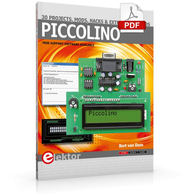
Elektor Digital Piccolino - 30 Projects, mods, hacks and extension (E-book)
The Piccolino rapid development board can be used to design microcontroller circuits quickly. The Piccolino has a fast 16f887 PIC microcontroller, voltage regulator, and communications module, and can be easily extended using its four headers. This e-book contains 30 projects based on the Piccolino. We'll use its unique communications facilities and get the Piccolino to communicate with programs on a PC. On the PC, we use the free programming language Small Basic. You can use this to create Windows programs with buttons and graphs quickly. You will learn how to analyze components such as inductors, capacitors, and OPAMPs, and how to display the measurement results in a graphical format. This will help you to design your circuits easily. We will then start to adapt to the Piccolino. We'll add components to it to make it more powerful, with extra features such as flow control and digital to analog conversion. The clear instructions will enable you to design and build your adaptations. This way you can make your custom designed Piccolino. We'll end up making an extension: a PCB that that can be mounted on the Piccolino headers. As an example, we'll design and build an extension for an LCD. You can use the included board layout to make your PCB or have it made for you. At the same time, you will learn how to make your extensions. The only limitation is your imagination! The clear descriptions along with circuit diagrams and photos, will make the building of these projects an enjoyable experience. Each project has a clear explanation of the reasons why it was designed in a particular way. This helps you learn a lot about the Piccolino, as well as Small Basic, and the components that are used in this e-book. You can adapt the projects to suit your requirements or combine several projects.
€ 34,95
Mitglieder: € 31,46
-

Elektor Digital Elektor Circuit Special 2024 PDF (NL)
Elektor GREEN en GOLD leden kunnen deze uitgave hier downloaden. Nog geen lid? Klik hier om een lidmaatschap af te sluiten. Digitale belasting voor grote stromenvan noodzaak tot innovatie Stemmenroverinstant karaoke-schakeling Audio A/B-keuzeschakelaar met versterkingsregelingschakelt tussen microfoon- en lijningangen Beter laden voor de LIR2032wees lief voor uw knoopcellen Simpele aanraaksensorenmaak ze zelf – voor elke microcontroller Universele infraroodschakelaartweede leven voor oude afstandsbedieningen Microcontroller-gestuurde loeidoosspeelse geluiden met een microcontroller USB-accu-interface Low-power apparaten voeden met een powerbankanti-afschakel-schakeling Kleine klasse-A audioversterker met stroomuitgangstuur luidsprekers aan met stroom in plaats van spanning Pseudo-symmetrische modulehoge CMRR met asymmetrische audioverbindingen Automatische NiMH-laderlaad al uw accu’s in één keer! Thyristorgebaseerde voedingsbeveiliging Schakelaar met vingerafdruk-sensornuttige identiteitscontrole DC/DC-converter voor 3 Aeen upgrade voor vaste-spanningsbronnen Bewaking voor een boilerspannings- en stroomdetectie voor AC-kabels Verzwakkers voor audiosignalen (1)instelbaar met jumpers Poets uw acculader op (1)niet weggooien maar ombouwen! Een print voor ‘de Blauwe’print voor Alps-motorpotmeter met terugkoppeling 50Hz-referentie uit 60Hz-netspanningzo gebruikt u 50Hz-elektronica in 60Hz-landen Digitale isolatoreneenvoudige realisatie van galvanische isolatie Compacte 12W-hifi-monoversterkerklein maar krachtig Zaagtandgenerator met LM386 Driefasen-generatormet Raspberry Pi Pico Deuropener voor muzikaal getalenteerden Elektor-klassieker: Surf Synthesizerzeewatersportachtergrondgeluidgenerator (zwsaggg) Poets uw acculader op (2)niet weggooien maar ombouwen! Lampstroom-monitormet Raspberry Pi Pico Infrarood-telegrafie Fnirsi SWM-10repareer zelf uw accupacks met dit intelligent draagbaar puntlasapparaat Stereo audio-codec voor ESP32 en co.geen angst voor audio-meettechnologie Soldeertechniekendoe het meteen goed! Verzwakkers voor audiosignalen (2)geschakeld met relais USB-C voedingstroom uit USB-C voedingsadapters Drie schakelingen met twee en drie teller-IC’s4017’s werken samen Actieve componenten – de diode Timer voor extreem lange tijdeninstellen en vergeten! Jack in en jack uiteen handige insert-optie voor audioschakelingen ESP32 met één Li-ion-cel Hexadoku
€ 9,95
-

Elektor Januari/Februari 2026 (NL)
Elektor GREEN en GOLD leden kunnen deze uitgave hier downloaden. Nog geen lid? Klik hier om een lidmaatschap af te sluiten. Low-noise laboratorium voeding (1)Een stabiele voedingsbron voor gevoelige circuits STM32 Edge-AI Contest 2025: De winnaars Batterijen van vandaagTechnologie en verschillen in lithiumbatterijen Instelbare elektronische belastingStatische en dynamische DC-belasting Step-down converter van 48 V naar 5 VHet verhaal achter de ontwikkeling van een schakeling Autonome sensornode v2.0Deel 2: Hardware-validatie en vermogensoptimalisatie VaristorenVreemde onderdelen Grafische netfrequentiemeterControleer de kwaliteit van het stroomnet Alle begin......maakt er een eind aan Piekstroombelasting SMD-ferrietenBeter bestand tegen stroompieken Elektor Live! Expert Day 2025 Energy harvesting belooft de implementatie van IoT- en IIoT-toepassingen te zullen versnellenHoe energy harvesting IoT loskoppelt van het stroomnet Fnirsi DPS-150Compacte draagbare voeding en converter Instelbare USB-C voedingsbronMaak van uw USB-C-lader een regelbare voeding Eenvoudige lader en capaciteitstesterMet twee goedkope kant-en-klaar modules Slimme kleurendetector met AI-stem en afspeelfunctie PbMonitor v2.0Overzicht van het vernieuwde accu-bewakingssysteem Een ventilator voor de mini-reflow plateSlimme aanpassingen die de resultaten verbeteren Uit het leven gegrepende tsunami der verwendheid Err-lectronicsCorrecties, updates en lezersbrieven 2026: Een AI-odysseeWanneer modellen de hardware bepalen Precisie pico-ampèremeter (2)Montage, kalibratie en test Draadloze energievoorziening van apparatenMet inductieve technologie Autonoom rijden op basis van AIDe Self Driving Challenge 2024 van de RDW Geluidskaart als signaalgeneratorPC als DCF77-testzender
€ 15,95
-

Siglent Siglent SDS822X HD 2-Kanal Oszilloskop (200 MHz)
The Siglent SDS822X HD digital storage oscilloscope is based on 2 GSa/s, 12-bit Analog-Digital Converters and front ends with excellent noise floor performance. With a 200 MHz bandwidth, and a maximum record length of 100 Mpts, and the capability to analyze 2 analog channels alongside 16 digital channels, the SDS822X HD is perfectly suited for mixed signal analysis. Features 12-bit High Resolution 12-bit Analog-Digital Convertors with sample rate up to 2 GSa/s Front ends with 70 μVrms noise floor @ 200 MHz bandwidth 2/4 analog channels, up to 700 MHz bandwidth SPO technology Waveform capture rate up to 120,000 wfm/s (normal mode), and 500,000 wfm/s (sequence mode) Supports 256-level intensity grading and color temperature display modes. Up to 50 Mpts record length Digital trigger system Intelligent trigger: Edge, Slope, Pulse width, Window, Runt, Interval, Dropout, Pattern, Video (HDTV supported), Qualified, Nth edge, Delay, Setup/Hold time. Serial bus triggering and decoder, supports protocols I²C, SPI, UART, CAN, LIN. Segmented acquisition (Sequence) mode, dividing the maximum record length into multiple segments (up to 80,000), according to trigger conditions set by the user, with a very small dead time between segments to capture the qualifying event. History waveform record (History) function, the maximum recorded waveform length is 80,000 frames. Automatic measurements on 50+ parameters, supports statistics with histogram, track, trend, Gating measurement, and measurements on Math, History and Ref. 4 Math traces (2 Mpts FFT, addition, subtraction, multiplication, division, integration, differential, square root, etc.), supports formula editor. Abundant data analysis functions such as Search, Navigate, Counter, Bode plot and Power Analysis High Speed hardware-based Mask Test function, with Mask Editor tool for creating user-defined masks 16 digital channels (optional) 25 MHz waveform generator (optional) 7" TFT-LCD display with 1024 x 600 resolution; Capacitive touch screen supports multi-touch gestures. Interfaces include: USB Hosts, USB Device (USBTMC), LAN (VXI-11/Telnet/Socket), Pass/Fail, Trigger Out Built-in web server supports remote control over the LAN port using a web browser. Supports SCPI remote control commands. Supports external mouse and keyboard. Supports NTP. Technische Daten Analog Channels 2 Bandwidth 200 MHz Vertical resolution 12-bit Sample rate (Max.) One channel mode: 100 Mpts/chTwo channel mode: Mpts/chFour channel mode: 25 Mpts/ch Memory depth (Max.) One channel mode: 50 Mpts/chTwo channel mode: 25 Mpts/ch Waveform capture rate (Max.) Normal mode: 120,000 wfm/sSequence mode: 500,000 wfm/s Trigger type Edge, Slope, Pulse width, Window, Runt, Interval, Dropout, Pattern, Video, Qualified, Nth edge, Delay, Setup/Hold time, Serial Serial trigger and decode (Standard) I²C, SPI, UART, CAN, LIN Measurement 50+ parameters, statistics, histogram, trend, and track supported Math 4 traces 2 Mpts FFT, Filter, +, -, x, ÷, ∫dt, d/dt, √, Identity, Negation, Absolute, Sign, ex, 10x, ln, lg, Interpolation, MaxHold, MinHold, ERES, Average. Supports formula editor Data analysis Search, Navigate, History, Mask Test, Counter, Bode plot, and Power Analysis Digital channel (optional) 16-channel; maximum sample rate up to 1 GSa/s; record length up to 10 Mpts USB AWG module (option) One channel, 25 MHz, sample rate of 125 MHz, wave length of 16 kpts, isolated output I/O 2x USB 2.0 Host, USB 2.0 Device, 10/100 M LAN, Auxiliary output (TRIG OUT, PASS/FAIL), SBUS (Siglent MSO) Probe (Standard) Passive probe PB470 for each channel Display 7 TFT-LCD with capacitive touch screen (1024x600) Lieferumfang 1x Siglent SDS822X Oscilloscope 2x Passive probe (200 MHz) PP520 1x Power cord (EU) 1x USB cable 1x Certificate of calibration 1x Quick start Downloads Datasheet Manual Programming guide
€ 635,25
Bestpreis


