
Suchergebnisse für "elektor OR archive OR 1974 OR 2023 OR usb OR stick OR en"
-

Great Scott Gadgets Great Scott Gadgets HackRF Pro SDR (100 kHz – 6 GHz) + GRATIS E-Book
AKTION: HackRF Pro bestellen und das neue E-Book "SDR mit HackRF One & HackRF Pro" im Wert von 20 € gratis sichern! HackRF Pro ist das neueste Software Defined Radio (SDR) von Great Scott Gadgets und der leistungsstarke Nachfolger des legendären HackRF One. Mit einem Frequenzbereich von 100 kHz bis 6 GHz deckt es ein enormes Spektrum zum Senden und Empfangen von Funksignalen ab. Als Open-Source-Hardware-Plattform konzipiert, ist das HackRF Pro das ideale Werkzeug für die Analyse und Entwicklung moderner Funktechnologien. Es lässt sich flexibel als USB-Peripheriegerät nutzen oder für den Standalone-Betrieb programmieren. Technische Daten Frequenz: 100 kHz bis 6 GHz Einstellbar von 0 Hz bis 7,1 GHz Halbduplex-Transceiver Bis zu 20 Millionen Abtastungen pro Sekunde 8-Bit-Quadraturabtastung (8-Bit-I und 8-Bit-Q) Kompatibel mit GNU Radio, SDR# und mehr Softwarekonfigurierbare RX- und TX-Verstärkung sowie Basisbandfilter Softwaregesteuerte HF-Port-Leistung (50 mA bei 3,3 V) SMA-HF-Anschluss SMA-Takt-Ein- und -Ausgang für Synchronisation und Triggerung Praktische Tasten zur Programmierung Interne Stiftleisten für Erweiterung High-Speed USB 2.0 mit USB-C Anschluss USB-Stromversorgung Open-Source-Hardware Im Vergleich zu seinem Vorgänger bietet HackRF Pro eine Vielzahl neuer Funktionen, darunter: Erweiterter Betriebsfrequenzbereich Verbesserte HF-Leistung mit flacherem Frequenzgang USB-C Anschluss Integrierter TCXO-Quarzoszillator für überlegene Timingstabilität Logik-Upgrade von einem CPLD zu einem energieeffizienten FPGA Beseitigung von Gleichspannungsspitzen Modus mit erweiterter Präzision und 16-Bit-Abtastwerten für niedrige Abtastraten (typische ENOB: 9-11) Modus mit halber Präzision und 4-Bit-Abtastwerten bei bis zu 40 MS/s Mehr RAM und Flash-Speicher für benutzerdefinierte Firmware Abschirmung des Funkmoduls Trigger-Ein- und -Ausgang über Taktanschlüsse zugänglich Aussparung in der Leiterplatte bietet Platz für zukünftige Erweiterungen Verbessert Energiemanagement Verbesserter HF-Portschutz Funktion zum hardwareseitigen Deaktivieren des Sendemodus Volle Kompatibilität: Dank der bewährten Architektur kann bestehende Software für das HackRF One direkt auch mit dem HackRF Pro genutzt werden. Das HackRF Pro bietet nahtlose Abwärtskompatibilität bei gleichzeitig deutlich gesteigerter Performance. Hinweis: Eine Antenne ist nicht im Lieferumfang enthalten. Wir empfehlen die ANT500 für den optimalen Einstieg. Lieferumfang HackRF Pro SDR mit Kunststoffgehäuse Neues E-Book: SDR mit HackRF One & HackRF Pro (Normalpreis: 20 €) Downloads Documentation GitHub
€ 489,00€ 429,00Bestpreis
-

FNIRSI 65 W USB-C PD GaN Ladegerät
Mit diesem 65 W USB-C PD Netzteil (mit GaN-Technologie) können Sie den FNIRSI HS-01 Lötkolben sofort verwenden. Natürlich können Sie mit diesem Charger auch Ihre Tablets und Smartphones über USB-C und USB-A schnell aufladen. Lieferumfang 65 W USB-C PD GaN Netzteil (EU)
€ 24,59
-

Red Pitaya Red Pitaya STEMlab 125-14 PRO Gen 2 Starter Kit (inkl. Buch)
Dieses Bundle enthält das Red Pitaya STEMlab 125-14 PRO Gen 2 Starter Kit und das neue Buch "Experimenting with Red Pitaya STEMlab Gen 2". Das Red Pitaya STEMlab 125-14 PRO Gen 2 Starter Kit ist eine leistungsstarke und flexible Plattform für Signalverarbeitung, Datenerfassung und elektronische Messanwendungen. Dieses Kit wurde für Ingenieure, Entwickler, Forscher und Dozenten konzipiert und bietet alles, was für den Einstieg in die Entwicklung fortschrittlicher Mess- und Steuerungssysteme erforderlich ist. Das Herzstück des Kits ist das STEMlab 125-14 PRO Gen 2-Board, eine verbesserte und ultraleichte Entwicklungsplatine. Angetrieben vom Xilinx Zynq-7010 SoC mit 512 MB RAM kombiniert es die Programmierbarkeit eines FPGAs mit der Rechenleistung eines ARM-Prozessors, um leistungsstarke Messtechnik und kundenspezifische Signalverarbeitungslösungen zu ermöglichen. Das Board bietet eine 14-Bit-ADC- und DAC-Auflösung, eine Abtastrate von 125 MS/s, einen Eingangsbereich von ±20 V und eine Bandbreite von bis zu 60 MHz. Dank seines verbesserten rauscharmen analogen Frontends, der USB-C-Konnektivität und des kompakten Designs eignet es sich für anspruchsvolle Anwendungen wie HF-Entwicklung, Radarsysteme, Photonikforschung, Software-Defined Radio (SDR) und industrielle Automatisierung. Das Starter Kit enthält alles notwendige Zubehör für den sofortigen Einsatz: eine microSD-Karte mit vorinstalliertem Betriebssystem, ein Netzteil, ein Ethernet-Kabel für den Fernzugriff, zwei 100-MHz-Oszilloskop-Messspitzen sowie SMA-zu-BNC-Adapter für flexible Signalanschlüsse. Das Red Pitaya STEMlab 125-14 PRO Gen 2 Starter Kit ist eine hervorragende Plattform für Rapid Prototyping, FPGA-Entwicklung, Messtechnik und fortgeschrittene Elektronikversuche. Features 14-Bit-ADC- und DAC-Auflösung Abtastrate: 125 MS/s Eingangsspannungsbereich: ±20 V Bandbreite: Bis zu 60 MHz Xilinx Zynq-7010 SoC (FPGA + ARM-Prozessor) 512 MB RAM Rauscharme analoge Front- und Backends Anwendungen HF-Entwicklung und -Test Radar- und drahtlose Systeme Software Defined Radio (SDR) Photonik und optische Forschung Industrielle Automatisierungs- und Steuerungssysteme Signalanalyse und -instrumentierung Schnelles Prototyping elektronischer Bauteile Messsysteme Technische Daten Prozessor Dual-Core ARM Cortex-A9 FPGA AMD Xilinx Zynq-7010 SoC RAM 512 MB (4 Gb) Speicher microSD-Karte (bis zu 32 GB) Betriebssystem Linux-basiertes Red Pitaya OS ADC-Auflösung 14 Bit DAC Auflösung 14 Bit Bandbreite 60 MHz (DC) Abtastrate 125 MS/s Analoge Eingangskanäle 2 Analoge Ausgangskanäle 2 Eingangsspannungsbereich ±1 V (LV) / ±20 V (HV) Eingangsimpedanz 1 MΩ / 10 pF Ausgangsspannungsbereich ±1 V Ethernet 1x Gigabit Ethernet (RJ45) USB 2x USB-C 2.0 (für Stromversorgung und Konsole) Digitale Ein-/Ausgänge 16x GPIO (3,3 V) Kommunikationsschnittstellen I²C, SPI, UART, CAN Stromversorgung 5 V/3 A über USB-C Abmessungen 106,8 x 60,0 x 17,9 mm Lieferumfang 1x Red Pitaya STEMlab 125-14 PRO Gen 2 Board 2x 100-MHz-Oszilloskop-Tastköpfe 2x SMA-zu-BNC-Adapter 1x microSD-Karte mit vorinstalliertem Betriebssystem 1x USB-C-Netzteil 1x Ethernet-Kabel Downloads Documentation Schematics Buch: Experimenting with Red Pitaya STEMlab Gen 2 Mit diesem neuen Buch geht Red Pitaya über ein vielseitiges Board hinaus – es wird zu einem leistungsstarken Laborinstrument für präzise Messungen, Analysen und Steuerungen. Von den Grundlagen der Entwicklung elektronischer Projekte über Überwachung, Regelung und Design bis hin zu Tests führt Sie dieses Buch Schritt für Schritt durch alles, was Sie wissen müssen, um das volle Potenzial der Red Pitaya-Hardware und -Software auszuschöpfen. Das Buch stellt Echtzeitprojekte auf FPGA-Basis vor, die auf einem PC mit der Vivado-Umgebung entwickelt und anschließend zur Ausführung und zum Testen auf die Red Pitaya übertragen werden. Sie lernen mehr über gesteigerte Leistung, erweiterte I/O-Möglichkeiten, verbesserte FPGA-Funktionen sowie fortschrittliche Konnektivitätsoptionen, die neue Möglichkeiten für präzise Messungen, Überwachung und Steuerung in Ihren Embedded-Anwendungen eröffnen. Im Buch entdecken Sie: Einen tiefgehenden Einblick in die Red Pitaya-Architektur und das Hardware-Design Elektronische Experimente mit Red Pitaya für Mess- und Überwachungsanwendungen Praxisnahe Projekte mit der Programmiersprache Python Praktische Anleitungen zur FPGA-Programmierung mit Red Pitaya Red Pitaya FPGA-Projekte mit Verilog HDL in der Vivado IDE Die praxisorientierte Entwicklung elektronischer Projekte inklusive Messung und Tests Schritt-für-Schritt-Beispiele, die Theorie und reale Umsetzung miteinander verbinden Ganz gleich, ob Sie eigene elektronische Schaltungen entwerfen, Werkzeuge zur Signalanalyse entwickeln oder Echtzeit-Steuerungs- und Überwachungssysteme erstellen – dieses Buch vermittelt Ihnen das nötige Wissen und die Sicherheit, um die Red Pitaya-Plattform vollständig zu verstehen und individuell anzupassen.
€ 799,00
Bestpreis
-
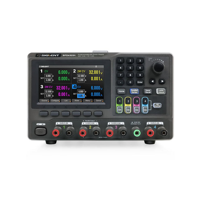
Siglent Siglent SPD4323X 4-Kanal Netzteil (240 W)
The Siglent SPD4323X is a 4-channel DC Linear Programmable Power Supply equipped with a 4.3-inch TFT-LCD display, friendly human-machine interface, and excellent performance indicators. Real-time waveform display provides engineers with an informative user interface. SPD4323X offers a total output power of 240 W with a resolution of 1 mV/1 mA. The maximum voltage and current for each channel are as follows: CH1: 6 V/3.2 A CH2: 32 V/3.2 A CH3: 32 V/3.2 A CH4: 6 V/3.2 A Features Rated output power: 240 W Rated voltage: 32 V, 12 V, 30 V Up to four high-precision power supplies with independent controllable outputs, supporting CH2 and CH3 series and parallel connections Clear graphical interface with waveform and timer display modes 5-digit voltage and current display with minimum resolution of 1 mV, 1 mA Fast output response time: <50us The high current channel support remote voltage compensation sense function. The maximum compensation voltage is 0.6 V Overvoltage protection and overcurrent protection or safe and accurate operation Equipped with a 4.3-inch TFT-LCD display (480 x 272 resolution) USB and LAN standard communication USB-GPIB module is optional Excellent channel density with up to 4 channels in a 3U half rack package Internal data storage for setups and parameters Embedded Web Server with instrument communication that doesn’t require software installation Fully SCPI programming command set support as well as a LabView driver for remote control and system automation Technische Daten SPD4323X SPD4121X SPD4306X Channel Output CH1: Voltage 0 to 6 V Current 0 to 3.2 ACH2: Voltage 0 to 32 V Current 0 to 3.2 ACH3: Voltage 0 to 32 V Current 0 to 3.2 ACH4: Voltage 0 to 6 V Current 0 to 3.2 A CH1: Voltage 0 to 15 V Current 0 to 1.5 ACH2: Voltage 0 to 12 V Current 0 to 10 ACH3: Voltage 0 to 12 V Current 0 to 10 ACH4: Voltage 0 to 15 V Current 0 to 1.5 A CH1: Voltage 0 to 15 V Current 0 to 1.5 ACH2: Voltage 0 to 30 V Current 0 to 6 ACH3: Voltage 0 to 30 V Current 0 to 6 ACH4: Voltage 0 to 15 V Current 0 to 1 A Resolution 1 mV, 1 mA 1 mV, 1 mA 1 mV, 1 mA Setting Accuracy Voltage: ±(0.03% of reading+10) mV, Current: ±(0.3% of reading+10) mA Voltage: ±(0.03% of reading+10) mV, Current: ±(0.3% of reading+10) mA Voltage: ±(0.03% of reading+10) mV, Current: ±(0.3% of reading+10) mA Readback Accuracy Voltage: ±(0.03% of reading+10) mV, Current: ±(0.3% of reading+10) mA Voltage: ±(0.03% of reading+10) mV, Current: ±(0.3% of reading+10) mA Voltage: ±(0.03% of reading+10) mV, Current: ±(0.3% of reading+10) mA Display 4.3" TFT-LCD 5-digit voltage and current display 4.3" TFT-LCD 5-digit voltage and current display 4.3" TFT-LCD 5-digit voltage and current display Output power 240 W 285 W 400 W Lieferumfang 1x Siglent SPD4323X Power Supply 1x Power cord (EU) 1x Output test cord (3 A) 1x USB cable 1x Quick start guide Downloads Datasheet Manual Quick start
€ 762,30
Bestpreis
-
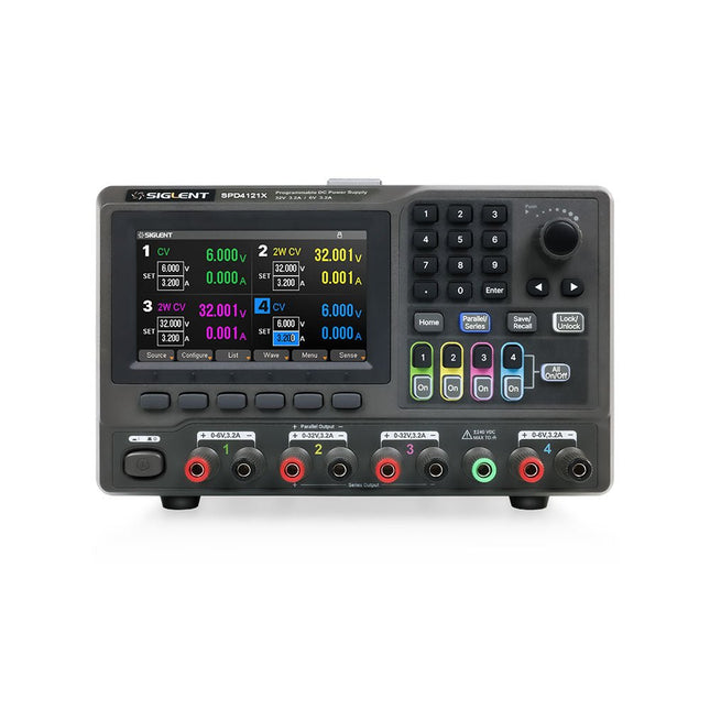
Siglent Siglent SPD4121X 4-Kanal Netzteil (285 W)
The Siglent SPD4121X is a 4-channel DC Linear Programmable Power Supply equipped with a 4.3-inch TFT-LCD display, friendly human-machine interface, and excellent performance indicators. Real-time waveform display provides engineers with an informative user interface. SPD4121X offers a total output power of 285 W with a resolution of 1 mV/1 mA. The maximum voltage and current for each channel are as follows: CH1: 15 V/1.5 A CH2: 12 V/10 A CH3: 12 V/10 A CH4: 15 V/1.5 A Features Rated output power: 285 W Rated voltage: 32 V, 12 V, 30 V Up to four high-precision power supplies with independent controllable outputs, supporting CH2 and CH3 series and parallel connections Clear graphical interface with waveform and timer display modes 5-digit voltage and current display with minimum resolution of 1 mV, 1 mA Fast output response time: <50us The high current channel support remote voltage compensation sense function. The maximum compensation voltage is 0.6 V Overvoltage protection and overcurrent protection or safe and accurate operation Equipped with a 4.3-inch TFT-LCD display (480 x 272 resolution) USB and LAN standard communication USB-GPIB module is optional Excellent channel density with up to 4 channels in a 3U half rack package Internal data storage for setups and parameters Embedded Web Server with instrument communication that doesn’t require software installation Fully SCPI programming command set support as well as a LabView driver for remote control and system automation Technische Daten SPD4323X SPD4121X SPD4306X Channel Output CH1: Voltage 0 to 6 V Current 0 to 3.2 ACH2: Voltage 0 to 32 V Current 0 to 3.2 ACH3: Voltage 0 to 32 V Current 0 to 3.2 ACH4: Voltage 0 to 6 V Current 0 to 3.2 A CH1: Voltage 0 to 15 V Current 0 to 1.5 ACH2: Voltage 0 to 12 V Current 0 to 10 ACH3: Voltage 0 to 12 V Current 0 to 10 ACH4: Voltage 0 to 15 V Current 0 to 1.5 A CH1: Voltage 0 to 15 V Current 0 to 1.5 ACH2: Voltage 0 to 30 V Current 0 to 6 ACH3: Voltage 0 to 30 V Current 0 to 6 ACH4: Voltage 0 to 15 V Current 0 to 1 A Resolution 1 mV, 1 mA 1 mV, 1 mA 1 mV, 1 mA Setting Accuracy Voltage: ±(0.03% of reading+10) mV, Current: ±(0.3% of reading+10) mA Voltage: ±(0.03% of reading+10) mV, Current: ±(0.3% of reading+10) mA Voltage: ±(0.03% of reading+10) mV, Current: ±(0.3% of reading+10) mA Readback Accuracy Voltage: ±(0.03% of reading+10) mV, Current: ±(0.3% of reading+10) mA Voltage: ±(0.03% of reading+10) mV, Current: ±(0.3% of reading+10) mA Voltage: ±(0.03% of reading+10) mV, Current: ±(0.3% of reading+10) mA Display 4.3" TFT-LCD 5-digit voltage and current display 4.3" TFT-LCD 5-digit voltage and current display 4.3" TFT-LCD 5-digit voltage and current display Output power 240 W 285 W 400 W Lieferumfang 1x Siglent SPD4121X Power Supply 1x Power cord (EU) 1x Output test cord (3 A) 1x USB cable 1x Quick start guide Downloads Datasheet Manual Quick start
€ 871,20
Bestpreis
-

Siglent Siglent SPD4306X 4-Kanal Netzteil (400 W)
The Siglent SPD4306X is a 4-channel DC Linear Programmable Power Supply equipped with a 4.3-inch TFT-LCD display, friendly human-machine interface, and excellent performance indicators. Real-time waveform display provides engineers with an informative user interface. SPD4306X offers a total output power of 400 W with a resolution of 1 mV/1 mA. The maximum voltage and current for each channel are as follows: CH1: 15 V/1.5 A CH2: 30 V/6 A CH3: 30 V/6 A CH4: 15 V/1 A Features Rated output power: 400 W Rated voltage: 32 V, 12 V, 30 V Up to four high-precision power supplies with independent controllable outputs, supporting CH2 and CH3 series and parallel connections Clear graphical interface with waveform and timer display modes 5-digit voltage and current display with minimum resolution of 1 mV, 1 mA Fast output response time: <50us The high current channel support remote voltage compensation sense function. The maximum compensation voltage is 0.6 V Overvoltage protection and overcurrent protection or safe and accurate operation Equipped with a 4.3-inch TFT-LCD display (480 x 272 resolution) USB and LAN standard communication USB-GPIB module is optional Excellent channel density with up to 4 channels in a 3U half rack package Internal data storage for setups and parameters Embedded Web Server with instrument communication that doesn’t require software installation Fully SCPI programming command set support as well as a LabView driver for remote control and system automation Technische Daten SPD4323X SPD4121X SPD4306X Channel Output CH1: Voltage 0 to 6 V Current 0 to 3.2 ACH2: Voltage 0 to 32 V Current 0 to 3.2 ACH3: Voltage 0 to 32 V Current 0 to 3.2 ACH4: Voltage 0 to 6 V Current 0 to 3.2 A CH1: Voltage 0 to 15 V Current 0 to 1.5 ACH2: Voltage 0 to 12 V Current 0 to 10 ACH3: Voltage 0 to 12 V Current 0 to 10 ACH4: Voltage 0 to 15 V Current 0 to 1.5 A CH1: Voltage 0 to 15 V Current 0 to 1.5 ACH2: Voltage 0 to 30 V Current 0 to 6 ACH3: Voltage 0 to 30 V Current 0 to 6 ACH4: Voltage 0 to 15 V Current 0 to 1 A Resolution 1 mV, 1 mA 1 mV, 1 mA 1 mV, 1 mA Setting Accuracy Voltage: ±(0.03% of reading+10) mV, Current: ±(0.3% of reading+10) mA Voltage: ±(0.03% of reading+10) mV, Current: ±(0.3% of reading+10) mA Voltage: ±(0.03% of reading+10) mV, Current: ±(0.3% of reading+10) mA Readback Accuracy Voltage: ±(0.03% of reading+10) mV, Current: ±(0.3% of reading+10) mA Voltage: ±(0.03% of reading+10) mV, Current: ±(0.3% of reading+10) mA Voltage: ±(0.03% of reading+10) mV, Current: ±(0.3% of reading+10) mA Display 4.3" TFT-LCD 5-digit voltage and current display 4.3" TFT-LCD 5-digit voltage and current display 4.3" TFT-LCD 5-digit voltage and current display Output power 240 W 285 W 400 W Lieferumfang 1x Siglent SPD4306X Power Supply 1x Power cord (EU) 1x Output test cord (3 A) 1x USB cable 1x Quick start guide Downloads Datasheet Manual Quick start
€ 1.101,10
Bestpreis
-

Elektor Digital Programming Microcontrollers in MicroPython (E-book)
With Examples for Raspberry Pi Pico and ESP32 Creating and programming small electronic systems is now easier than ever before. With inexpensive development boards and modern software tools, anyone curious about embedded design can quickly move from an idea to a working piece of hardware. At the heart of this change is MicroPython—a clear, interactive, and beginner-friendly way to program microcontrollers while still remaining closely connected to the underlying electronics. This book introduces embedded programming through MicroPython on popular platforms such as the Raspberry Pi Pico and the ESP32. You will discover how to use microcontrollers for reading inputs, processing data, and controlling outputs in a predictable, real-time loop. With just a few lines of code, you can blink LEDs, read sensors, drive motors, and communicate with the outside world. The interactive REPL programming interface encourages experimentation and fast learning, making concepts tangible from the very first chapter. While different boards offer different capabilities, they all share the same core principles. Timers, GPIO, analog I/O, PWM, interrupts, and communication interfaces form the foundation of every embedded system. By focusing on these universal building blocks, this book helps you build skills that transfer across platforms and scale naturally toward more advanced development. Whether you are a beginner or an experienced programmer entering embedded systems, you will find that working with MicroPython is both practical and genuinely enjoyable.
€ 24,95
Mitglieder: € 22,46
-

NXP Semiconductors NXP FRDM-MCXN947 Development Board
The FRDM-MCXN947 is a compact and versatile development board designed for rapid prototyping with MCX N94 and N54 microcontrollers. It features industry-standard headers for easy access to the MCU's I/Os, integrated open-standard serial interfaces, external flash memory, and an onboard MCU-Link debugger. Technische Daten Microcontroller MCX-N947 Dual Arm Cortex-M33 cores @ 150 MHz each with optimized performance efficiency, up to 2 MB dual-bank flash with optional full ECC RAM, External flash Accelerators: Neural Processing Unit, PowerQuad, Smart DMA, etc. Memory Expansion *DNP Micro SD card socket Connectivity Ethernet Phy and connector HS USB-C connectors SPI/I²C/UART connector (PMOD/mikroBUS, DNP) WiFi connector (PMOD/mikroBUS, DNP) CAN-FD transceiver Debug On-board MCU-Link debugger with CMSIS-DAP JTAG/SWD connector Sensor P3T1755 I³C/I²C Temp Sensor, Touch Pad Expansion Options Arduino Header (with FRDM expansion rows) FRDM Header FlexIO/LCD Header SmartDMA/Camera Header Pmod *DNP mikroBUS User Interface RGB user LED, plus Reset, ISP, Wakeup buttons Lieferumfang 1x FRDM-MCXN947 Development Board 1x USB-C Cable 1x Quick Start Guide Downloads Datasheet Block diagram
-

Great Scott Gadgets Great Scott Gadgets HackRF One SDR (1 MHz – 6 GHz)
Neue Version verfügbar! Hier klicken! HackRF One ist ein Software Defined Radio (SDR) mit USB-Anschluss, das Funksignale von 1 MHz bis 6 GHz senden und empfangen kann. HackRF One erlaubt den Test und die Entwicklung moderner Funktechnologien der nächsten Generation und ist eine Open-Source-Hardware-Plattform, die auch für den Stand-alone-Betrieb programmiert werden kann. Technische Daten 1 MHz bis 6 GHz Betriebsfrequenz Halbduplex-Transceiver Bis zu 20 Millionen Abtastungen pro Sekunde 8-Bit-Quadraturabtastungen (8-Bit I und 8-Bit Q) Kompatibel mit GNU Radio, SDR und mehr Software-konfigurierbare RX- und TX-Verstärkung und Basisbandfilter Software-gesteuerte Antennenanschlussleistung (50 mA bei 3,3 V) SMA-Antennenbuchse SMA-Buchse für Taktein- und -ausgang zur Synchronisation Bequeme Tasten für die Programmierung Interne Stiftleisten für Erweiterungen Hi-Speed USB 2.0 USB-Stromversorgung Open-Source-Hardware HackRF One ist ein Testgerät für RF-Systeme. Er wurde nicht auf die Einhaltung von Vorschriften zur Übertragung von Funksignalen getestet. Sie sind für die legale Verwendung Ihres HackRF One verantwortlich. Lieferumfang 1x HackRF One SDR 1x Kunststoffgehäuse 1x micro-USB-Kabel Hinweis: Eine Antenne ist nicht im Lieferumfang enthalten. Wir empfehlen die Einsteiger-Teleskopantenne ANT500. Downloads Documentation GitHub Source code and Hardware design files
-

SunFounder SunFounder Kepler Kit (Ultimate Starter Kit für Raspberry Pi Pico W)
Ihr Einstieg in die IoT- und Mikrocontroller-Programmierung Mit über 450 Komponenten und 117 Online-Projekten beflügelt dieses umfassende Kit Ihre Kreativität. Die Tutorials von Paul McWhorter machen das Lernen sowohl für Anfänger als auch für Fortgeschrittene angenehm. Dieses Kit unterstützt MicroPython, C/C++ und Piper Make und bietet vielfältige Programmieroptionen. Entdecken Sie Sensoren, Aktoren, LEDs und LCDs für endlose Projektmöglichkeiten. Von der Heimautomation bis zur Robotik unterstützt dieses Kit Ihre technische Reise. Features IoT-Starterkit für Anfänger: Dieses Kit bietet eine reichhaltige IoT-Lernerfahrung für Anfänger. Mit über 450 Komponenten, 117 Projekten und von Experten geleiteten Videolektionen macht dieses Kit das Erlernen der Mikrocontroller-Programmierung und des IoT ansprechend und leicht zugänglich. Von Experten geleitete Video-Lektionen: Das Kit enthält 27 Video-Tutorials des renommierten Pädagogen Paul McWhorter. Sein engagierter Stil vereinfacht komplexe Konzepte und sorgt so für ein effektives Lernerlebnis in der Mikrocontroller-Programmierung. Große Auswahl an Hardware: Das Kit enthält eine Vielzahl von Komponenten wie Sensoren, Aktoren, LEDs, LCDs und mehr, sodass Sie mit dem Raspberry Pi Pico W experimentieren und eine Vielzahl von Projekten erstellen können. Unterstützt mehrere Sprachen: Das Kit bietet Vielseitigkeit mit Unterstützung für drei Programmiersprachen – MicroPython, C/C++ und Piper Make – und bietet so ein abwechslungsreiches Programmier-Lernerlebnis. Dedizierter Support: Profitieren Sie von unserer fortlaufenden Unterstützung, einschließlich eines Community-Forums und zeitnaher technischer Hilfe für ein nahtloses Lernerlebnis. Lieferumfang Raspberry Pi Pico W Breadboard Überbrückungsdrähte Widerstand Transistor Kondensator Diode Li-Po-Lademodul 74HC595 TA6586 – Motortreiberchip LED RGB-LED LED-Balkendiagramm 7-Segment-Anzeige 4-stellige 7-Segment-Anzeige LED-Punktmatrix I²C LCD1602 WS2812 RGB 8 LED-Streifen Summer Gleichstrommotor Servo DC-Wasserpumpe Relais Schaltfläche Mikroschalter Schiebeschalter Potentiometer Infrarotempfänger Joystick-Modul 4x4-Tastatur MPR121-Modul MFRC522-Modul Fotowiderstand Thermistor Neigungsschalter Reed-Schalter PIR-Bewegungssensormodul Wasserstandsensormodul Ultraschallmodul DHT11 Feuchtigkeitssensor MPU6050-Modul Dokumentation Online-Tutorials in 3 Sprachen (DE, EN und JP)


