
Suchergebnisse für "raspberry OR pi OR 500 OR us"
-

Elektor Digital Elektor November/December 2023 (PDF)
Elektor GREEN and GOLD members can download their digital edition here. Not a member yet? Click here. The Raspberry Pi 5A Huge Improvement From Its Predecessor AI in the Electronics LabGoogle Bard and Flux Copilot Put to the Test Arduino Nano Waveform GeneratorNano + Code = Function Generator Solar-Powered Christmas GarlandAn Eco-Friendly Solution for Garnishing Your Balcony USB Killer DetectorBetter Safe Than Sorry A Simple CNCed EnclosureWith Autodesk Fusion 360 for Personal Use Low-Volume Board ProductionWith and without Assembly IoT Simulation Simplified with WokwiDeveloper Uri Shaked on Design, Software, and More A Bare-Metal Programming Guide (Part 3)CMSIS Headers, Automatic Testing, and a Web Server LoRa, a Swiss Army Knife (2)The Hardware and Software MEMS Microphone Design and Construction Tools to Try Before You SolderSimulation and 3D Modeling Tools That Can Be Used for Free New Tools From Microchip!PICkit 5 and MPLAB ICD 5 Available Now! Rapid Prototyping of Flexible, Stretchable ElectronicsHow the Voltera NOVA Speeds Up Innovation in Wearable Electronic Systems Galvanic IsolationUsing Phototransistor Optocouplers Successfully The Complex Solution or the Anybus Solution?Embedded Industrial Ethernet in 2 Days Rather Than Many Months Your Essential DFM ChecklistHow to Start Designing for Manufacture 3D Printing FilamentsTypes, Features and Use in Prototyping Specialists for Effective Signal Analysis from ELF to EHF BandAaronia’s latest real-time SPECTRAN® V6 series spectrum analyzers Challenges of DFM Analysis for Flex and Rigid-Flex Design Setting Up an SMT Line The Right Combination for a Reliable Assembly Revolutionizing IndustriesThe Rise of Autonomous Mobile Robots (AMRs) Evolved for More ChallengesRohde & Schwarz Adds Eight-Channel R&S MXO 5 to Next-Generation Oscilloscopes Starting Out in Electronics……Amplifying Differences Mini Reflow PlateFor Assembling or Repairing Small SMD Circuits Don’t Start with a Prototype – Start with a Pretotype!Check That a Market Exists for Your Product Before Warming Your Soldering Iron 2023: An AI OdysseyGetting Help Designing a Physical Project Brussels Is InnovatingSupport for Deep Tech
€ 7,50
-
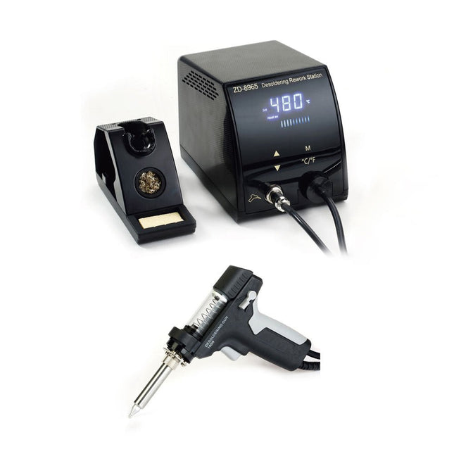
Zhongdi ZD-8965 Entlötstation
Die ZD-8965 ist eine digitale temperaturgesteuerte Entlötstation, die mit Erdungsschutz und einem LCD-Display zur Temperaturanzeige ausgestattet ist. Trotz ihres kompakten und robusten Designs lässt sich diese Hochleistungs-Entlötstation einfach mit nur einer Hand bedienen. Die ZD-8965 verfügt über eine Lötpistole mit integriertem Filter, der jegliches abgesaugte Material auffängt und einen kontinuierlichen Betrieb durch einfaches Austauschen der Filter ermöglicht. Darüber hinaus ist in der Spitze ein Temperatursensor eingebettet, der eine schnelle Reaktion auf Temperaturschwankungen für eine konstante Leistung ermöglicht. Features Stellen Sie die Temperatur mühelos zwischen 160°C und 480°C ein, indem Sie die praktischen Auf-/Ab-Tasten auf der Vorderseite verwenden. LED-Anzeige zur Anzeige der Temperatur in °C/°F Verfügt über einen ergonomischen Pistolengriff mit Auslöser für eine schnelle und effiziente Entfernung von Lötzinnabfällen. Die verbesserte Lötpistole verfügt über einen hinteren Abzug, wodurch sie besonders praktisch zum Austauschen und Reinigen von Komponenten ist. Wird mit einer hochwertigen Lötpistole und einer stabilen Halterung geliefert. Ausgestattet mit einer Hochleistungsheizung, die jedes Mal eine optimale Entlötleistung gewährleistet. Technische Daten Station Spannungsversorgung 220-240 V Leistung 140 W Vakuumdruck 600 mm HG Entlötpistole Leistung 140 W (18 V DC)Aufheizleistung: 140 W Temperatur 160-480°C Heizelement Keramikheizung Lieferumfang 1x ZD-8965 Entlötstation 2x Ersatzlötspitze 3x Reinigungsnadel für Entlötspitzen 3x Ersatzfilter für Entlötpistole 1x Ersatzfilter für Lötstation 1x Manual
€ 97,36
-

Elektor Digital Elektor July/August 2025 (PDF) EN
Elektor GREEN and GOLD members can download their digital edition here. Not a member yet? Click here. OBD2 Sensor DashboardOld Dials Sparked a Quest for Real Data OBD2: Add a Rev Counter and Gear Shift Indicator to Your CarRetro, but Super Useful LiDAR and Vision Sensors for Robotics Sensor+Test 2025 and PCIM 2025 Contact-Free E-Field Measurements (1)A Vibrating Membrane for Assessing DC Voltages or Static Electric Fields Wireless Mailbox NotifierFrom Optical Sensors to Radar, Exploring a Few Options Elektor Mini-WheelieA Self-Balancing Robot Solar CellsPeculiar Parts, the Series Getting Started With a Modern Radar SensorIs an Accurate Measurement on Your Radar? From Life’s ExperiencePaper Factory CybersecurityTough Times for Hackers Siglent Presents Next-Gen Multi-Channel OscilloscopesHigh-Performance Solutions for Modern Power and Embedded Systems Bluetooth 6.0 Brings Enhanced Distance-Ranging ApplicationsNew Version Offers Improved Device Positioning and Location Services Exploring Wireless Communication with BeagleY-AI Err-lectronicsCorrections, Updates, and Readers’ Letters Starting Out in Electronics……Concludes the Topic on Opamps A Powerful AI Code AssistantSpeed Up Your Development with Continue and Visual Studio Code Solar Charge Controller with MPPT (2)The Circuit Ultrasonic Obstacle DetectorA Simple Project to Help Those with Impaired Vision 2025: An AI OdysseyMid-Year Review Raspberry Pi Standalone MIDI Synthesizer (3)Making It Smarter and Adding a User Interface Meshtastic: A Demo ProjectAn Intelligent Mesh of LoRa Radios Analog Audio Frequency GeneratorHigh-Quality Adjustable Frequency Sine Wave Generator
€ 7,50
-

Elektor Labs Elektor Rauscharmes Labornetzteil
Das rauscharme Labornetzteil von Elektor ist ein vollständig analoges, einstellbares, symmetrisches Gerät mittlerer Leistung, das ohne Schalt- oder digitale Komponenten auskommt. Es bietet eine Ausgangsspannung, die zwischen 0 V und ±22 V einstellbar ist, sowie einen Ausgangsstrom, der von 0 A bis 1 A eingestellt werden kann. Da auf jegliche Art von Schalttechnik verzichtet wird, liefert das Design extrem geringes Rauschen. Zur Anzeige beider Ausgangsspannungen und -ströme werden vier kleine analoge Einbauinstrumente mit Drehspulmesswerk verwendet. Die meisten modernen Labornetzgeräte und AC-Adapter arbeiten mit Schaltnetzteiltechnik. Selbst die besten Ausführungen weisen zwangsläufig hochfrequente Restwelligkeit und andere Schaltartefakte am Ausgang auf, die die Prüfung empfindlicher analoger Schaltungen stören und Messungen kleiner Signale beeinträchtigen können. Um dieses Problem zu vermeiden, setzt dieses Konzept auf ein vollständig analoges Netzgerät. Obwohl es weniger effizient ist als vergleichbare Schaltnetzteile, spielt die geringere Effizienz beim Einsatz auf dem Prüfstand kaum eine Rolle und sorgt für sauberere und zuverlässigere Messergebnisse. Da viele analoge Schaltungen eine symmetrische Versorgung benötigen, liefert dieses Design positive und negative Ausgangsspannungen gleicher Höhe. Eine geringfügige Nachjustierung ist möglich, um eventuelle Ungleichgewichte auszugleichen. Selbstverständlich ist auch eine einstellbare Strombegrenzung integriert. Das Kit enthält die für den Aufbau des Netzteils erforderlichen Komponenten, mit Ausnahme der Transformatoren. Technische Daten Ausgangsspannung 0…+22 V, 0, −22 V Ausgangsstrom 0…+1 A, 0…−1 A Rauschen −85 dBV (bei 0,95 A/20 V, B = 22 kHz) −84 dBV (bei 0,95 A/20 V, B > 500 kHz) Restwelligkeit 50 µVRMS (bei 950 mA/20 V, B = 22 kHz, hauptsächlich 100-Hz-Anteil) Lieferumfang 3x Platinen: Regler (PCB-1), Netzfilter (PCB-2) und Transformator (PCB-3) Alle Bauteile mit Ausnahme der Netztransformatoren 4x Drehspulmesswerke Zusätzliche Teile für die Verdrahtung (Drähte, Bananenbuchsen, Kaltgeräte-Netzmodul usw.) Nicht enthalten Die drei Netztransformatoren Ein Gehäuse Stückliste Für die Spannungsregler-Platine (240386-1) Widerstände (250 mW, 1%) R1 = 12 Ω R2, R8, R37, R62 = 1 MΩ R3, R7, R10, R13, R17, R20, R22, R30, R35, R42, R45, R47, R55, R60 = 100 Ω, 600 mW R4, R5 = 4.7 kΩ R6 = 100 kΩ R9, R12, R14, R36, R38, R39, R61, R63, R66, R72, R78, R79 = 10.0 kΩ, 600 mW R11 = 9.76 kΩ, 600 mW R15, R40 = 44.2 kΩ, 600 mW R16, R41, R77 = 1 kΩ R18, R43 = 1.5 kΩ, 1 W, 5% R19, R44 = 470 Ω, 1 W, 5% R21, R46 = 330 Ω, 600 mW R23, R24, R48, R49 = 1.0 Ω, 1 W R25, R50 = 1 kΩ, 1 W, 5% R26, R28, R51, R53 = 1.000 kΩ 0.1%, 15 ppm/C R27, R29, R52, R54 = 10.00 kΩ 0.1%, 15 ppm/C R31, R56 = 1.2 kΩ, 1 W, 5% R32, R57 = 47 kΩ R33, R58 = 270 Ω R34, R59 = 27 kΩ R64, R69 = 12.0 kΩ R65 = 3.0 kΩ, 600 mW R67, R80 = 470 Ω, 600 mW R68, R70 = 6.8 kΩ, 600 mW R71 = 30.0 kΩ,, 600 mW R73, R74, R75, R76 = 10 MΩ P1, P2, P3 = 10 kΩ, 200 mW, 20%, potentiometer, 1 turns, single, lin., panel mount P4, P5 = 500 Ω, 500 mW, 10%, trimmer, 25 turns, 3296Y-1-501LF Bourns P6, P7 = 10 kΩ, 500 mW, 10%, trimmer, 25 turns, 3296Y-1-501LF Bourns Kondensatoren C1 = 100 nF, 50 V, 10%, ceramic X7R, LS 5 mm C2, C3, C6, C7, C30 = 10 µF, 63V, 20%, LS 2.5 mm, 3000hours@105°C C4, C5, C8, C9, C13, C14, C18, C19, C23, C24, C28, C29, C31, C32, C38, C39 = 100 nF, 250 V, 10%, PET, LS 7.5 mm C10, C20 = 47 nF, 100 V, 5%, PET, LS 5 mm C11, C21 = 10 nF, 100 V, 5%, PET, LS 5 mm C12, C22 = 220 µF, 35 V, 20%, 0.024 Ω, LS2.5/3.5 mm, Ir 3.4 A, 2000hours@125°C, polymer C15, C25 = 120 µF, 50 V, 20%, ESR 0.02 Ω, Diam. 10 mm max., LS 5 mm C16, C26 = 15 nF, 100 V, 5%, PET, LS 5 mm C17, C27 = 47 nF, 100 V, 5%, PET, LS 5 mm C33, C34 = 22 µF, 50 V, 20%, LS 2 mm, 10000 hours @ 105°C C35, C36, C44, C45 = 1 µF, 100 V, 10%, LS 5 mm, ceramic X7R C37 = 100 uF, 50 V, 20%. LS 3.5 mm C40, C41, C42, C43, C46, C47, C48, C49 = 1000 µF, 50 V, 20%, LS 5/7.5 mm, Ir 3.32 A, 10000hours@105°C, D 16 mm C50, C51, C52, C53 = 47 nF, 100 V, 10%, ceramic X7R, LS 5 mm Induktivitäten L1, L2 = 4.7 µH, 3.2 A, 0.033 Ω, LS 5 mm, RLB0914-4R7ML Bourns L3 = Commom mode choke, 14.5 mH, 3 A, SSRH24NH-30145 Kemet Halbleiter D1, D2, D3, D4, D5, D9, D10, D11, D15 = BAT85, DO-34 D6, D7, D12, D13 = SR560, DO-201AD D8, D14, D16 = 1N4148, DO-35 D17 = Zenerdiode, 5.6 V, 0.5 W, DO-41 D18, D19 = 1N4004, DO-41 D20, D21 D22, D23 = V30100CI-M3/P, dual common cathode, TO-220 D24 = Zener diode, 30 V, 1 W, DO-41 LED1, LED2 = LED, red, T-1 (3 mm) LED3, LED4 = LED, green, T-1 (3 mm) TVS1, TVS2 = BZW50-33B, R6 T1, T2, T4 = BC337.25, TO-92 T3 = NJW0302G, TO-3P T5, T6, T8 = BC327.25, TO-92 T7 = NJW0281G, TO-3P T9 = BD139, TO-126 (SOT-32) IC1 = LM334Z, TO-92 IC2 = LM4040AIZ-5.0/NOPB, TO-92 (TO-226AA-3) IC3, IC4 = OPA2992IDR, SOIC-8 IC5, IC6 = OPA4992IDR, SOIC-14 IC7 = OPA992IDBVR, SOT-23-5 IC8 = LM339N, DIP-14 IC9 = LM317, TO-220 IC10 = LM337, TO-220 Sonstiges F1, F2 = 5×20 mm fuse, 1.6 A, fast acting HS1, HS2 = Heatsink MC33271 (for T3/T7), 2.7°C/W, PCB mount, height 63.5 mm K1, K4 = 3-way screw terminal block, LS 3.5 mm, max. 1.5 mm² K2, K3 = 3-way screw terminal block, LS 3.5 mm, max. 1 mm² M1, M3 = Moving coil meter, Range 30 V, type 91C4, 45×45 mm M2, M4 = Moving coil meter, Range 1 A, type 91C4, 45×45 mm² RE1 = Relay DPDT,5V, UA2-5NU Verschiedenes 3× 3-way screw terminal block, LS 3.5 mm, max. 1 mm² (for P1, P2, P3) 4× Pin header, 1×2, vertical, pitch 2.54 mm (for LED1, LED2, LED3, LED4) 4× Pin socket, 1×2, vertical. pitch 2.54 mm (for LED1, LED2, LED3, LED4) 2× Heatsink FK222SA220, 20°C/W, PCB mount (for IC9 & IC10) 2× Mica thermal pad for TO-220, 12×18×0.05 mm (for IC9 & IC10) 2× Insulating bushing IB 6, TO-220 (for IC9 & IC10) 2× Ceramic thermal pad, 23×20×2 mm (for T3 & T7) 2× PCB Fuse Holder, for 5×20 mm fuse, 10 A (for F1, F2) 2× Cover for PCB Fuse Holder, transparent (for F1, F2) 2× 2-way screw terminal block, LS 3.5 mm, max. 1 mm² (for M1 & M3) 2× 2-way screw terminal block, LS 3.5 mm, max. 1.5 mm² (for M2 & M4) 8× M3 solder lug, thickness 0.35 mm (for M1…M4) M4 solder lug, thickness 0.35 mm (to connect 4 mm banana connectors) Screened cable, 1 pair, 2×24 AWG/0.22 mm², 1 m (for P1, P2 & P3) IC socket, DIP, 14 contacts (for IC8) M3 washer, plain, steel M3 screw, 16 mm, steel, pan head M3 nut M3 spring washer 50 mm M3 standoff, steel, male-female 12 mm M3 standoff, steel, male-female 10 mm M3 standoff, steel, male-female M3 screw, 8 mm, steel, pan head Für die Netzfilter-Platine (240386-2) Widerstand R1 = 220 kΩ, 1 W, 500 V, 5% Kondensatoren C1, C2 = 470 nF, 305 VAC, Class X2, 11 × 27 mm max., LS 15/22.5 mm C3, C4, C5, C6 = 2.2 nF, 300 VAC, Class Y2, 13 × 4 mm, LS 10 mm, PP Induktivitäten L1, L2 = Common-mode choke, 6.8 mH, 1.7 A, TDK B82732R2172B030 Halbleiter MOV1 = TVS varistor, 300 VAC, S14K300 (230 VAC, B72214S0301K101) and SK14K150 (150 VAC, B72214S0151K101) Sonstiges K1, K2 = 3-way screw terminal block, LS 7.62 mm F1 = Time-delay fuse, 0.5 A (230 VAC) or 1 A (115 VAC) Verschiedenes 1× Fuse holder, 5×20 mm, 10 A, 500 VAC 1× Transparent fuse cover 4× 10 mm M3 standoff, steel, male–female 4× M3 screw, 8 mm, steel, pan head 4× M3 nut Für die Transformator-Platine (240386-3) Widerstände R1, R2 = 2.7 kΩ, 600 mW, 1% R3 = 10.0 kΩ, 600 mW, 1% Kondensator C1 = 220 µF, 50 V, 20%, Ø10 mm, LS 5 mm, 4000 h @ 105°C Transformatoren (nicht im Lieferumfang dieses Kits enthalten!) TR1, TR2, TR3 = 2×7 V, 25 VA, PCB-mounted toroid, 70060K Talema Halbleiter D1–D4 = 1N4148, DO-35 D5, D6 = 1N4004, DO-41 D7 = Zener 5.6 V, 1.3 W, DO-41 LED1 = LED, red, T-1 (3 mm) IC1, IC2 = MOC8021M, CTR ≥ 1000%, DIP-6 Sonstiges F1, F2, F3 = 160 mA time-delay fuse (230 VAC) or 315 mA time-delay fuse (115 VAC) K1 = 2-way screw terminal block, LS 7.62 mm K2 = 3-way screw terminal block, LS 3.5 mm, max 1.5 mm² K3, K4 = 3-way screw terminal block, LS 3.5 mm, max 1 mm² RE1, RE2 = Relay DPDT, 5 A/250 VAC / 24 VDC Verschiedenes 1× Pin header 1×2, pitch 2.54 mm + matching socket for LED1 3× Fuse holder 5 × 20 mm, 10 A, 500 VAC + transparent cover 3× M4 screw, 8 mm, pan head + washer for TR1-TR3 8× M3 screw, 8 mm, pan head + nut + washer 8× 10 mm M3 standoff, steel, male–female 2× IC socket, DIP-6 for IC1 & IC2 Weitere Bauteile 1 m red insulated wire, stranded, 1.5 mm² 0.5 m blue insulated wire, stranded, 1.5 mm² 0.5 m black insulated wire, stranded, 1.5 mm², 0.5 m 2 m red insulated wire, stranded, D 0.56 mm (0.25 mm²) 2 m black insulated wire, stranded, D 0.56 mm (0.25 mm²) 0.5 m Multicore Cable, Flexible, 3 Core, 0.75 mm² (24 x 0.2 mm) Red banana socket Black banana socket Blue banana socket Green banana socket IEC Power Entry Module with switch, IEC C14 3 crimp terminals, FASTON, 4.75 x 0.81 mm 3 knobs Links Elektor Labs JumpStarter Page Artikel (Teil 1) Artikel (Teil 2)
€ 299,00€ 249,00Bestpreis
-

Elektor Digital Elektor Juli/August 2022 (PDF)
Testeur audio à prix modéré Et avec une base logique sur PC et une interface audio USB Fréquencemètre secteur CA Contrôler la fréquence et la tension du secteur Inductancemètre très simple Une tenue facile à porter Lévitation avec ondes acoustiques Un aperçu du kit de lévitation acoustique de Makerfabs Démarrer en électronique? Les redresseurs E-FFWD : regardons à nouveau vers l'avenir ! Débutant avec son oscilloscope Suivez le guide pour parcourir les boutons et molettes Radio logique MSF utilisant un Raspberry Pi Pico Décodeur à signal temporel à logique radio (SDR) basé sur le RPi Pico Capteurs d'humidité pour systèmes d'arrosage Arrosage automatique Nouvelle donne dans les instruments de test et mesure L'innovation des petits acteurs Infographie 07-08/2022 L?inspiration, c?est ça qui compte Entretien avec Walter Arkesteijn, l'entreprise InnoFaith Beauty Sciences et lecteur d'Elektor Minimiser les interférences CEM même avec le stockage Création d'interfaces graphiques et Python avec guide : Jeu de Morpion Relais Reed Drôles de composants ESR-mètre analogique simple et précis en galvanomètre en cadre mobile Feu tricolore pour CO2, connecté à Sigfox N'oubliez pas de vérifier le WiFi ! Femmes de technologie « On juge au mérite, jusqu'à ce que le mérite ait des seins. » Tablette oscilloscope ADS1013D à petit prix Bon rapport qualité/prix ? Dissection des prix intelligents Lesquelles peut-on ouvrir ? Impédance et capacité de la peau Petites expériences Sur le vif Nul n'est prophète en son pays Prise en main du Pokit Meter Couteau suisse pour la mesure Hexadoku Casse-tête pour électriciens
€ 10,95
-

Elektor Digital MicroPython für Mikrocontroller (PDF)
Die Programmiersprache „Python“ hat in den letzten Jahren einen enormen Aufschwung erlebt. Nicht zuletzt haben verschiedene Einplatinensysteme wie der Raspberry Pi zu deren Bekanntheitsgrad beigetragen. Aber auch in anderen Gebieten, wie der Künstlichen Intelligenz oder dem Machine Learning, hat Python weite Verbreitung gefunden. Es ist daher naheliegend, Python bzw. die Variante „MicroPython“ auch für den Einsatz in SoCs (Systems on Chip) zu verwenden. Leistungsfähige Controller wie der ESP32 der Firma Espressif Systems bieten eine hervorragende Performance sowie Wi-Fi- und Bluetooth-Funktionalität zu einem günstigen Preis. Mit diesen Eigenschaften wurde die Maker-Szene im Sturm erobert. Im Vergleich zu anderen Controllern weist der ESP32 einen deutlich größeren Flash und SRAM-Speicher, sowie eine wesentlich höhere CPU-Geschwindigkeit auf. Aufgrund dieser Leistungsmerkmale eignet sich der Chip nicht nur für klassische C-Anwendungen, sondern insbesondere auch für die Programmierung mit MicroPython. Das vorliegende Buch führt in die Anwendung der modernen Ein-Chip-Systeme ein. Neben den technischen Hintergründen steht vor allem MicroPython selbst im Vordergrund. Nach der Einführung in die Sprache werden die erlernten Programmierkenntnisse umgehend in die Praxis umgesetzt. Die einzelnen Projekte sind sowohl für den Einsatz im Labor als auch für Alltagsanwendungen geeignet. Neben dem eigentlichen Lerneffekt steht also auch die Freude am Aufbau kompletter und nützlicher Geräte im Vordergrund. Durch die Verwendung von Laborsteckboards können Schaltungen aller Art mit geringem Aufwand realisiert werden, sodass das Austesten der selbstgebauten Geräte zum lehrreichen Vergnügen wird. Durch die verschiedenen Anwendungen wie Wetterstationen, Digitalvoltmeter, Ultraschall-Entfernungsmesser, RFID-Kartenleser oder Funktionsgeneratoren sind die vorgestellten Projekte auch für Praktika oder Fach- und Studienarbeiten in den Naturwissenschaften bzw. im Natur- und Technikunterricht bestens geeignet.
€ 32,80
Mitglieder: € 29,52
-

Elektor Digital Elektor November/Dezember 2021 (PDF)
TRAITEMENT D'IMAGES AVEC LE KIT JETSON NANO DE NVIDIA2e partie : reconnaissance d'imagesELEKTOR JUMPSTARTER – DU NOUVEAUCampagnes à venirTRACEUR GPS À CODE SOURCE OUVERTTraccar cartographie les déplacements de véhicules, sans recours à un serveur tiers du nuageTESTEUR MULTIFONCTION LCR-T7 DE JOY-ITTest de semi-conducteurs passifs, discrets et de télécommandes IRSYNTHÉTISEUR DE BRUITDu bruit à la musique avec le PRBSynth1DÉMARRER EN ÉLECTRONIQUE…Easier than Imagined! ... Continuing with the CoilVOYAGE DANS LES RÉSEAUX NEURONAUX (2E PARTIE)Les neurones logiquesPROBLÈMES DE SÉCURITÉ ? COMBATTEZ LE FEU PAR LE FEU !Extension à mémoire analogique, protégée par ampoule de flash, pour la boîte à témoin d'effractionKIT DU LCR-MÈTRE 2 MHZ D'ELEKTORBALISES BLUETOOTH : LA PRATIQUEGéolocalisation intra murosC PROGRAMMING ON RASPBERRY PIExtrait : communiquer par Wi-FiTEST DE PRÉCONFORMITÉ CEM POUR UN PROJET ALIMENTÉ EN COURANT CONTINUPartie 2 : le matériel et son utilisationPROPELLER 2 DE PARALLAX (5)La fonction de « broche intelligente »MODBUS SANS FIL (PARTIE 1)Matériel et programmationJUNIOR COMPUTEREn forme après 40 ans de sommeilCONSTRUIRE SON PROPRE ÉTALONNEUR DE HAUTE PRÉCISION−10 V à +10 V, 0 à 40 mA, 0,001 %ARDUINO NANO RP2040 CONNECT EN DÉTAILRaspberry Pi RP2040 + Wi-Fi + BluetoothLE CORPS PHYSIQUE DE L'INTELLIGENCE ARTIFICIELLEPROJET 2.0corrections, mises à jour et courriers des lecteursCRÉATION D'INTERFACES GRAPHIQUES EN PYTHON AVEC GUIZEROInstallez la bibliothèque Python guizero et créez vos propres interfaces graphiques.KIT DE MESURE DU CO2 POUR SALLE DE CLASSEMontage à base d'ESP8266, conçu par l'Université des Sciences Appliquées d'Aix-la-ChapelleMK484, RADIORÉTRO PO/GO...Toujours le plaisir de construire !60 ANS D'ELEKTORQue la lumière soit !HEXADOKUThe Original Elektorized Sudoku
€ 10,95
-

Elektor Publishing Experimenting with Red Pitaya STEMlab Gen 2
Practical Projects and Programs With Experimenting with Red Pitaya STEMlab Gen 2, Red Pitaya goes beyond a versatile board. It becomes a powerful laboratory instrument for precision measurement, analysis, and control. From the fundamentals of electronic project development, monitoring, control, and design to testing, this book walks you step-by-step through everything you need to know to harness the full potential of Red Pitaya hardware and software. The book presents real-time, FPGA-based projects that are developed on a PC using the Vivado environment, then transferred to the Red Pitaya for execution and testing. You will learn about enhanced performance, expanded I/O capabilities, improved FPGA features, and advanced connectivity options that open up new frontiers for precision measurement, monitoring, and control in your embedded applications. Inside the book you will discover: A deep dive into Red Pitaya architecture and hardware design Electronic experiments using Red Pitaya for measurement and monitoring Hands-on projects using the Python programming language Practical guidance for FPGA programming using Red Pitaya Red Pitaya FPGA projects using the Verilog HDL under Vivado IDE Practical design of electronic projects including measurement and testing Step-by-step examples that bridge theory and real-world implementation Whether you are designing your own electronic circuits, developing signal analysis tools, or creating real-time control or monitoring systems, this book provides you the knowledge and confidence you need to fully learn and customize the Red Pitaya platform.
€ 39,95€ 32,95Bestpreis
-

FNIRSI FNIRSI DPS150 DC-Netzteil (150 W)
Das FNIRSI DPS150 ist ein leistungsstarkes, einstellbares Gleichstromnetzteil, das über eine USB-C-Eingangsschnittstelle und mehrere Stromversorgungsmodi verfügt und eine präzise Einstellung der Ausgangsspannung (0-30 V) und des Ausgangsstroms (0-5 A) ermöglicht. Es bietet einen effizienten, verbrauchsarmen und stabilen Ausgang und ist mit mehreren Sicherheitsschutzfunktionen ausgestattet, darunter Überspannung, Überstrom, Überlastung, Überhitzung und Verpolung. Es kann flexibel für die serielle Verbindung mehrerer Geräte eingesetzt werden, verfügt über eine umfangreiche und benutzerfreundliche Anzeige und Bedienung sowie ein kompaktes und tragbares Design und erfüllt verschiedene Anwendungsanforderungen. Features 30 V, 5 A, 150 W variabler Gleichstrom mit 0,01 V, 0,001 A Präzision, CC/CV-Modi und <20 mV Welligkeit zum Schutz empfindlicher Elektronik. Unterstützt PC-, QC- und DC-Eingänge mit programmierbaren Ausgängen und 6 voreingestellten Spannungs-/Stromeinstellungen. Kompatibel mit 4 mm-Bananensteckern, U-förmigen Anschlüssen und Kupferdrähten für verschiedene Geräte. 8 Sicherheitsmechanismen, einschließlich Überspannungs-, Strom-, Kurzschluss- und Überhitzungsschutz. 2,8" HD-IPS-Bildschirm mit um 90° umklappbarer, numerischer und Kurvenanzeige für einfache Überwachung. Kleines, platzsparendes Design für den Einsatz in Laboren, Reparaturen und Heimwerkerprojekten. Technische Daten Eingangsspannung 5~32 V DC Eingangsstrom 100 mA-5 A Ausgangsspannung 0-30 V Ausgangsstrom 0~5 A Ausgangsleistung 0-150 W Eingabeweg PD-Schnellladegerät QC-Schnellladegerät Powerbank Gleichstromadapter Betriebsumgebung 0-40°C Regulierung laden 0,49% Volllasteffizienz 96,30% Display 2,8 Zoll (320 x 240) Abmessungen 106 x 76 x 28 mm Gewicht 178 g Lieferumfang 1x DPS150 Netzteil 2x Krokodilklemmendrähte (schwarz und rot) 1x Micro-USB-Kabel 1x Manual Downloads Manual Firmware V0.0.1
€ 58,02
-

Miniware Miniware MDP-P906 Digitales Netzteil (300 W)
Das MDP-P906 verfügt über einen eingebauten Lüfter und eine maximale Ausgangsleistung von bis zu 300 W, die einen größeren Bereich von Prüfanforderungen und Anwendungsszenarien abdeckt. Über die drahtlose 2,4-GHz-Kommunikation kann es mit dem Smart-Digital-Monitor-Modul MDP-M01 verbunden werden, um die freie Kombination von mehreren Kanälen mit 300 W pro Kanal zu ermöglichen. Das MDP-P906 hat einen Index, eine Stabilität und eine Zuverlässigkeit, die mit denen eines professionellen Netzteils vergleichbar sind. Es kann reinen Strom ausgeben und bietet leistungsstarke Funktionen wie programmierbarer Ausgang, Timing-Ausgang, Timing-Steuerung, automatische Kompensation, Boost-Modus usw., was es zu einem echten kostengünstigen, intelligenten und kundenspezifischen programmierbaren linearen DC-Netzteil macht. Das MDP-P906 verfügt über ein präzises, CNC-gefrästes Gehäuse aus einer Aluminiumlegierung, das mit seiner feinen Verarbeitung, seinem neuartigen, kleinen und schönen Aussehen das starre Bild der traditionellen Desktop-Stromversorgung vollständig umstößt. Mit dem stapelbaren, modularen Design und der drahtlosen Kommunikationsfunktion kann MDP-P906 unabhängig oder gepaart arbeiten, sowohl auf der Werkbank, als auch für die Vor-Ort-Wartung durchgeführt werden. Das MDP-P906 ist eine perfekte Lösung für Elektronikingenieure, insbesondere für Ingenieure im Außendienst, die unterschiedliche Anforderungen an Stromquellen erfüllen müssen. Eingebauter leiser Lüfter, sofortige Kühlung, sorgen für eine stabile und effiziente Leistung! Intelligente lineare Kompensation, konstante Spannung & Konstantstrom Positiv & negativer Ausgang, Serienanhebung, parallele Stromaufteilung Anwendungen Universelle Tests und Lehrexperimente im F&E-Labor Wartung digitaler Produkte Eigenschaftsprüfung und Fehlerdiagnose von Geräten und Schaltungen Notstromversorgung für Modellflugzeuge und Fahrzeuge Testen der Stromversorgung von HF- und Mikrowellenschaltkreisen oder -modulen Qualitätskontrolle und Qualitätsprüfung Versorgen Sie hochpräzise Digital-Analog-Hybridschaltkreise und Hi-Fi-Audiogeräte mit gereinigtem Strom Technische Daten Eingang DC 4,2-30 V/14 A (max.)QC 3.0/PD2.0, 20 V/5 A (max.) Ausgang 0-30 V/0-10 A, 300 W (max.) Umwandlungseffizienz 95% Ausgabeauflösung 10 mV/2 mA, bis zu 1 mV/1 mA über Display-Steuermodul Ausgabegenauigkeit 0,03% + 5 mV0,05% + 2 mV Anpassungsrate Lastanpassungsrate Leistungsanpassungsrate Ripple und Rauschen Einschwingverhalten Sicherheitsvorkehrungen Eingangsüberspannung, Unterspannung, Verpolungsschutz, Ausgangsüberstrom, Rückflussschutz und Übertemperaturschutz Andere Automatisches Herunterfahren und Aufrufen des Micro-Power-ModusUnterstützt USB-Firmware-Upgrade Abmessungen 112 x 66 x 20 mm Gewicht 181 g Lieferumfang 1x MDP-P906 Digitales Netzteil 2x Ausgangskabel 1x Benutzerhandbuch Downloads User Manual v1.1 Firmware v1.32
€ 169,11
-

Elektor Digital Embedded in Embedded (E-book)
ARM Cortex-M Embedded Design from 0 to 1 Hobbyists can mash together amazing functional systems using platforms like Arduino or Raspberry Pi, but it is imperative that engineers and product designers understand the foundational knowledge of embedded design. There are very few resources available that describe the thinking, strategies, and processes to take an idea through hardware design and low-level driver development, and successfully build a complete embedded system. Many engineers end up learning the hard way, or never really learn at all. ARM processors are essentially ubiquitous in embedded systems. Design engineers building novel devices must understand the fundamentals of these systems and be able to break down large, complicated ideas into manageable pieces. Successful product development means traversing a huge amount of documentation to understand how to accomplish what you need, then put everything together to create a robust system that will reliably operate and be maintainable for years to come. This book is a case study in embedded design including discussion of the hardware, processor initialization, low‑level driver development, and application interface design for a product. Though we describe this through a specific application of a Cortex-M3 development board, our mission is to help the reader build foundational skills critical to being an excellent product developer. The completed development board is available to maximize the impact of this book, and the working platform that you create can then be used as a base for further development and learning. The Embedded in Embedded program is about teaching fundamental skill sets to help engineers build a solid foundation of knowledge that can be applied in any design environment. With nearly 20 years of experience in the industry, the author communicates the critical skill development that is demanded by companies and essential to successful design. This book is as much about building a great design process, critical thinking, and even social considerations important to developers as it is about technical hardware and firmware design. Downloads EiE Software Archive (200 MB) IAR ARM 8.10.1 (Recommended IDE version to use) (1.2 GB) IAR ARM 7.20.1 (Optional IDE version to use) (600 MB)
€ 44,95
Mitglieder: € 40,46
-

Elektor Digital Elektor May/June 2023 (PDF)
Elektor GREEN and GOLD members can download their digital edition here. Not a member yet? Click here. Knowledge for All! Super Servo TesterTest Up to Four Servos Stand-Alone or In-System Analog Signals and MicrocontrollersADCs, DACs, Current Measurement, and More embedded world 2023 Sub-Nyquist Sampling in PracticeReliably Capturing Higher Frequencies Using Subsampling Android Smartphone Here, ESP32 There?Practical Pproject Using the Android Wi-Fi API Active 1-kHz Filter for Distortion MeasurementBetter Measurements Through Optimization of the Measurement Signal Starting Out in Electronics......Multivibrating Cheerfully Further! Err-lectronicsCorrections, Updates and Readers’ Letters The New I3C ProtocolA Worthy Successor to I²C, or Just More Hot Air? BlueRC: IR Remote Control with Smartphone and ESP32Adaptive and Universal Microcontroller Documentation Explained (Part 2)Registers and Block Diagrams Automating Test and MeasurementProgramming Test Equipment to Do What You Want Infographics: Test and Measurement Overvoltage Protection for Safe OperationTransient Protection for Non-Isolated DC/DC Power Modules Wiha Measuring EquipmentReliable Electrical Testers and Meters Automating Testing and Collaborating on Test Results From Life’s ExperienceHigh-Level Electronics Energy LoggerMeasuring and Recording Power Consumption Assembling the 4tronix M.A.R.S. Rover Kit Parking Disk with E-Paper DisplayAn Innovative Digital Replacement eCO₂ Telegram botAir-Quality Measurement with Telegram Notification Behind the Scenes of DIY High-End AudioElektor’s Ton Giesberts Interviewed on the Fine Art of Analog Design HomeLab ToursWork in Progress... RFID Tag Reading and RFID Door LockSample Projects from the Elektor Arduino Experimenting Bundle Oscilloscope Current Probe for RFRF Current Measurements Made Easy Not for the Faint-Hearted: Robot Arm KitWith Raspberry Pi Pico and MicroPython Generative AIWho Made This Anyway? Hexadoku
€ 7,50


