
Suchergebnisse für "elektor or ai or guest or edition or 2024 or fr"
-
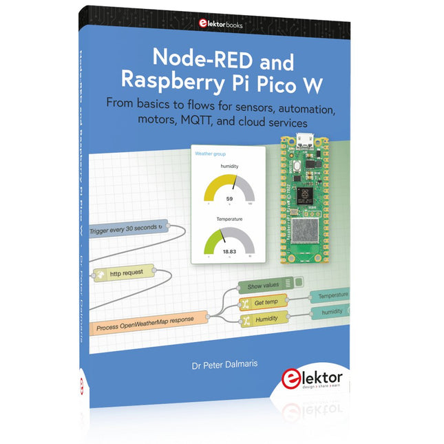
Elektor Publishing Node-RED and Raspberry Pi Pico W
From basics to flows for sensors, automation, motors, MQTT, and cloud services This book is a learning guide and a reference. Use it to learn Node-RED, Raspberry Pi Pico W, and MicroPython, and add these state-of-the-art tools to your technology toolkit. It will introduce you to virtual machines, Docker, and MySQL in support of IoT projects based on Node-RED and the Raspberry Pi Pico W. This book combines several elements into a platform that powers the development of modern Internet of Things applications. These elements are a flow-based server, a WiFi-enabled microcontroller, a high-level programming language, and a deployment technology. Combining these elements gives you the tools you need to create automation systems at any scale. From home automation to industrial automation, this book will help you get started. Node-RED is an open-source flow-based development tool that makes it easy to wire together devices, APIs, and online services. Drag and drop nodes to create a flowchart that turns on your lights at sunset or sends you an email when a sensor detects movement. Raspberry Pi Pico W is a version of the Raspberry Pi Pico with added 802.11n Wi-Fi capability. It is an ideal device for physical computing tasks and an excellent match to the Node-RED. Quick book facts Project-based learning approach. Assumes no prior knowledge of flow-based programming tools. Learn to use essential infrastructure tools in your projects, such as virtual machines, Docker, MySQL and useful web APIs such as Google Sheets and OpenWeatherMap. Dozens of mini-projects supported by photographs, wiring schematics, and source code. Get these from the book GitHub repository. Step-by-step instructions on everything. All experiments are based on the Raspberry Pi Pico W. A Wi-Fi network is required for all projects. Hardware (including the Raspberry Pi Pico W) is available as a kit. Downloads GitHub
€ 49,95
Mitglieder: € 44,96
-

Elektor Digital Nucleo Boards Programming with the STM32CubeIDE (E-book)
Hands-on in more than 50 projects STM32 Nucleo family of processors are manufactured by STMicroelectronics. These are low-cost ARM microcontroller development boards. This book is about developing projects using the popular STM32CubeIDE software with the Nucleo-L476RG development board. In the early Chapters of the book the architecture of the Nucleo family is briefly described. The book covers many projects using most features of the Nucleo-L476RG development board where the full software listings for the STM32CubeIDE are given for each project together with extensive descriptions. The projects range from simple flashing LEDs to more complex projects using modules, devices, and libraries such as GPIO, ADC, DAC, I²C, SPI, LCD, DMA, analogue inputs, power management, X-CUBE-MEMS1 library, DEBUGGING, and others. In addition, several projects are given using the popular Nucleo Expansion Boards. These Expansion Boards plug on top of the Nucleo development boards and provide sensors, relays, accelerometers, gyroscopes, Wi-Fi, and many others. Using an expansion board together with the X-CUBE-MEMS1 library simplifies the task of project development considerably. All the projects in the book have been tested and are working. The following sub-headings are given for each project: Project Title, Description, Aim, Block Diagram, Circuit Diagram, and Program Listing for the STM32CubeIDE. In this book you will learn about STM32 microcontroller architecture; the Nucleo-L476RG development board in projects using the STM32CubeIDE integrated software development tool; external and internal interrupts and DMA; DEBUG, a program developed using the STM32CubeIDE; the MCU in Sleep, Stop, and in Standby modes; Nucleo Expansion Boards with the Nucleo development boards. What you need a PC with Internet connection and a USB port; STM32CubeIDE software (available at STMicroelectronics website free of charge) the project source files, available from the book’s webpage hosted by Elektor; Nucleo-L476RG development board; simple electronic devices such as LEDs, temperature sensor, I²C and SPI chips, and a few more; Nucleo Expansion Boards (optional).
€ 39,95
Mitglieder: € 35,96
-
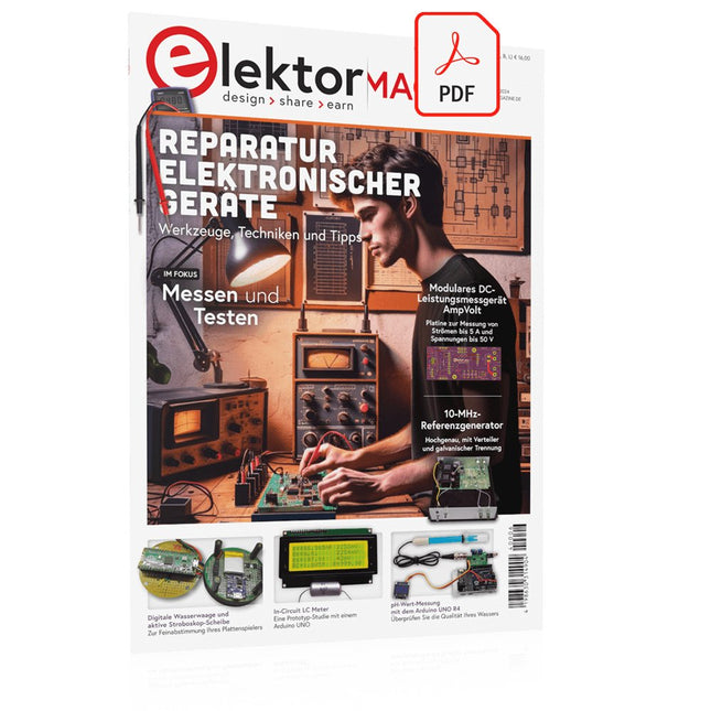
Elektor Digital Elektor 05-06/2024 (PDF)
Diese Ausgabe steht allen GOLD- und GREEN-Mitgliedern auf der ElektorMagazine-Website zum Download bereit! Sie sind noch kein Mitglied? Hier klicken! STM32 Wireless Innovation Design Contest – Die Gewinner stehen fest In-Circuit LC-MeterEine Prototyp-Studie Das modulare DC-Leistungsmessgerät AmpVoltTeil 1: Platine zur Messung von Strömen bis 5 A und Spannungen bis 50 V embedded world 2024 Reparatur von elektronischen GerätenWerkzeuge, Techniken und Tipps Aller Anfang ...muss nicht schwer sein: Wir setzen die Verstärkertheorie fort! Ein einfacher DDS-SignalgeneratorDirekte Digitale Synthese in ihrer reinsten Form Sparkplug im ÜberblickEine Spezifikation für MQTT-Daten Bemerkenswerte BauteileZeile für Zeile: CRTCs Radargesteuerte BeleuchtungAutomatisches Treppenhauslicht mit Anwesenheitsdetektion Digitale Wasserwaage und aktive Stroboskop-Scheibe für PlattenspielerFeinabstimmung Ihres Plattenspielers mit nur einem Gerät Open Source und seine Bedeutung für die Elektronikindustrie (2) M12-Rundsteckverbinder mit A-KodierungErste Wahl für industrielle Anwendungen Arduino-MesslaborEin 8-in-1-Test- und Messgerät für das heimische Elektroniklabor Soundkarte als Betrag/Phase-Impedanz-AnalysatorFür Frequenzen von 100 Hz bis 90 kHz pH-Wert-Messung mit dem Arduino UNO R4Überprüfen Sie die Qualität Ihres Wassers Aus dem Leben gegriffenStartrampe für Pangpong-Popöchen Digitales Speicheroszilloskop FNIRSI 1014DGute Leistung für knappe Budgets 2024: Eine Odyssee in die KIWie man die Objekterkennung zum Laufen bringt 10-MHz-ReferenzgeneratorHochgenau, mit Verteiler und galvanischer Trennung Projekt-Update #2: Energiemessgerät mit ESP32Einige Weiterentwicklungen Projekt 2.0Korrekturen, Updates und Leserbriefe Ein Interview mit Eben Upton, Geschäftsführer von Raspberry PiDer Raspberry Pi 5 und darüber hinaus
€ 11,90
-

Elektor Digital Elektor May/June 2023 (PDF)
Elektor GREEN and GOLD members can download their digital edition here. Not a member yet? Click here. Knowledge for All! Super Servo TesterTest Up to Four Servos Stand-Alone or In-System Analog Signals and MicrocontrollersADCs, DACs, Current Measurement, and More embedded world 2023 Sub-Nyquist Sampling in PracticeReliably Capturing Higher Frequencies Using Subsampling Android Smartphone Here, ESP32 There?Practical Pproject Using the Android Wi-Fi API Active 1-kHz Filter for Distortion MeasurementBetter Measurements Through Optimization of the Measurement Signal Starting Out in Electronics......Multivibrating Cheerfully Further! Err-lectronicsCorrections, Updates and Readers’ Letters The New I3C ProtocolA Worthy Successor to I²C, or Just More Hot Air? BlueRC: IR Remote Control with Smartphone and ESP32Adaptive and Universal Microcontroller Documentation Explained (Part 2)Registers and Block Diagrams Automating Test and MeasurementProgramming Test Equipment to Do What You Want Infographics: Test and Measurement Overvoltage Protection for Safe OperationTransient Protection for Non-Isolated DC/DC Power Modules Wiha Measuring EquipmentReliable Electrical Testers and Meters Automating Testing and Collaborating on Test Results From Life’s ExperienceHigh-Level Electronics Energy LoggerMeasuring and Recording Power Consumption Assembling the 4tronix M.A.R.S. Rover Kit Parking Disk with E-Paper DisplayAn Innovative Digital Replacement eCO₂ Telegram botAir-Quality Measurement with Telegram Notification Behind the Scenes of DIY High-End AudioElektor’s Ton Giesberts Interviewed on the Fine Art of Analog Design HomeLab ToursWork in Progress... RFID Tag Reading and RFID Door LockSample Projects from the Elektor Arduino Experimenting Bundle Oscilloscope Current Probe for RFRF Current Measurements Made Easy Not for the Faint-Hearted: Robot Arm KitWith Raspberry Pi Pico and MicroPython Generative AIWho Made This Anyway? Hexadoku
€ 7,50
-

Speciale Elektor / E&M: 33 Progetti Top di Elettronica
Una ricca selezione di articoli dal Mondo Elektor! Gli articoli di questo libro sono una selezione accurata, il "meglio del meglio" di circuiti e progetti recenti, realizzati da tecnici di grande talento provenienti da tutto il mondo. Nel tipico stile di Elektor, questa raccolta offre qualcosa di interessante per tutti, dai progettisti esperti a coloro che praticano l'elettronica nel tempo libero. Sommario Super Servo TesterProva Fino a Quattro Servocomandi, Stand-Alone o in Sistema The TubeUn Insolito Amplificatore a Valvole Cloc 2.0La Sveglia che Avete Sempre Desiderato Stazione Meteo LoRa Low-PowerCostruitevi una Stazione Meteorologica “Long Range” Uscita Video con Microcontrollori (Parte 1)Video Composito Uscita Video con Microcontrollori (Parte 2)Uscita VGA e DVI Un Raspberry Pi Pico come Analizzatore di SpettroFFT su Base Hardware a Basso Costo PIC O’Clock – In Contatto col TempoProgettare un Ricevitore di Segnali Orari SDR Frequenzimetro di Rete ACMisura Frequenza e Tensione della Rete Elettrica Generatore di Funzioni con Arduino NanoNano + Codice = Generatore di Funzioni Monitor CO2Un Approccio Fai-Da-Te per Il Controllo della Qualità dell‘Aria ChatMagLevLa Levitazione Magnetica con AI Alimentatore Lineare Variabile Combinato0…50 V / 0…2 A con Struttura Simmetrica Duale Ricevitore Digitale FM con Arduino e TEA5767Restate in Ascolto con un Arduino Nano Protezione Antigelo per Piante da FruttoCon Registrazione della Temperatura Carico Elettronico con Generatore di clock IntegratoPer Collaudare Alimentatori, Convertitori di Tensione e Batterie 128 Termostato Web con ESP32Mantieni il Vino alla Giusta Temperatura Iniezione di Segnali e di Potenza......per Rilevare le Interruzioni nei Cavi DIY LiPo Supercharger KitDal Prototipo al Mercato di Massa Livella Digitale con Stroboscopio AttivoCalibra il Tuo giradischi con Questo Strumento "Tutto-in-Uno" The Game of Life – 262.144 Modi di GiocareDal Progetto di un Lettore Rilevatore di PerditeCollegato ad Arduino Cloud Orologio di LissajousL’Incedere del Tempo con le Figure di Lissajous Mastermind – Controllato da ArduinoUna Versione Moderna del Classico Gioco di Decifrazione Generatore Audio Analogico 1 kHzOnda Sinusoidale a Bassa Distorsione Aggiorna il tuo Caricabatteria (Parte 1)Non Buttarlo, Modificalo! Aggiorna il tuo Caricabatteria (Parte 2)Non Buttarlo, Modificalo! Sistemi GNSS RTK a Basso CostoCon Accuratezza a Livello Centimetrico Esperimenti a 10 GHz con LNB Satellitari ModificatiSbloccare la Banda X a Basso Costo Telecamera per FerromodellismoInstalla un Modulo ESP32 CAM a Bordo! Monitor di Tensione con MicrocontrolloreProtezione dalla Scarica Profonda per Batterie e Altro Nodo Sensore AutonomoTrasmissione Dati LoRa con Alimentazione a Batterie Solari Layout e Sicurezza sul PCBConsigli per un Progetto Sicuro e Durevole
€ 29,95
Mitglieder: € 26,96
-
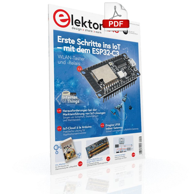
Elektor Digital Elektor 05-06/2022 (PDF)
Erste Schritte ins IoT - mit dem ESP32-C3 WLAN-Taster und -Relais IoT-Cloud à la Arduino Erster Kontakt mit der Arduino-Cloud Arduino-Shield für zwei Geiger-Müller-Zählrohre Ein hochempfindlicher, sehr stromsparender Strahlungsmesser CO2-Wächter Ein DIY-Ansatz zur Überwachung der Luftqualität MonkMakes: Luftqualitäts-Messgerätekit für den Raspberry Pi Misst Temperatur und CO2e Aller Anfang ... muss nicht schwer sein: Willkommen bei der Diode! Beherrschen Sie die Fachsprache? Fünf praktische Tipps für Ingenieure Tipps & Tricks beim Bauteiltest Recycling ohne teures Messeequipment Stromsparende Maulwurfscheuche Ein ATtiny13 ersetzt einen 555er Lichtschalter DeLux Eine Lösung für hochpräzises lichtgesteuertes Schalten Herausforderungen bei der Markteinführung von IoT-Lösungen Sorgen um Sicherheit, Skalierbarkeit und Wettbewerb Infografik 5-6/2022 Lieber doch verkabelt Tipps zur Entwicklung einer 1-GBit/s-Schnittstelle im Industrieumfeld Objekterkennung in Echtzeit für MCUs mit Edge Impulse FOMO Wanderfeldröhren Bemerkenswerte Bauteile NB-IoT - ein Überblick Standards, Abdeckung, Verträge und Module Dragino LPS8 Indoor-Gateway Schnell zum eigenen LoRaWAN-Gateway ATtiny-Mikrocontroller mit C und Assembler erforschen Beispiel-Kapitel: I/O-Ports des ATtiny Projekt 2.0 Korrekturen, Updates und Leserbriefe LoRa-GPS-Tracker - ein Update Daten abholen und visualisieren mit dem Raspberry Pi Schaltungssimulation mit TINA Design Suite und TINACloud Beispiel-Kapitel: Sinusförmige Oszillatoren WinUI 3: Neues Grafik-Framework für Windows-Apps Eine erste App für Elektroniker GUIs mit Python: Die schlechteste GUI der Welt Insel-Solaranlagen Elektrische Energie unabhängig vom Netz Das 10-Jahres-Handy Erneuern Sie Ihre Erwartungen! Hexadoku
€ 11,90
-

Elektor Labs Elektor Rauscharmes Labornetzteil
Das rauscharme Labornetzteil von Elektor ist ein vollständig analoges, einstellbares, symmetrisches Gerät mittlerer Leistung, das ohne Schalt- oder digitale Komponenten auskommt. Es bietet eine Ausgangsspannung, die zwischen 0 V und ±22 V einstellbar ist, sowie einen Ausgangsstrom, der von 0 A bis 1 A eingestellt werden kann. Da auf jegliche Art von Schalttechnik verzichtet wird, liefert das Design extrem geringes Rauschen. Zur Anzeige beider Ausgangsspannungen und -ströme werden vier kleine analoge Einbauinstrumente mit Drehspulmesswerk verwendet. Die meisten modernen Labornetzgeräte und AC-Adapter arbeiten mit Schaltnetzteiltechnik. Selbst die besten Ausführungen weisen zwangsläufig hochfrequente Restwelligkeit und andere Schaltartefakte am Ausgang auf, die die Prüfung empfindlicher analoger Schaltungen stören und Messungen kleiner Signale beeinträchtigen können. Um dieses Problem zu vermeiden, setzt dieses Konzept auf ein vollständig analoges Netzgerät. Obwohl es weniger effizient ist als vergleichbare Schaltnetzteile, spielt die geringere Effizienz beim Einsatz auf dem Prüfstand kaum eine Rolle und sorgt für sauberere und zuverlässigere Messergebnisse. Da viele analoge Schaltungen eine symmetrische Versorgung benötigen, liefert dieses Design positive und negative Ausgangsspannungen gleicher Höhe. Eine geringfügige Nachjustierung ist möglich, um eventuelle Ungleichgewichte auszugleichen. Selbstverständlich ist auch eine einstellbare Strombegrenzung integriert. Das Kit enthält die für den Aufbau des Netzteils erforderlichen Komponenten, mit Ausnahme der Transformatoren. Technische Daten Ausgangsspannung 0…+22 V, 0, −22 V Ausgangsstrom 0…+1 A, 0…−1 A Rauschen −85 dBV (bei 0,95 A/20 V, B = 22 kHz) −84 dBV (bei 0,95 A/20 V, B > 500 kHz) Restwelligkeit 50 µVRMS (bei 950 mA/20 V, B = 22 kHz, hauptsächlich 100-Hz-Anteil) Lieferumfang 3x Platinen: Regler (PCB-1), Netzfilter (PCB-2) und Transformator (PCB-3) Alle Bauteile mit Ausnahme der Netztransformatoren 4x Drehspulmesswerke Zusätzliche Teile für die Verdrahtung (Drähte, Bananenbuchsen, Kaltgeräte-Netzmodul usw.) Nicht enthalten Die drei Netztransformatoren Ein Gehäuse Stückliste Für die Spannungsregler-Platine (240386-1) Widerstände (250 mW, 1%) R1 = 12 Ω R2, R8, R37, R62 = 1 MΩ R3, R7, R10, R13, R17, R20, R22, R30, R35, R42, R45, R47, R55, R60 = 100 Ω, 600 mW R4, R5 = 4.7 kΩ R6 = 100 kΩ R9, R12, R14, R36, R38, R39, R61, R63, R66, R72, R78, R79 = 10.0 kΩ, 600 mW R11 = 9.76 kΩ, 600 mW R15, R40 = 44.2 kΩ, 600 mW R16, R41, R77 = 1 kΩ R18, R43 = 1.5 kΩ, 1 W, 5% R19, R44 = 470 Ω, 1 W, 5% R21, R46 = 330 Ω, 600 mW R23, R24, R48, R49 = 1.0 Ω, 1 W R25, R50 = 1 kΩ, 1 W, 5% R26, R28, R51, R53 = 1.000 kΩ 0.1%, 15 ppm/C R27, R29, R52, R54 = 10.00 kΩ 0.1%, 15 ppm/C R31, R56 = 1.2 kΩ, 1 W, 5% R32, R57 = 47 kΩ R33, R58 = 270 Ω R34, R59 = 27 kΩ R64, R69 = 12.0 kΩ R65 = 3.0 kΩ, 600 mW R67, R80 = 470 Ω, 600 mW R68, R70 = 6.8 kΩ, 600 mW R71 = 30.0 kΩ,, 600 mW R73, R74, R75, R76 = 10 MΩ P1, P2, P3 = 10 kΩ, 200 mW, 20%, potentiometer, 1 turns, single, lin., panel mount P4, P5 = 500 Ω, 500 mW, 10%, trimmer, 25 turns, 3296Y-1-501LF Bourns P6, P7 = 10 kΩ, 500 mW, 10%, trimmer, 25 turns, 3296Y-1-501LF Bourns Kondensatoren C1 = 100 nF, 50 V, 10%, ceramic X7R, LS 5 mm C2, C3, C6, C7, C30 = 10 µF, 63V, 20%, LS 2.5 mm, 3000hours@105°C C4, C5, C8, C9, C13, C14, C18, C19, C23, C24, C28, C29, C31, C32, C38, C39 = 100 nF, 250 V, 10%, PET, LS 7.5 mm C10, C20 = 47 nF, 100 V, 5%, PET, LS 5 mm C11, C21 = 10 nF, 100 V, 5%, PET, LS 5 mm C12, C22 = 220 µF, 35 V, 20%, 0.024 Ω, LS2.5/3.5 mm, Ir 3.4 A, 2000hours@125°C, polymer C15, C25 = 120 µF, 50 V, 20%, ESR 0.02 Ω, Diam. 10 mm max., LS 5 mm C16, C26 = 15 nF, 100 V, 5%, PET, LS 5 mm C17, C27 = 47 nF, 100 V, 5%, PET, LS 5 mm C33, C34 = 22 µF, 50 V, 20%, LS 2 mm, 10000 hours @ 105°C C35, C36, C44, C45 = 1 µF, 100 V, 10%, LS 5 mm, ceramic X7R C37 = 100 uF, 50 V, 20%. LS 3.5 mm C40, C41, C42, C43, C46, C47, C48, C49 = 1000 µF, 50 V, 20%, LS 5/7.5 mm, Ir 3.32 A, 10000hours@105°C, D 16 mm C50, C51, C52, C53 = 47 nF, 100 V, 10%, ceramic X7R, LS 5 mm Induktivitäten L1, L2 = 4.7 µH, 3.2 A, 0.033 Ω, LS 5 mm, RLB0914-4R7ML Bourns L3 = Commom mode choke, 14.5 mH, 3 A, SSRH24NH-30145 Kemet Halbleiter D1, D2, D3, D4, D5, D9, D10, D11, D15 = BAT85, DO-34 D6, D7, D12, D13 = SR560, DO-201AD D8, D14, D16 = 1N4148, DO-35 D17 = Zenerdiode, 5.6 V, 0.5 W, DO-41 D18, D19 = 1N4004, DO-41 D20, D21 D22, D23 = V30100CI-M3/P, dual common cathode, TO-220 D24 = Zener diode, 30 V, 1 W, DO-41 LED1, LED2 = LED, red, T-1 (3 mm) LED3, LED4 = LED, green, T-1 (3 mm) TVS1, TVS2 = BZW50-33B, R6 T1, T2, T4 = BC337.25, TO-92 T3 = NJW0302G, TO-3P T5, T6, T8 = BC327.25, TO-92 T7 = NJW0281G, TO-3P T9 = BD139, TO-126 (SOT-32) IC1 = LM334Z, TO-92 IC2 = LM4040AIZ-5.0/NOPB, TO-92 (TO-226AA-3) IC3, IC4 = OPA2992IDR, SOIC-8 IC5, IC6 = OPA4992IDR, SOIC-14 IC7 = OPA992IDBVR, SOT-23-5 IC8 = LM339N, DIP-14 IC9 = LM317, TO-220 IC10 = LM337, TO-220 Sonstiges F1, F2 = 5×20 mm fuse, 1.6 A, fast acting HS1, HS2 = Heatsink MC33271 (for T3/T7), 2.7°C/W, PCB mount, height 63.5 mm K1, K4 = 3-way screw terminal block, LS 3.5 mm, max. 1.5 mm² K2, K3 = 3-way screw terminal block, LS 3.5 mm, max. 1 mm² M1, M3 = Moving coil meter, Range 30 V, type 91C4, 45×45 mm M2, M4 = Moving coil meter, Range 1 A, type 91C4, 45×45 mm² RE1 = Relay DPDT,5V, UA2-5NU Verschiedenes 3× 3-way screw terminal block, LS 3.5 mm, max. 1 mm² (for P1, P2, P3) 4× Pin header, 1×2, vertical, pitch 2.54 mm (for LED1, LED2, LED3, LED4) 4× Pin socket, 1×2, vertical. pitch 2.54 mm (for LED1, LED2, LED3, LED4) 2× Heatsink FK222SA220, 20°C/W, PCB mount (for IC9 & IC10) 2× Mica thermal pad for TO-220, 12×18×0.05 mm (for IC9 & IC10) 2× Insulating bushing IB 6, TO-220 (for IC9 & IC10) 2× Ceramic thermal pad, 23×20×2 mm (for T3 & T7) 2× PCB Fuse Holder, for 5×20 mm fuse, 10 A (for F1, F2) 2× Cover for PCB Fuse Holder, transparent (for F1, F2) 2× 2-way screw terminal block, LS 3.5 mm, max. 1 mm² (for M1 & M3) 2× 2-way screw terminal block, LS 3.5 mm, max. 1.5 mm² (for M2 & M4) 8× M3 solder lug, thickness 0.35 mm (for M1…M4) M4 solder lug, thickness 0.35 mm (to connect 4 mm banana connectors) Screened cable, 1 pair, 2×24 AWG/0.22 mm², 1 m (for P1, P2 & P3) IC socket, DIP, 14 contacts (for IC8) M3 washer, plain, steel M3 screw, 16 mm, steel, pan head M3 nut M3 spring washer 50 mm M3 standoff, steel, male-female 12 mm M3 standoff, steel, male-female 10 mm M3 standoff, steel, male-female M3 screw, 8 mm, steel, pan head Für die Netzfilter-Platine (240386-2) Widerstand R1 = 220 kΩ, 1 W, 500 V, 5% Kondensatoren C1, C2 = 470 nF, 305 VAC, Class X2, 11 × 27 mm max., LS 15/22.5 mm C3, C4, C5, C6 = 2.2 nF, 300 VAC, Class Y2, 13 × 4 mm, LS 10 mm, PP Induktivitäten L1, L2 = Common-mode choke, 6.8 mH, 1.7 A, TDK B82732R2172B030 Halbleiter MOV1 = TVS varistor, 300 VAC, S14K300 (230 VAC, B72214S0301K101) and SK14K150 (150 VAC, B72214S0151K101) Sonstiges K1, K2 = 3-way screw terminal block, LS 7.62 mm F1 = Time-delay fuse, 0.5 A (230 VAC) or 1 A (115 VAC) Verschiedenes 1× Fuse holder, 5×20 mm, 10 A, 500 VAC 1× Transparent fuse cover 4× 10 mm M3 standoff, steel, male–female 4× M3 screw, 8 mm, steel, pan head 4× M3 nut Für die Transformator-Platine (240386-3) Widerstände R1, R2 = 2.7 kΩ, 600 mW, 1% R3 = 10.0 kΩ, 600 mW, 1% Kondensator C1 = 220 µF, 50 V, 20%, Ø10 mm, LS 5 mm, 4000 h @ 105°C Transformatoren (nicht im Lieferumfang dieses Kits enthalten!) TR1, TR2, TR3 = 2×7 V, 25 VA, PCB-mounted toroid, 70060K Talema Halbleiter D1–D4 = 1N4148, DO-35 D5, D6 = 1N4004, DO-41 D7 = Zener 5.6 V, 1.3 W, DO-41 LED1 = LED, red, T-1 (3 mm) IC1, IC2 = MOC8021M, CTR ≥ 1000%, DIP-6 Sonstiges F1, F2, F3 = 160 mA time-delay fuse (230 VAC) or 315 mA time-delay fuse (115 VAC) K1 = 2-way screw terminal block, LS 7.62 mm K2 = 3-way screw terminal block, LS 3.5 mm, max 1.5 mm² K3, K4 = 3-way screw terminal block, LS 3.5 mm, max 1 mm² RE1, RE2 = Relay DPDT, 5 A/250 VAC / 24 VDC Verschiedenes 1× Pin header 1×2, pitch 2.54 mm + matching socket for LED1 3× Fuse holder 5 × 20 mm, 10 A, 500 VAC + transparent cover 3× M4 screw, 8 mm, pan head + washer for TR1-TR3 8× M3 screw, 8 mm, pan head + nut + washer 8× 10 mm M3 standoff, steel, male–female 2× IC socket, DIP-6 for IC1 & IC2 Weitere Bauteile 1 m red insulated wire, stranded, 1.5 mm² 0.5 m blue insulated wire, stranded, 1.5 mm² 0.5 m black insulated wire, stranded, 1.5 mm², 0.5 m 2 m red insulated wire, stranded, D 0.56 mm (0.25 mm²) 2 m black insulated wire, stranded, D 0.56 mm (0.25 mm²) 0.5 m Multicore Cable, Flexible, 3 Core, 0.75 mm² (24 x 0.2 mm) Red banana socket Black banana socket Blue banana socket Green banana socket IEC Power Entry Module with switch, IEC C14 3 crimp terminals, FASTON, 4.75 x 0.81 mm 3 knobs Links Elektor Labs JumpStarter Page Artikel (Teil 1) Artikel (Teil 2)
€ 299,00€ 249,00Bestpreis
-
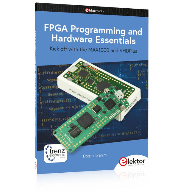
Elektor Publishing FPGA Programming and Hardware Essentials
Kick off with the MAX1000 and VHDPlus Ready to Master FPGA Programming? In this guide, we’re diving into the world of Field Programmable Gate Arrays (FPGAs) – a configurable integrated circuit that can be programmed after manufacturing. Imagine bringing your ideas to life, from simple projects to complete microcontroller systems! Meet the MAX1000: a compact and budget-friendly FPGA development board packed with features like memory, user LEDs, push-buttons, and flexible I/O ports. It’s the ideal starting point for anyone wanting to learn about FPGAs and Hardware Description Languages (HDLs). In this book, you’ll get hands-on with the VHDPlus programming language – a simpler version of VHDL. We’ll work on practical projects using the MAX1000, helping you gain the skills and confidence to unleash your creativity. Get ready for an exciting journey! You’ll explore a variety of projects that highlight the true power of FPGAs. Let’s turn your ideas into reality and embark on your FPGA adventure – your journey starts now! Exciting Projects You’ll Find in This Book Arduino-Driven BCD to 7-Segment Display Decoder Use an Arduino Uno R4 to supply BCD data to the decoder, counting from 0 to 9 with a one-second delay Multiplexed 4-Digit Event Counter Create an event counter that displays the total count on a 4-digit display, incrementing with each button press PWM Waveform with Fixed Duty Cycle Generate a PWM waveform at 1 kHz with a fixed duty cycle of 50% Ultrasonic Distance Measurement Measure distances using an ultrasonic sensor, displaying the results on a 4-digit 7-segment LED Electronic Lock Build a simple electronic lock using combinational logic gates with push buttons and an LED output Temperature Sensor Monitor ambient temperature with a TMP36 sensor and display the readings on a 7-segment LED Downloads Software
€ 39,95
Mitglieder: € 35,96
-

Elektor Digital SDR Hands-on Book (E-book)
The short-wave technique has a very particular appeal: It can easily bridge long distances. By reflecting short-wave signals off the conductive layers of the ionosphere, they can be received in places beyond the horizon and therefore can reach anywhere on earth. Although technology is striving for ever higher frequencies, and radio is usually listened to on FM, DAB+, satellite or the Internet, modern means of transmission require extensive infrastructure and are extremely vulnerable. In the event of a global power outage, there is nothing more important than the short-wave. Amateur radio is not only a hobby, it’s also an emergency radio system! Elektor’s SDR-Shield is a versatile shortwave receiver up to 30 MHz. Using an Arduino and the appropriate software, radio stations, morse signals, SSB stations, and digital signals can be received. In this book, successful author and enthusiastic radio amateur, Burkhard Kainka describes the modern practice of software defined radio using the Elektor SDR Shield. He not only imparts a theoretical background but also explains numerous open source software tools.
€ 29,95
Mitglieder: € 26,96
-

Elektor Publishing Oszilloskope
Verstehen und effektiv einsetzen Was in der Elektronik geschieht, ist mit bloßem Auge unsichtbar. Das Instrument, mit dem sich elektrische Signale präzise visualisieren lassen und die Effekte der Elektronik für uns sichtbar werden, ist das Oszilloskop. Leider wagt man sich beim Einstieg in die Elektronik oft ohne Oszilloskop vor. Man tappt dann im Dunkeln, sowohl praktisch als auch gedanklich. Die erste Beobachtung eines elektrischen Signals auf einem Bildschirm ist eine Offenbarung. Niemand möchte dieses Erlebnis danach noch einmal missen. Es gibt kein Zurück mehr. Wer in der Elektronik mit Freude und Verständnis vorankommen möchte, braucht unbedingt ein Oszilloskop. Dann stellt sich zunächst die Frage: Wie wählt man das richtige Oszilloskop aus? Und kaum ist diese Frage beantwortet, tauchen bereits die nächsten auf, die sich letztlich auf eine zentrale Frage reduzieren lassen: Wie nutzt man das Oszilloskop so, dass die Anzeige die Realität der Signale korrekt widerspiegelt? Rémy Mallard ist ein leidenschaftlicher Vermittler komplexer technischer Themen mit dem Talent, diese verständlich und fesselnd zu präsentieren. In diesem Buch beantwortet er wichtige Fragen zur Verwendung eines Oszilloskops und bietet zahlreiche Anleitungen, um die elektrischen Signale elektronischer Systeme zu erforschen und zu verstehen. Dank seines verständlichen Stils und seiner praktischen Einblicke ist dieses Buch ein wertvolles Werkzeug für alle, die ihr Elektronikwissen vertiefen möchten.
€ 44,80
Bestpreis
-

Elektor Publishing Tube Amplifier Circuits
From SRPP and Mu-Follower to OTL Designs Tube amplifiers suffer from distortion. Fortunately, circuits such as the SRPP amplifier, mu-follower, and beta-follower produce minimal distortion even at output voltages of 50 to 100 Vpeak. These designs are often published with errors. Without a sound understanding of the theory, it is easy to arrive at a flawed design. In the first section of this book, we investigate the origin of distortion, while in the second we investigate the design of and SRPP and a mu-follower. On the internet we can find the most exotic designs. Evaluating them teaches us that these designs often make matters worse rather than better. In the chapter on incorrect SRPPs and mu-followers, we sometimes see bizarre and misguided designs where using a simple single-triode amplifier would perform much better. Push-pull output stages also exist. A great number of them are examined, and their similarity to the SRPP is discussed. This is done especially with the help of the theory behind the OTL based on the ‘mother’ of all OTLs, the Philips HF303. Finally, attention is given to frequency characteristics and technical matters such as the supply voltage and the filament power supply. To illustrate these points, there are a few designs covering the subjects discussed. This book presents much new theory that has not been published before. It is often an eye-opener, showing that many things have a beautiful and unexpected simplicity.
€ 44,95
Mitglieder: € 40,46
-

Elektor Digital Raspberry Pi (überarbeitete und erweiterte Neuauflage | PDF)
Raspberry Pi (Neuauflage) | E-Buch
€ 34,80
Mitglieder: € 31,32


