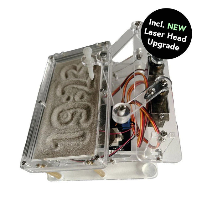
Dieses Bundle enthält die beliebte Elektor Sanduhr für Raspberry Pi Pico und das neue Elektor Laserkopf-Upgrade und bietet damit noch mehr Möglichkeiten zur Zeitanzeige. Sie können die aktuelle Uhrzeit nicht nur in Sand "gravieren", sondern sie jetzt auch alternativ auf eine im Dunkeln leuchtende Folie schreiben oder grüne Zeichnungen erstellen.
Inhalt des Bundles
Elektor Sanduhr für Raspberry Pi Pico (Einzelpreis: 50 €)
Elektor Laserkopf-Upgrade für Sanduhr (Einzelpreis: 35 €)
Elektor Sanduhr für Raspberry Pi Pico (Raspberry Pi-basierter Eyecatcher)
Eine handelsübliche Sanduhr zeigt nur, wie die Zeit verrinnt. Dagegen zeigt diese Raspberry Pi Pico-gesteuerte Sanduhr die genaue Uhrzeit an, indem die vier Ziffern für Stunde und Minute in die Sandschicht "eingraviert" werden. Nach einer einstellbaren Verzögerung wird der Sand durch zwei Vibrationsmotoren flachgedrückt und der Zyklus beginnt von vorne.
Das Herzstück der Sanduhr sind zwei Servomotoren, die über einen Pantographenmechanismus einen Schreibstift antreiben. Ein dritter Servomotor hebt den Stift auf und ab. Der Sandbehälter ist mit zwei Vibrationsmotoren ausgestattet, um den Sand zu glätten. Der elektronische Teil der Sanduhr besteht aus einem Raspberry Pi Pico und einer RTC/Treiberplatine mit Echtzeituhr, plus Treiberschaltungen für die Servomotoren.
Eine ausführliche Bauanleitung steht zum Download bereit.
Features
Abmessungen: 135 x 110 x 80 mm
Bauzeit: ca. 1,5 bis 2 Stunden
Lieferumfang
3x vorgeschnittene Acrylplatten mit allen mechanischen Teilen
3x Mini-Servomotoren
2x Vibrationsmotoren
1x Raspberry Pi Pico
1x RTC/Treiberplatine mit montierten Teilen
Muttern, Bolzen, Abstandshalter und Drähte für die Baugruppe
Feinkörniger weißer Sand
Elektor Laserkopf-Upgrade für Sanduhr
Der neue Elektor-Laserkopf verwandelt die Elektor Sanduhr in eine Uhr, die die Zeit auf eine im Dunkeln leuchtende Folie statt auf Sand schreibt. Neben der Anzeige der Zeit können damit auch flüchtige Zeichnungen erstellt werden. Der 5-mW-Laserpointer mit einer Wellenlänge von 405 nm erzeugt leuchtend grüne Zeichnungen auf der im Dunkeln leuchtenden Folie. Um optimale Ergebnisse zu erzielen, verwenden Sie das Kit in einem schwach beleuchteten Raum. Achtung: Schauen Sie niemals direkt in den Laserstrahl!
Der Bausatz enthält alle notwendigen Komponenten, es ist jedoch das Anlöten von drei Drähten erforderlich.
Hinweis: Dieses Kit ist auch mit der originalen Arduino-basierten Sanduhr aus dem Jahr 2017 kompatibel. Weitere Einzelheiten finden Sie unter Elektor 1-2/2017 und Elektor 1-2/2018.
Program and build Arduino-based ham station utilities, tools, and instruments
In addition to a detailed introduction to the exciting world of the Arduino microcontroller and its many variants, this book introduces you to the shields, modules, and components you can connect to the Arduino. Many of these components are discussed in detail and used in the projects included in this book to help you understand how these components can be incorporated into your own Arduino projects. Emphasis has been placed on designing and creating a wide range of amateur radio-related projects that can easily be built in just a few days.
This book is written for ham radio operators and Arduino enthusiasts of all skill levels, and includes discussions about the tools, construction methods, and troubleshooting techniques used in creating amateur radio-related Arduino projects. The book teaches you how to create feature-rich Arduino-based projects, with the goal of helping you to advance beyond this book, and design and build your own ham radio Arduino projects.
In addition, this book describes in detail the design, construction, programming, and operation of the following projects:
CW Beacon and Foxhunt Keyer
Mini Weather Station
RF Probe with LED Bar Graph
DTMF Tone Encoder
DTMF Tone Decoder
Waveform Generator
Auto Power On/Off
Bluetooth CW Keyer
Station Power Monitor
AC Current Monitor
This book assumes a basic knowledge of electronics and circuit construction. Basic knowledge of how to program the Arduino using its IDE will also be beneficial.
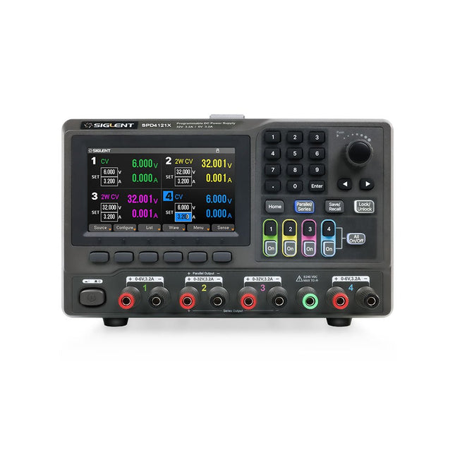
The Siglent SPD4121X is a 4-channel DC Linear Programmable Power Supply equipped with a 4.3-inch TFT-LCD display, friendly human-machine interface, and excellent performance indicators. Real-time waveform display provides engineers with an informative user interface.
SPD4121X offers a total output power of 285 W with a resolution of 1 mV/1 mA. The maximum voltage and current for each channel are as follows:
CH1: 15 V/1.5 A
CH2: 12 V/10 A
CH3: 12 V/10 A
CH4: 15 V/1.5 A
Features
Rated output power: 285 W
Rated voltage: 32 V, 12 V, 30 V
Up to four high-precision power supplies with independent controllable outputs, supporting CH2 and CH3 series and parallel connections
Clear graphical interface with waveform and timer display modes
5-digit voltage and current display with minimum resolution of 1 mV, 1 mA
Fast output response time: <50us
The high current channel support remote voltage compensation sense function. The maximum compensation voltage is 0.6 V
Overvoltage protection and overcurrent protection or safe and accurate operation
Equipped with a 4.3-inch TFT-LCD display (480 x 272 resolution)
USB and LAN standard communication
USB-GPIB module is optional
Excellent channel density with up to 4 channels in a 3U half rack package
Internal data storage for setups and parameters
Embedded Web Server with instrument communication that doesn’t require software installation
Fully SCPI programming command set support as well as a LabView driver for remote control and system automation
Technische Daten
SPD4323X
SPD4121X
SPD4306X
Channel Output
CH1: Voltage 0 to 6 V Current 0 to 3.2 ACH2: Voltage 0 to 32 V Current 0 to 3.2 ACH3: Voltage 0 to 32 V Current 0 to 3.2 ACH4: Voltage 0 to 6 V Current 0 to 3.2 A
CH1: Voltage 0 to 15 V Current 0 to 1.5 ACH2: Voltage 0 to 12 V Current 0 to 10 ACH3: Voltage 0 to 12 V Current 0 to 10 ACH4: Voltage 0 to 15 V Current 0 to 1.5 A
CH1: Voltage 0 to 15 V Current 0 to 1.5 ACH2: Voltage 0 to 30 V Current 0 to 6 ACH3: Voltage 0 to 30 V Current 0 to 6 ACH4: Voltage 0 to 15 V Current 0 to 1 A
Resolution
1 mV, 1 mA
1 mV, 1 mA
1 mV, 1 mA
Setting Accuracy
Voltage: ±(0.03% of reading+10) mV, Current: ±(0.3% of reading+10) mA
Voltage: ±(0.03% of reading+10) mV, Current: ±(0.3% of reading+10) mA
Voltage: ±(0.03% of reading+10) mV, Current: ±(0.3% of reading+10) mA
Readback Accuracy
Voltage: ±(0.03% of reading+10) mV, Current: ±(0.3% of reading+10) mA
Voltage: ±(0.03% of reading+10) mV, Current: ±(0.3% of reading+10) mA
Voltage: ±(0.03% of reading+10) mV, Current: ±(0.3% of reading+10) mA
Display
4.3" TFT-LCD 5-digit voltage and current display
4.3" TFT-LCD 5-digit voltage and current display
4.3" TFT-LCD 5-digit voltage and current display
Output power
240 W
285 W
400 W
Lieferumfang
1x Siglent SPD4121X Power Supply
1x Power cord (EU)
1x Output test cord (3 A)
1x USB cable
1x Quick start guide
Downloads
Datasheet
Manual
Quick start
Dit boek bevat 50 leuke en spannende projecten met PIC microcontrollers zoals een laser alarm, USB plaagmuis, eierwekker, jongerenverjager, geluidsschakelaar, capacitieve vloeistofniveau meting, 'vinger in het water' sensor, bewaking van een ruimte met een camera, 220 volt lichtdimmer, pratende microcontroller en nog veel meer. Er komen talloze technieken aan de orde zoals relais, wisselstroomregeling (ook 220 volt), I2C, SPI, RS232, USB, puls breedte modulatie, rotary encoder, interrupts, infrarood, analoog-digitaal conversie (en andersom), 7-segment display en zelfs CAN bus.
U kunt dit boek gebruiken om de verschillende projecten na te bouwen en daarna in de praktijk te brengen. Door de duidelijke uitleg, schema's en zelfs foto's van de opstelling is het nabouwen een leuke bezigheid. Bij ieder project wordt uitgelegd waarom het juist op die manier is uitgevoerd, en wordt kort de theorie behandeld. U kunt dit boek dus gebruiken als studieboek, of als basis voor grotere en ingewikkeldere projecten. Alle schakelingen zijn op een steekbord uitgevoerd zodat uitbreiden en aanpassen gemakkelijk is.
De drie PIC microcontrollers die in dit boek gebruikt worden, zijn de 16f877A, 18f4455 en 18f4685. Daarnaast komt aan de orde hoe u de programma's van de ene naar de andere microcontroller kunt overzetten (er worden 15 types ondersteund) inclusief twee praktijkvoorbeelden.
Alle benodigde software kunt u gratis downloaden. Dat geldt ook voor de open source programmeertaal JAL. Deze krachtige maar toch eenvoudig te leren taal wordt zowel door hobbyisten als professionals gebruikt.
Dit boek is ook goed te gebruiken als naslagwerk. U kunt er de uitleg van alle opdrachten van de programmeertaal JAL in terugvinden, en tevens van de gebruikte uitbreidingsbibliotheken. Via de index vindt u gemakkelijk projecten die als voorbeeld kunnen dienen voor de belangrijkste JAL opdrachten. Zelfs wanneer u alle projecten een keer gemaakt hebt, zal dit boek nog lang een plekje naast uw PC behouden.
The tinySA Ultra+ ZS-407 is a compact, handheld spectrum analyzer and signal generator. Covering 100 kHz to 7.3 GHz in Ultra mode, it lets you visualize and analyze RF signals from HF right through many modern wireless bands – and can even spot signals up to ~12 GHz thanks to harmonic tracking.
The intuitive 4-inch resistive touchscreen and rechargeable battery make it great for fieldwork, while features like a built-in signal generator, switchable bandpass filters, step attenuator, USB-PC control and auto-calibration add serious versatility.
Features
Screen size: 4 inch (480 x 320)
Spectrum Analyzer for 0.1-900 MHz or, with Ultra mode enabled up to 7.3 GHz, level calibrated up to 7.3 GHz. Can observe signals up to 12 GHz
Signal Generator with sine wave output between 0.1-900 MHz or square wave up to 6.3 GHz or RF test signal output up to 7.3 GHz when not used as Spectrum Analyzer.
Switchable resolution bandpass filters from 200 Hz to 850 kHz
Built-in 20 dB optional LNA
Color display showing max 450 points providing gapless covering up to the full frequency range.
MicroSD card slot for storing measurements, settings and screen captures.
Technische Daten (Spektrum-Analyzer)
Input frequency range from 100 kHz to 900 MHz in normal mode and up to 7.3 GHz with ULTRA mode enabled
Input impedance 50 ohm when input attenuation set to 10 dB or more.
Selectable manual and automatic input attenuation between 0 dB and 31 dB in 1 dB steps when LNA not active
Maximum +/-5V DC input
Absolute maximum input level of +6 dBm with 0 dB internal attenuation
Absolute maximum short term peak input power of +20 dBm with 30 dB internal attenuation
Suggested maximum input power of +0 dBm with internal attenuation in automatic mode
For best measurements keep input power below -25 dBm
Input Intercept Point of third order modulation products (IIP3) of +15 dBm with 0 dB internal attenuation
1 dB compression point at -1 dBm with 0 dB internal attenuation
Power detector resolution of 0.5 dB and linearity versus frequency of ±2 dB below 5.3 GHz, ±5dB between 5.3 GHz and 6 GHz
Minimum burst length for correct level measurement at 850 kHz RBW in zero span mode of 50 microseconds
Absolute power level accuracy after power level calibration of ±2 dB
Built-in optional 20 dB LNA with Noise Figure of 5 dB up to 6 GHz
Lowest discernible signal without LNA at 30 MHz using a resolution bandwidth of 30 kHz of -102 dBm
Lowest discernible signal with LNA at 30 MHz using a resolution bandwidth of 200 Hz of -145 dBm
Frequency accuracy equal to the selected resolution bandwidth
Phase noise at 30 MHz of -108 dB/Hz at 100 kHz offset and -115 dB/Hz at 1MHz offset
Spur free dynamic range when using a 30 kHz resolution bandwidth of 70 dB
Resolution filters with a width of 0.2, 1, 3, 10, 30, 100, 300, 600 and 850 kHz
On screen resolution of 51, 101, 145, 290 or 450 measurement points.
Scanning speed of over 1000 points/second using largest resolution filters.
Automatic optimization of actual scanning points to ensure coverage of the whole scan range regardless of the chosen resolution bandwidth
Spur suppression option for assessing if certain signals are internally generated or actually present in the input signal
Headphone output for listening to the demodulated audio (AM only). Stereo connector with or without microphone, high impedance is louder, short protected
Technische Daten (Signalgenerator)
Sine wave output with harmonics below -40 dB of fundamental from 100 kHz to 900 MHz
Output level selectable in 1 dB steps between -115 dBm and -19 dBm
Above 800 MHz choice of two output modes:
Cleanest signal mode: square wave, up to 6 GHz with coarse frequency steps and less accurate output level
Highest accuracy mode: reduced harmonics with possibly strong spurs up to 7.3 GHz with frequency resolution equal to below 800 MHz and fine output level steps
Level accuracy ±2 dB up to 800 MHz between -72 dBm and -19 dBm, less accuracy below -72 dBm, even less accuracy below -110 dBm
Output frequency resolution 57.2 Hz
Optional AM or FM modulation frequencies between 50 Hz and 5 kHz (AM) or 1 kHz (FM) or sweep over selectable frequency span
AM modulation depth between 10% and 100%
FM deviation between 1 kHz and 300 kHz
Optional output level sweep over maximum the entire output level range
Lieferumfang
1x tinySA Ultra+ ZS407 Spectrum Analyzer
2x SMA connection cables
1x Barrel connector
1x Antenna with SMA connector
1x USB-C cable
1x microSD card (32 GB)
Downloads
Wiki
A Practical Guide to Tube Electronics
Vacuum tubes continue to exert a special fascination. Their long-lasting operation, robustness, and characteristic behavior fundamentally distinguish them from modern semiconductor technology. Despite their age, tubes are by no means merely historical components; they are still used today in audio technology, measurement technology, and especially in hobbyist applications.
This book is aimed at electronics enthusiasts and hobbyists who want to not only learn about and understand vacuum tubes in theory, but also use them in practice. It conveys the fundamentals of tube technology, explains the different designs and designations, shows typical circuits, and addresses power supplies, measurements, and safety-related aspects. The focus is on practical explanations and realistic examples from the workshop. Numerous tips help you avoid typical mistakes, build circuits, and understand tube devices and their construction. Basic knowledge of electronics is assumed.
Vacuum Tubes: A Practical Guide to Tube Electronics offers an accessible and thorough introduction to tube technology – factual, comprehensible, and with a clear focus on practical applications.
An Introduction to Circuit Simulation
LTspice, developed by Analog Devices, is a powerful, fast, and free SPICE simulator, schematic capture, and waveform viewer with a large database of components supported by SPICE models from all over the world. Drawing a schematic in LTspice is easy and fast. Thanks to its powerful graphing features, you can visualize the voltages and currents in a circuit, and also the power consumption of its components and much more.
This book is about learning to design and simulate electronic circuits using LTspice. Among others, the following topics are treated:
DC and AC circuits
Signal diodes and Zener diodes
Transistor circuits including oscillators
Thyristor/SCR, diac, and triac circuits
Operational amplifier circuits including oscillators
The 555 timer IC
Filters
Voltage regulators
Optocouplers
Waveform generation
Digital logic simulation including the 74HC family
SPICE modeling LTspice is a powerful electronic circuit simulation tool with many features and possibilities. Covering them all in detail is not possible in a book of this size. Therefore, this book presents the most common topics like DC and AC circuit analysis, parameter sweeping, transfer functions, oscillators, graphing, etc. Although this book is an introduction to LTspice, it covers most topics of interest to people engaged in electronic circuit simulation.
The book is aimed at electronic/electrical engineers, students, teachers, and hobbyists. Many tested simulation examples are given in the book. Readers do not need to have any computer programming skills, but it will help if they are familiar with basic electronic circuit design and operation principles. Readers who want to dive deeper can find many detailed tutorials, articles, videos, design files, and SPICE circuit models on the Internet.
All the simulation examples used in the book are available as files at the webpage of this book. Readers can use these example circuits for learning or modify them for their own applications.
Over 45 Builds for the Legendary 555 Chip (and the 556, 558)
The 555 timer IC, originally introduced by the Signetics Corporation around 1971, is sure to rank high among the most popular analog integrated circuits ever produced. Originally called the IC Time Machine, this chip has been used in many timer-related projects by countless people over decades.
This book is all about designing projects based on the 555 timer IC. Over 45 fully tested and documented projects are presented. All projects have been fully tested by the author by constructing them individually on a breadboard. You are not expected to have any programming experiences for constructing or using the projects given in the book. However, it’s definitely useful to have some knowledge of basic electronics and the use of a breadboard for constructing and testing electronic circuits.
Some of the projects in the book are:
Alternately Flashing Two LEDs
Changing LED Flashing Rate
Touch Sensor On/Off Switch
Switch On/Off Delay
Light-Dependent Sound
Dark/Light Switch
Tone Burst Generator
Long Duration Timer
Chasing LEDs
LED Roulette Game
Traffic Lights
Continuity Tester
Electronic Lock
Switch Contact Debouncing
Toy Electronic Organ
Multiple Sensor Alarm System
Metronome
Voltage Multipliers
Electronic Dice
7-Segment Display Counter
Motor Control
7-Segment Display Dice
Electronic Siren
Various Other Projects
The projects given in the book can be modified or expanded by you for your very own applications. Electronic engineering students, people engaged in designing small electronic circuits, and electronic hobbyists should find the projects in the book instructive, fun, interesting, and useful.
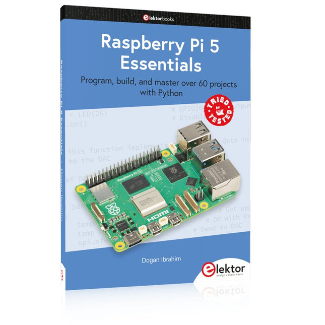
Program, build, and master over 60 projects with Python
The Raspberry Pi 5 is the latest single-board computer from the Raspberry Pi Foundation. It can be used in many applications, such as in audio and video media centers, as a desktop computer, in industrial controllers, robotics, and in many domestic and commercial applications. In addition to the well-established features found in other Raspberry Pi computers, the Raspberry Pi 5 offers Wi-Fi and Bluetooth (classic and BLE), which makes it a perfect match for IoT as well as in remote and Internet-based control and monitoring applications. It is now possible to develop many real-time projects such as audio digital signal processing, real-time digital filtering, real-time digital control and monitoring, and many other real-time operations using this tiny powerhouse.
The book starts with an introduction to the Raspberry Pi 5 computer and covers the important topics of accessing the computer locally and remotely. Use of the console language commands as well as accessing and using the desktop GUI are described with working examples. The remaining parts of the book cover many Raspberry Pi 5-based hardware projects using components and devices such as
LEDs and buzzers
LCDs
Ultrasonic sensors
Temperature and atmospheric pressure sensors
The Sense HAT
Camera modules
Example projects are given using Wi-Fi and Bluetooth modules to send and receive data from smartphones and PCs, and sending real-time temperature and atmospheric pressure data to the cloud.
All projects given in the book have been fully tested for correct operation. Only basic programming and electronics experience are required to follow the projects. Brief descriptions, block diagrams, detailed circuit diagrams, and full Python program listings are given for all projects described.
Clever Tricks with ATmega328 Pro Mini Boards
With a simple Pro Mini board and a few other components, projects that 20 or 30 years ago were unthinkable (or would have cost a small fortune) are realized easily and affordably in this book: From simple LED effects to a full battery charging and testing station that will put a rechargeable through its paces, there’s something for everyone.
All the projects are based on the ATmega328 microcontroller, which offers endless measuring, switching, and control options with its 20 input and output lines. For example, with a 7-segment display and a few resistors, you can build a voltmeter or an NTC-based thermometer. The Arduino platform offers the perfect development environment for programming this range of boards.
Besides these very practical projects, the book also provides the necessary knowledge for you to create projects based on your own ideas. How to measure, and what? Which transistor is suitable for switching a certain load? When is it better to use an IC? How do you switch mains voltage? Even LilyPad-based battery-operated projects are discussed in detail, as well as many different motors, from simple DC motors to stepper motors.
Sensors are another exciting topic: For example, a simple infrared receiver that can give disused remote controls a new lease on life controlling your home, and a tiny component that can actually measure the difference in air pressure between floor and table height!
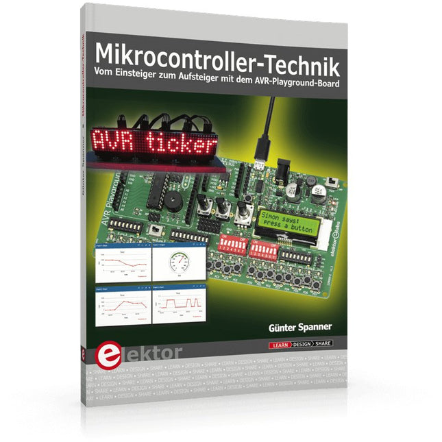
Mikrocontroller haben sich in den letzten Jahren in praktisch allen Bereichen der modernen Technik etabliert. In zunehmendem Maße dringen sie auch in die Gebiete der Künstlichen Intelligenz und der Robotertechnik vor. Das vorliegende Buch gibt eine umfassende Einführung in die Welt der Controller-Technik mit all ihren Facetten, von der einfachen Steuerung über die Sensor-Technik bis hin zur Datenübertragung in das Internet.
Als Basis dafür dient das von Elektor entwickelte AVR-Playground-Board. Das Board kann mit Controllern der ATmega-Familie bestückt werden und ist mit dem bekannten Arduino-System kompatibel, so dass auch die verschiedenen Arduino-Hardware-Erweiterungen verwendet werden können.
Für die Programmierung kommt die Sprache „C“ zum Einsatz. Auch hier wird im Buch auf das Arduino-System zurückgegriffen. Die frei verfügbare Arduino-Entwicklungsumgebung erlaubt den leichten Einstieg, ohne dass später Einschränkungen in Kauf genommen werden müssen. Die Hardware-nahe Programmierung steht dabei besonders im Fokus. Nach der Erläuterung von grundlegenden Anwendungen wird auf die anspruchsvolleren Themen wie Interrupts, Timer und Counter, Pulsweitenmodulation und Analog-Digital-Wandlung eingegangen.
Praktische Anwendungen können sowohl mit einem Arduino als auch mit dem AVR-Playground-Board durchgeführt werden. Da das AVR-Playground-Board bereits über eine Vielzahl von Peripherie-Einheiten verfügt, sind nur noch wenige externe Bauteile erforderlich. Das Board kann im Elektor-Shop hier bezogen werden.