
Suchergebnisse für "linear OR circuit OR design OR handbook"
-

Elektor Classics The Ton Giesberts Collection (USB-Stick)
Praxisprojekte aus Analogtechnik, Audiotechnik und darüber hinaus Entdecken Sie eine bemerkenswerte Sammlung mit mehr als 250 Elektronikprojekten, die im Elektor Magazin veröffentlicht und vom renommierten Elektor-Laboringenieur Ton Giesberts sorgfältig ausgewählt wurden. Der USB-Stick vereint eine große Vielfalt an Schaltungen, Entwicklungen und praxisnahen Projektideen, die im Laufe der Jahre von zahlreichen Elektor-Autoren und Ingenieuren erstellt wurden. Das umfangreiche Archiv deckt ein breites Spektrum an Elektronikthemen ab und ist eine wertvolle Wissens- und Inspirationsquelle für Ingenieure, Maker, Studierende und Elektronikbegeisterte. Mehr als 250 ausgewählte Elektor-Projekte Sorgfältig zusammengestellt von Elektor-Ingenieur Ton Giesberts Ideal zum Nachbauen, Experimentieren und Entdecken neuer Ideen Entdecken Sie Jahrzehnte geballter Elektor-Kompetenz in einer umfassenden Projektsammlung. Highlights Q-Watt Audio-Endstufe Fortissimo-100 High-End-Verstärker Pufferplatine für den Raspberry Pi 400 USB-zu-Multiprotokoll-Seriell-Wandler DDS-Funktionsgenerator AC/DC-Leistungsmesser Charge-a-Phone Technische Daten Speicher 8 GB Anschlüsse 1x USB-A1x USB-C Systemvoraussetzungen Rechner geeignet für Adobe Reader ab Version 7.0 Web-Browser
€ 49,95
Mitglieder: € 44,96
-

Elektor Digital Raspberry Pi 3 – Basic to Advanced Projects (E-book)
This book is about the Raspberry Pi 3 computer and its use in various control and monitoring applications. The book explains in simple terms and with tested and working example projects, how to configure the Raspberry Pi 3 computer, how to install and use the Linux operating system, and how to write hardware based applications programs using the Python programming language. The nice feature of this book is that it covers many Raspberry Pi 3 based hardware projects using the latest hardware modules such as the Sense HAT, Swiss Pi, MotoPi, Camera module, and many other state of the art analog and digital sensors. An important feature of the Raspberry Pi 3 is that it contains on-board Bluetooth and Wi-Fi modules. Example projects are given in the book on using the Wi-Fi and the Bluetooth modules to show how real-data can be sent to the Cloud using the Wi-Fi module, and also how to communicate with an Android based mobile phone using the Bluetooth module. The book is ideal for self-study, and is intended for electronic/electrical engineering students, practising engineers, research students, and for hobbyists. It is recommended that the book should be followed in the given Chapter order. Over 30 projects are given in the book. All the projects in the book are based on the Python programming language and they have been fully tested. Full program listings of every project are given in the book with comments and full descriptions. Experienced programmers should find it easy to modify and update the programs to suit their needs. The following sub-headings are given for each project to make it as easy as possible for the readers to follow the projects: Project title Description Aim of the project Raspberry Pi type Block diagram Circuit diagram Program listing
€ 29,95
Mitglieder: € 26,96
-

Elektor Labs Elektor Rauscharmes Labornetzteil
Das rauscharme Labornetzteil von Elektor ist ein vollständig analoges, einstellbares, symmetrisches Gerät mittlerer Leistung, das ohne Schalt- oder digitale Komponenten auskommt. Es bietet eine Ausgangsspannung, die zwischen 0 V und ±22 V einstellbar ist, sowie einen Ausgangsstrom, der von 0 A bis 1 A eingestellt werden kann. Da auf jegliche Art von Schalttechnik verzichtet wird, liefert das Design extrem geringes Rauschen. Zur Anzeige beider Ausgangsspannungen und -ströme werden vier kleine analoge Einbauinstrumente mit Drehspulmesswerk verwendet. Die meisten modernen Labornetzgeräte und AC-Adapter arbeiten mit Schaltnetzteiltechnik. Selbst die besten Ausführungen weisen zwangsläufig hochfrequente Restwelligkeit und andere Schaltartefakte am Ausgang auf, die die Prüfung empfindlicher analoger Schaltungen stören und Messungen kleiner Signale beeinträchtigen können. Um dieses Problem zu vermeiden, setzt dieses Konzept auf ein vollständig analoges Netzgerät. Obwohl es weniger effizient ist als vergleichbare Schaltnetzteile, spielt die geringere Effizienz beim Einsatz auf dem Prüfstand kaum eine Rolle und sorgt für sauberere und zuverlässigere Messergebnisse. Da viele analoge Schaltungen eine symmetrische Versorgung benötigen, liefert dieses Design positive und negative Ausgangsspannungen gleicher Höhe. Eine geringfügige Nachjustierung ist möglich, um eventuelle Ungleichgewichte auszugleichen. Selbstverständlich ist auch eine einstellbare Strombegrenzung integriert. Das Kit enthält die für den Aufbau des Netzteils erforderlichen Komponenten, mit Ausnahme der Transformatoren. Technische Daten Ausgangsspannung 0…+22 V, 0, −22 V Ausgangsstrom 0…+1 A, 0…−1 A Rauschen −85 dBV (bei 0,95 A/20 V, B = 22 kHz) −84 dBV (bei 0,95 A/20 V, B > 500 kHz) Restwelligkeit 50 µVRMS (bei 950 mA/20 V, B = 22 kHz, hauptsächlich 100-Hz-Anteil) Lieferumfang 3x Platinen: Regler (PCB-1), Netzfilter (PCB-2) und Transformator (PCB-3) Alle Bauteile mit Ausnahme der Netztransformatoren 4x Drehspulmesswerke Zusätzliche Teile für die Verdrahtung (Drähte, Bananenbuchsen, Kaltgeräte-Netzmodul usw.) Nicht enthalten Die drei Netztransformatoren Ein Gehäuse Stückliste Für die Spannungsregler-Platine (240386-1) Widerstände (250 mW, 1%) R1 = 12 Ω R2, R8, R37, R62 = 1 MΩ R3, R7, R10, R13, R17, R20, R22, R30, R35, R42, R45, R47, R55, R60 = 100 Ω, 600 mW R4, R5 = 4.7 kΩ R6 = 100 kΩ R9, R12, R14, R36, R38, R39, R61, R63, R66, R72, R78, R79 = 10.0 kΩ, 600 mW R11 = 9.76 kΩ, 600 mW R15, R40 = 44.2 kΩ, 600 mW R16, R41, R77 = 1 kΩ R18, R43 = 1.5 kΩ, 1 W, 5% R19, R44 = 470 Ω, 1 W, 5% R21, R46 = 330 Ω, 600 mW R23, R24, R48, R49 = 1.0 Ω, 1 W R25, R50 = 1 kΩ, 1 W, 5% R26, R28, R51, R53 = 1.000 kΩ 0.1%, 15 ppm/C R27, R29, R52, R54 = 10.00 kΩ 0.1%, 15 ppm/C R31, R56 = 1.2 kΩ, 1 W, 5% R32, R57 = 47 kΩ R33, R58 = 270 Ω R34, R59 = 27 kΩ R64, R69 = 12.0 kΩ R65 = 3.0 kΩ, 600 mW R67, R80 = 470 Ω, 600 mW R68, R70 = 6.8 kΩ, 600 mW R71 = 30.0 kΩ,, 600 mW R73, R74, R75, R76 = 10 MΩ P1, P2, P3 = 10 kΩ, 200 mW, 20%, potentiometer, 1 turns, single, lin., panel mount P4, P5 = 500 Ω, 500 mW, 10%, trimmer, 25 turns, 3296Y-1-501LF Bourns P6, P7 = 10 kΩ, 500 mW, 10%, trimmer, 25 turns, 3296Y-1-501LF Bourns Kondensatoren C1 = 100 nF, 50 V, 10%, ceramic X7R, LS 5 mm C2, C3, C6, C7, C30 = 10 µF, 63V, 20%, LS 2.5 mm, 3000hours@105°C C4, C5, C8, C9, C13, C14, C18, C19, C23, C24, C28, C29, C31, C32, C38, C39 = 100 nF, 250 V, 10%, PET, LS 7.5 mm C10, C20 = 47 nF, 100 V, 5%, PET, LS 5 mm C11, C21 = 10 nF, 100 V, 5%, PET, LS 5 mm C12, C22 = 220 µF, 35 V, 20%, 0.024 Ω, LS2.5/3.5 mm, Ir 3.4 A, 2000hours@125°C, polymer C15, C25 = 120 µF, 50 V, 20%, ESR 0.02 Ω, Diam. 10 mm max., LS 5 mm C16, C26 = 15 nF, 100 V, 5%, PET, LS 5 mm C17, C27 = 47 nF, 100 V, 5%, PET, LS 5 mm C33, C34 = 22 µF, 50 V, 20%, LS 2 mm, 10000 hours @ 105°C C35, C36, C44, C45 = 1 µF, 100 V, 10%, LS 5 mm, ceramic X7R C37 = 100 uF, 50 V, 20%. LS 3.5 mm C40, C41, C42, C43, C46, C47, C48, C49 = 1000 µF, 50 V, 20%, LS 5/7.5 mm, Ir 3.32 A, 10000hours@105°C, D 16 mm C50, C51, C52, C53 = 47 nF, 100 V, 10%, ceramic X7R, LS 5 mm Induktivitäten L1, L2 = 4.7 µH, 3.2 A, 0.033 Ω, LS 5 mm, RLB0914-4R7ML Bourns L3 = Commom mode choke, 14.5 mH, 3 A, SSRH24NH-30145 Kemet Halbleiter D1, D2, D3, D4, D5, D9, D10, D11, D15 = BAT85, DO-34 D6, D7, D12, D13 = SR560, DO-201AD D8, D14, D16 = 1N4148, DO-35 D17 = Zenerdiode, 5.6 V, 0.5 W, DO-41 D18, D19 = 1N4004, DO-41 D20, D21 D22, D23 = V30100CI-M3/P, dual common cathode, TO-220 D24 = Zener diode, 30 V, 1 W, DO-41 LED1, LED2 = LED, red, T-1 (3 mm) LED3, LED4 = LED, green, T-1 (3 mm) TVS1, TVS2 = BZW50-33B, R6 T1, T2, T4 = BC337.25, TO-92 T3 = NJW0302G, TO-3P T5, T6, T8 = BC327.25, TO-92 T7 = NJW0281G, TO-3P T9 = BD139, TO-126 (SOT-32) IC1 = LM334Z, TO-92 IC2 = LM4040AIZ-5.0/NOPB, TO-92 (TO-226AA-3) IC3, IC4 = OPA2992IDR, SOIC-8 IC5, IC6 = OPA4992IDR, SOIC-14 IC7 = OPA992IDBVR, SOT-23-5 IC8 = LM339N, DIP-14 IC9 = LM317, TO-220 IC10 = LM337, TO-220 Sonstiges F1, F2 = 5×20 mm fuse, 1.6 A, fast acting HS1, HS2 = Heatsink MC33271 (for T3/T7), 2.7°C/W, PCB mount, height 63.5 mm K1, K4 = 3-way screw terminal block, LS 3.5 mm, max. 1.5 mm² K2, K3 = 3-way screw terminal block, LS 3.5 mm, max. 1 mm² M1, M3 = Moving coil meter, Range 30 V, type 91C4, 45×45 mm M2, M4 = Moving coil meter, Range 1 A, type 91C4, 45×45 mm² RE1 = Relay DPDT,5V, UA2-5NU Verschiedenes 3× 3-way screw terminal block, LS 3.5 mm, max. 1 mm² (for P1, P2, P3) 4× Pin header, 1×2, vertical, pitch 2.54 mm (for LED1, LED2, LED3, LED4) 4× Pin socket, 1×2, vertical. pitch 2.54 mm (for LED1, LED2, LED3, LED4) 2× Heatsink FK222SA220, 20°C/W, PCB mount (for IC9 & IC10) 2× Mica thermal pad for TO-220, 12×18×0.05 mm (for IC9 & IC10) 2× Insulating bushing IB 6, TO-220 (for IC9 & IC10) 2× Ceramic thermal pad, 23×20×2 mm (for T3 & T7) 2× PCB Fuse Holder, for 5×20 mm fuse, 10 A (for F1, F2) 2× Cover for PCB Fuse Holder, transparent (for F1, F2) 2× 2-way screw terminal block, LS 3.5 mm, max. 1 mm² (for M1 & M3) 2× 2-way screw terminal block, LS 3.5 mm, max. 1.5 mm² (for M2 & M4) 8× M3 solder lug, thickness 0.35 mm (for M1…M4) M4 solder lug, thickness 0.35 mm (to connect 4 mm banana connectors) Screened cable, 1 pair, 2×24 AWG/0.22 mm², 1 m (for P1, P2 & P3) IC socket, DIP, 14 contacts (for IC8) M3 washer, plain, steel M3 screw, 16 mm, steel, pan head M3 nut M3 spring washer 50 mm M3 standoff, steel, male-female 12 mm M3 standoff, steel, male-female 10 mm M3 standoff, steel, male-female M3 screw, 8 mm, steel, pan head Für die Netzfilter-Platine (240386-2) Widerstand R1 = 220 kΩ, 1 W, 500 V, 5% Kondensatoren C1, C2 = 470 nF, 305 VAC, Class X2, 11 × 27 mm max., LS 15/22.5 mm C3, C4, C5, C6 = 2.2 nF, 300 VAC, Class Y2, 13 × 4 mm, LS 10 mm, PP Induktivitäten L1, L2 = Common-mode choke, 6.8 mH, 1.7 A, TDK B82732R2172B030 Halbleiter MOV1 = TVS varistor, 300 VAC, S14K300 (230 VAC, B72214S0301K101) and SK14K150 (150 VAC, B72214S0151K101) Sonstiges K1, K2 = 3-way screw terminal block, LS 7.62 mm F1 = Time-delay fuse, 0.5 A (230 VAC) or 1 A (115 VAC) Verschiedenes 1× Fuse holder, 5×20 mm, 10 A, 500 VAC 1× Transparent fuse cover 4× 10 mm M3 standoff, steel, male–female 4× M3 screw, 8 mm, steel, pan head 4× M3 nut Für die Transformator-Platine (240386-3) Widerstände R1, R2 = 2.7 kΩ, 600 mW, 1% R3 = 10.0 kΩ, 600 mW, 1% Kondensator C1 = 220 µF, 50 V, 20%, Ø10 mm, LS 5 mm, 4000 h @ 105°C Transformatoren (nicht im Lieferumfang dieses Kits enthalten!) TR1, TR2, TR3 = 2×7 V, 25 VA, PCB-mounted toroid, 70060K Talema Halbleiter D1–D4 = 1N4148, DO-35 D5, D6 = 1N4004, DO-41 D7 = Zener 5.6 V, 1.3 W, DO-41 LED1 = LED, red, T-1 (3 mm) IC1, IC2 = MOC8021M, CTR ≥ 1000%, DIP-6 Sonstiges F1, F2, F3 = 160 mA time-delay fuse (230 VAC) or 315 mA time-delay fuse (115 VAC) K1 = 2-way screw terminal block, LS 7.62 mm K2 = 3-way screw terminal block, LS 3.5 mm, max 1.5 mm² K3, K4 = 3-way screw terminal block, LS 3.5 mm, max 1 mm² RE1, RE2 = Relay DPDT, 5 A/250 VAC / 24 VDC Verschiedenes 1× Pin header 1×2, pitch 2.54 mm + matching socket for LED1 3× Fuse holder 5 × 20 mm, 10 A, 500 VAC + transparent cover 3× M4 screw, 8 mm, pan head + washer for TR1-TR3 8× M3 screw, 8 mm, pan head + nut + washer 8× 10 mm M3 standoff, steel, male–female 2× IC socket, DIP-6 for IC1 & IC2 Weitere Bauteile 1 m red insulated wire, stranded, 1.5 mm² 0.5 m blue insulated wire, stranded, 1.5 mm² 0.5 m black insulated wire, stranded, 1.5 mm², 0.5 m 2 m red insulated wire, stranded, D 0.56 mm (0.25 mm²) 2 m black insulated wire, stranded, D 0.56 mm (0.25 mm²) 0.5 m Multicore Cable, Flexible, 3 Core, 0.75 mm² (24 x 0.2 mm) Red banana socket Black banana socket Blue banana socket Green banana socket IEC Power Entry Module with switch, IEC C14 3 crimp terminals, FASTON, 4.75 x 0.81 mm 3 knobs Links Elektor Labs JumpStarter Page Artikel (Teil 1) Artikel (Teil 2)
€ 249,00
Bestpreis
-
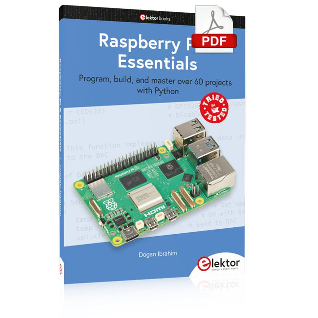
Elektor Digital Raspberry Pi 5 Essentials (E-book)
Program, build, and master over 60 projects with Python The Raspberry Pi 5 is the latest single-board computer from the Raspberry Pi Foundation. It can be used in many applications, such as in audio and video media centers, as a desktop computer, in industrial controllers, robotics, and in many domestic and commercial applications. In addition to the well-established features found in other Raspberry Pi computers, the Raspberry Pi 5 offers Wi-Fi and Bluetooth (classic and BLE), which makes it a perfect match for IoT as well as in remote and Internet-based control and monitoring applications. It is now possible to develop many real-time projects such as audio digital signal processing, real-time digital filtering, real-time digital control and monitoring, and many other real-time operations using this tiny powerhouse. The book starts with an introduction to the Raspberry Pi 5 computer and covers the important topics of accessing the computer locally and remotely. Use of the console language commands as well as accessing and using the desktop GUI are described with working examples. The remaining parts of the book cover many Raspberry Pi 5-based hardware projects using components and devices such as LEDs and buzzers LCDs Ultrasonic sensors Temperature and atmospheric pressure sensors The Sense HAT Camera modules Example projects are given using Wi-Fi and Bluetooth modules to send and receive data from smartphones and PCs, and sending real-time temperature and atmospheric pressure data to the cloud. All projects given in the book have been fully tested for correct operation. Only basic programming and electronics experience are required to follow the projects. Brief descriptions, block diagrams, detailed circuit diagrams, and full Python program listings are given for all projects described.
€ 32,95
Mitglieder: € 29,66
-

Elektor Digital Raspberry Pi Pico Essentials (E-book)
Program, build, and master over 50 projects with MicroPython and the RP2040 microprocessor The Raspberry Pi Pico is a high-performance microcontroller module designed especially for physical computing. Microcontrollers differ from single-board computers, like the Raspberry Pi 4, in not having an operating system. The Raspberry Pi Pico can be programmed to run a single task very efficiently within real-time control and monitoring applications requiring speed. The ‘Pico’ as we call it, is based on the fast, efficient, and low-cost dual-core ARM Cortex-M0+ RP2040 microcontroller chip running at up to 133 MHz and sporting 264 KB of SRAM, and 2 MB of Flash memory. Besides its large memory, the Pico has even more attractive features including a vast number of GPIO pins, and popular interface modules like ADC, SPI, I²C, UART, and PWM. To cap it all, the chip offers fast and accurate timing modules, a hardware debug interface, and an internal temperature sensor. The Raspberry Pi Pico is easily programmed using popular high-level languages such as MicroPython and or C/C++. This book is an introduction to using the Raspberry Pi Pico microcontroller in conjunction with the MicroPython programming language. The Thonny development environment (IDE) is used in all the projects described. There are over 50 working and tested projects in the book, covering the following topics: Installing the MicroPython on Raspberry Pi Pico using a Raspberry Pi or a PC Timer interrupts and external interrupts Analogue-to-digital converter (ADC) projects Using the internal temperature sensor and external temperature sensor chips Datalogging projects PWM, UART, I²C, and SPI projects Using Wi-Fi and apps to communicate with smartphones Using Bluetooth and apps to communicate with smartphones Digital-to-analogue converter (DAC) projects All projects given in the book have been fully tested and are working. Only basic programming and electronics experience is required to follow the projects. Brief descriptions, block diagrams, detailed circuit diagrams, and full MicroPython program listings are given for all projects described. Readers can find the program listings on the Elektor web page created to support the book.
€ 32,95
Mitglieder: € 29,66
-

Peak Peak Atlas ESR70 gold (ESR- und Kapazitätsmessgerät)
Der Peak Atlas ESR70 gold ist eine verbesserte Version des früheren Peak Atlas ESR70 Plus. Er kann alles, was der ESR70 Plus konnte, nur noch besser. Dank neuer Prüfalgorithmen misst er die Kapazität jetzt bis zu 10-mal schneller und über einen größeren Bereich. Dank unseres neuen Triple-Slope-Messsystems wird die Kapazitätsmessung auch viel weniger durch parallele Widerstände oder Leckströme beeinflusst. Mit den mitgelieferten vergoldeten Sonden (abnehmbar) kann der Atlas ESR70 gold den ESR bis zu einer Auflösung von 0,01 Ohm und bis zu 40 Ohm messen. Es kann sogar den ESR von Kondensatoren messen, die sich im Stromkreis befinden. Die Messfühler sind abnehmbar, so dass 2 mm kompatible Messfühler angebracht werden können. Bei verschiedenen ESR-Werten ertönt ein akustisches Warnsignal, so dass Sie viele Tests hintereinander durchführen können, ohne auf das Display schauen zu müssen. Der ESR70 berücksichtigt automatisch den kapazitiven Blindwiderstand, so dass der ESR auch bei Kondensatoren mit niedrigem Wert (bis zu 0,3 uF) genau gemessen werden kann. Features Verwendet eine einzelne AAA-Alkalizelle (im Lieferumfang enthalten). Alphanumerisches LCD mit Hintergrundbeleuchtung. Automatischer Analysestart, wenn Sie die Sonden anwenden. Automatische Kondensatorentladung durch kontrollierte Entladefunktion. ESR-Messung (und niedriger Gleichstromwiderstand) (auch im Schaltkreis). Kapazitive Reaktanz wird automatisch berücksichtigt, um einen genauen ESR zu gewährleisten. Kapazitätsmessung (bei Prüfung außerhalb des Schaltkreises). Akustische Warnungen für verschiedene ESR-Stufen. Erweiterter ESR-Messbereich bis zu 40 Ohm. Optionale Sondenalternativen einfach zu montieren. Neue gold Features Verbessertes LCD mit besserer Hintergrundbeleuchtung. 10x schnellere Kapazitätsmessung für große Kondensatoren. Erweitertes Benutzeroptionensystem. Neues Triple-Slope-Messsystem, um den Einfluss von Parallelwiderstand und/oder Leckstrom auf Kapazitätsmessungen erheblich zu reduzieren. Viel größerer Kapazitätsmessbereich jetzt 0,3 uF bis 90.000 uF (vorher 1 uF bis 22.000 uF). Technische Daten Analyzertyp ESR und Kapazität Komponententypen Kondensatoren (>0,3 uF) ESR-Bereich 0,00 Ohm bis 40,0 Ohm ESR-Auflösung Ab 0,01 Ohm In-Circuit-Verwendung Nur ESR Kapazitätsbereich 0,3 uF bis 90000 uF Batterietyp 1,5-V-Alkali-AAA-Zelle (im Lieferumfang enthalten). Lebensdauer normalerweise 1500 Operationen Anzeigetyp Alphanumerisches LCD (mit Hintergrundbeleuchtung) Lieferumfang Widerstandsmessgerät der äquivalenten Serie ESR70 Extra lange und besonders flexible Prüfkabel (450 mm silikonummanteltes Kabel) 2 mm vergoldete Stecker und Buchsen mit abnehmbaren vergoldeten Krokodilklemmen Umfassende bebilderte Bedienungsanleitung AAA-Alkalizelle Downloads Datasheet (EN) User Guide (DE)
€ 141,61
-

Speciale Elektor / E&M: 33 Progetti Top di Elettronica
Una ricca selezione di articoli dal Mondo Elektor! Gli articoli di questo libro sono una selezione accurata, il "meglio del meglio" di circuiti e progetti recenti, realizzati da tecnici di grande talento provenienti da tutto il mondo. Nel tipico stile di Elektor, questa raccolta offre qualcosa di interessante per tutti, dai progettisti esperti a coloro che praticano l'elettronica nel tempo libero. Sommario Super Servo TesterProva Fino a Quattro Servocomandi, Stand-Alone o in Sistema The TubeUn Insolito Amplificatore a Valvole Cloc 2.0La Sveglia che Avete Sempre Desiderato Stazione Meteo LoRa Low-PowerCostruitevi una Stazione Meteorologica “Long Range” Uscita Video con Microcontrollori (Parte 1)Video Composito Uscita Video con Microcontrollori (Parte 2)Uscita VGA e DVI Un Raspberry Pi Pico come Analizzatore di SpettroFFT su Base Hardware a Basso Costo PIC O’Clock – In Contatto col TempoProgettare un Ricevitore di Segnali Orari SDR Frequenzimetro di Rete ACMisura Frequenza e Tensione della Rete Elettrica Generatore di Funzioni con Arduino NanoNano + Codice = Generatore di Funzioni Monitor CO2Un Approccio Fai-Da-Te per Il Controllo della Qualità dell‘Aria ChatMagLevLa Levitazione Magnetica con AI Alimentatore Lineare Variabile Combinato0…50 V / 0…2 A con Struttura Simmetrica Duale Ricevitore Digitale FM con Arduino e TEA5767Restate in Ascolto con un Arduino Nano Protezione Antigelo per Piante da FruttoCon Registrazione della Temperatura Carico Elettronico con Generatore di clock IntegratoPer Collaudare Alimentatori, Convertitori di Tensione e Batterie 128 Termostato Web con ESP32Mantieni il Vino alla Giusta Temperatura Iniezione di Segnali e di Potenza......per Rilevare le Interruzioni nei Cavi DIY LiPo Supercharger KitDal Prototipo al Mercato di Massa Livella Digitale con Stroboscopio AttivoCalibra il Tuo giradischi con Questo Strumento "Tutto-in-Uno" The Game of Life – 262.144 Modi di GiocareDal Progetto di un Lettore Rilevatore di PerditeCollegato ad Arduino Cloud Orologio di LissajousL’Incedere del Tempo con le Figure di Lissajous Mastermind – Controllato da ArduinoUna Versione Moderna del Classico Gioco di Decifrazione Generatore Audio Analogico 1 kHzOnda Sinusoidale a Bassa Distorsione Aggiorna il tuo Caricabatteria (Parte 1)Non Buttarlo, Modificalo! Aggiorna il tuo Caricabatteria (Parte 2)Non Buttarlo, Modificalo! Sistemi GNSS RTK a Basso CostoCon Accuratezza a Livello Centimetrico Esperimenti a 10 GHz con LNB Satellitari ModificatiSbloccare la Banda X a Basso Costo Telecamera per FerromodellismoInstalla un Modulo ESP32 CAM a Bordo! Monitor di Tensione con MicrocontrolloreProtezione dalla Scarica Profonda per Batterie e Altro Nodo Sensore AutonomoTrasmissione Dati LoRa con Alimentazione a Batterie Solari Layout e Sicurezza sul PCBConsigli per un Progetto Sicuro e Durevole
€ 29,95
Mitglieder: € 26,96
-

Elektor Digital Elektor March/April 2021 (PDF) EN
The Vision and Engineering Behind SparkFun Getting Started with MicroMod Leveling Up Your SparkFun JetBotHow I Expanded the Functionality of My JetBot, Powered by the NVIDIA Jetson Nano Programming an FPGA How to Build a DIY GNSS Reference Station The ClockClock Project Under the Hood: SparkFun Inventor's Kit SparkFun’s Glenn Samala on Product Development and New Ventures Creating Custom Circuit Boards with SparkFun À La Carte Designing with the SparkFun Artemis Getting Started with the Qwiic Ecosystem for Rapid Prototyping Poster - Qwiic Under the Hood: The GreatScott! / Elektor DIY LiPo Supercharger Kit Memorable Electronics from SparkFun Past Perfect Parking with LiDAR Buried Pad PCB Fixing Design to Sale: the SparkFun RTK Surveyor Hello World from the Raspberry Pi Pico and RP2040A Look at Raspberry Pi’s First Microcontroller and Microcontroller Chip DIY Quadrupedal Robots Poster - Micromod RISC-V IoT Development in AWS Using FreeRTOS Libraries Yep, Electronics = Fun!A Conversation Among Electronics Enthusiasts Sparkfun Product Catalog HexadokuThe Original Elektorized Sudoku
€ 7,50
-
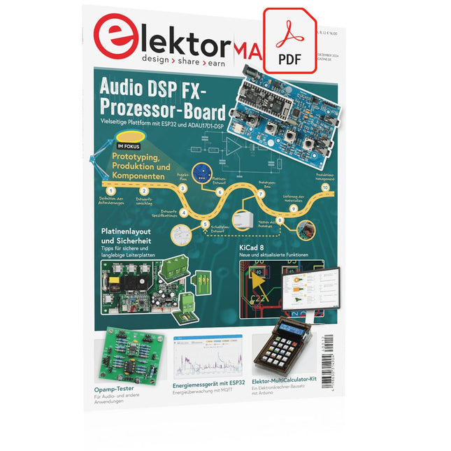
Elektor Digital Elektor 11-12/2024 (PDF)
Diese Ausgabe steht allen GOLD- und GREEN-Mitgliedern auf der ElektorMagazine-Website zum Download bereit! Sie sind noch kein Mitglied? Hier klicken! Audio-DSP-FX-Prozessor-BoardTeil 1: Eigenschaften und Design 50 Jahre Elektor in englischer Sprache KiCad 8Neue und aktualisierte Funktionen MultiCalculator-KitEin Elektronikrechner-Bausatz von Elektor mit Arduino Preiswerte GNSS-RTK-SystemeFür zentimetergenaue Positionsbestimmung Platinenlayout und SicherheitTipps für sichere und langlebige Leiterplatten Opamp-TesterFür Audio- und andere Anwendungen Projekt-Update #4 : Energiemessgerät mit ESP32Energieüberwachung mit MQTT Echtzeit-Spektrumanalyzer mit Waveguide-Technologie und Multi-Schnittstellen-PCsAaronia etabliert neues Produktsegment und präsentiert erste Prototypen auf der electronica in München electronica 2024Highspeed und robuste Board-to Board Steckverbinder InduktivitätenSpulen und Ferrite anwendungsorientiert selektieren EMI-Abschirmung zur Einhaltung der elektromagnetischen Konformität Das ultimative Werkzeug für jeden Elektronik-EnthusiastenUnendliche Möglichkeiten mit Red Pitaya und 1.000+ Click Boards™ Die 100 % durchgängige Flussmittelseele Siglent stellt seine neue Vektornetzwerkanalysator-Plattform SNA6000A vor HDI der MittelklasseEin neuer ökonomischer PCB Pooling Service für hochpolige BGAs Ferngesteuerte IoT-EntwicklungDie einzige Lösung für Fernunterricht und Entwicklung in der Embedded-Industrie Herausforderungen der DFM-Analyse für Flex- und Rigid-Flex-Design Aus dem Leben gegriffenMikrotechnophobie Feliz Natal: 3D-WeihnachtsbaumEine 3D-Platine mit preiswertem 32-Bit-Mikrocontroller Aller Anfang......muss nicht schwer sein: Weiter geht es mit den Opamps! Ein autonomer SensorknotenProjekt-Update #1: Reduzierung der Leerlauf-Stromaufnahme mit externer RTC mit Leistungsschalter 2024: Eine Odyssee in die KIEin Blick zurück in die Zukunft LED-Displays mit dem MAX7219Ein praktischer Ansatz für einen großartigen Chip Projekt 2.0Korrekturen, Updates und Leserbriefe VibroTactile-HandschuheEin Durchbruch für Parkinson-Patienten?
€ 11,90
-
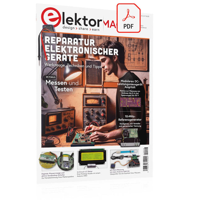
Elektor Digital Elektor 05-06/2024 (PDF)
Diese Ausgabe steht allen GOLD- und GREEN-Mitgliedern auf der ElektorMagazine-Website zum Download bereit! Sie sind noch kein Mitglied? Hier klicken! STM32 Wireless Innovation Design Contest – Die Gewinner stehen fest In-Circuit LC-MeterEine Prototyp-Studie Das modulare DC-Leistungsmessgerät AmpVoltTeil 1: Platine zur Messung von Strömen bis 5 A und Spannungen bis 50 V embedded world 2024 Reparatur von elektronischen GerätenWerkzeuge, Techniken und Tipps Aller Anfang ...muss nicht schwer sein: Wir setzen die Verstärkertheorie fort! Ein einfacher DDS-SignalgeneratorDirekte Digitale Synthese in ihrer reinsten Form Sparkplug im ÜberblickEine Spezifikation für MQTT-Daten Bemerkenswerte BauteileZeile für Zeile: CRTCs Radargesteuerte BeleuchtungAutomatisches Treppenhauslicht mit Anwesenheitsdetektion Digitale Wasserwaage und aktive Stroboskop-Scheibe für PlattenspielerFeinabstimmung Ihres Plattenspielers mit nur einem Gerät Open Source und seine Bedeutung für die Elektronikindustrie (2) M12-Rundsteckverbinder mit A-KodierungErste Wahl für industrielle Anwendungen Arduino-MesslaborEin 8-in-1-Test- und Messgerät für das heimische Elektroniklabor Soundkarte als Betrag/Phase-Impedanz-AnalysatorFür Frequenzen von 100 Hz bis 90 kHz pH-Wert-Messung mit dem Arduino UNO R4Überprüfen Sie die Qualität Ihres Wassers Aus dem Leben gegriffenStartrampe für Pangpong-Popöchen Digitales Speicheroszilloskop FNIRSI 1014DGute Leistung für knappe Budgets 2024: Eine Odyssee in die KIWie man die Objekterkennung zum Laufen bringt 10-MHz-ReferenzgeneratorHochgenau, mit Verteiler und galvanischer Trennung Projekt-Update #2: Energiemessgerät mit ESP32Einige Weiterentwicklungen Projekt 2.0Korrekturen, Updates und Leserbriefe Ein Interview mit Eben Upton, Geschäftsführer von Raspberry PiDer Raspberry Pi 5 und darüber hinaus
€ 11,90
-

Elektor Digital Elektor Novembre/Décembre 2024 (PDF)
Le téléchargement intégral de ce numéro est disponible pour nos membres GOLD et GREEN sur le site Elektor Magazine ! Pas encore membre ? Cliquez ici. Prototypage, production et composants ! carte processeur Audio DSP FXpartie 1 : caractéristiques et conception 50 ans d'Elektor en anglais KiCad 8nouvelles et dernières caractéristiques Elektor @ electronica 2024electronica Fast Forward 2024, des experts sur scène, des forums d'influenceurs, des talk-shows Elektor Lab en direct, et plus encore kit MultiCalculator d'ElektorUn kit de calculatrice basé sur Arduino pour l'électronique systèmes GNSS RTK à faible coûtavec un degré de précision de l'ordre du centimètre routage des Circuits Imprimés et sécuritéConseils pour une conception sure et fiable de vos cartes électroniques testeur d'ampli-oppour les applications audio et autres mise à jour du projet #4 : compteur d'énergie ESP32surveiller l'énergie avec MQTT analyseur de spectre temps-réel à technologie guide d’onde et PC à interfaces multiplesAaronia introduit une nouvelle ligne de produit et présente ses premiers prototypes au salon Electronica de Munich inductances SMTbobines et ferrites – un choix simplifié utilisation d’un blindage EMI pour assurer la conformité à la compatibilité électromagnétique l'outil ultime pour tous les passionnés d’électroniqueDébloquez des possibilités infinies avec Red Pitaya et plus de 1000 Click Boards™ HDI au milieuUn nouveau service PCB-pooling rentable pour des petits BGA défis de l'analyse DFM pour les circuits flexibles et flexibles-rigides outils open-sourcesimulateur d'antennes, gestion des composants, calculatrice, et bien plus Infographie : prototypage et production sur le vifmicrotechnophobie : c’est grave, docteur ? arbre de Noël 3Dcircuit imprimé 3D avec un microcontrôleur 32 bits peu coûteux démarrer en électronique......on continue avec l'ampli-op ! nœud de capteurs autonome (mise à jour du projet #1)Reducing Idle Power Consumption with External RTC and Power Switch 2024 : l'odyssée de l'IAUn regard sur l'avenir afficheurs LED avec le MAX7219Une méthode pratique pour une excellente puce projet 2.0Corrections, mises à jour et courrier des lecteurs gants vibro-tactilesune avancée pour les patients de Parkinson
€ 10,95
-

Paggen Werkzeugtechnik SMD Starter I – Fertigungslinie für Prototypen
Die Prototypen-Fertigungslinie SMD Starter I besteht aus dem Schablonendrucker TSD240, dem SMD-Bestückungsgerät PlaceMAN und dem Reflow-Ofen 3LHR10. Schablonendrucker SD240 (+ Metallrakel 155 mm) Schablonengröße: max. 175 x 255 mm Platinengröße: max. 180 x 240 mm Gerätegröße: 410 x 270 x 110 mm Gewicht: 6,7 kg inkl. Metallrakel 155 mm inkl. 8 Magnete zum Halten der Leiterplatte, 6 davon mit M3-Madenschraube inkl. transparente Platzierhilfe und Faserschreiber Manuelles SMD-Bestückungsgerät PlaceMAN für Standardbauteile inkl. Vakuumpumpe (ohne Zuführungen, Kamera, Monitor und Dispenser) Ausgestattet mit leichtgängigem Bestückungsarm, Bestückungskopf mit Einhandbedienung, Rotation der Z-Achse und automatischer Vakuumabschaltung, inkl. Leiterplattenhalterung, Vakuumeinheit und 2 Bestückungsnadeln mit Gummisaugern. Kapazität an Feeder (nicht im Lieferumfang enthalten) 2x Feederkassette für 10 x 8 mm Rollen links 4x Feederkassette für Stangenfeeder für jeweils 5 Stangen weiter Zuführsysteme sind innerhalb des Bestückungsbereiches möglich, z. B. Strip-Feeder Stecksystem Abmessungen Grundgerät (LxBxH): 765 x 390 x 210 mm Mit Feederkassette für 10 x 8 mm Rollen (LxBxH): 765 x 390 x 210 mm Mit Feederkassette für 10 x 8 mm Rollen und Feederkassette für Stangenfeeder (LxBxH): 765 x 430 x 210 mm (Höhe kann durch die Stangenlänge variieren) Mit Feederkassette für 10 x 8 mm Rollen inkl. Halter für 10 Rollen und Feederkassette für Stangenfeeder (LxBxH): 765 x 430 x 210 mm (Höhe kann durch die Stangenlänge variieren) Technische Daten Gewicht Grundgerät: ca. 6 kg Verfahrweg der Achsen (x,y,z): 470 x 230 x 15 mm Max. Arbeitsbereich: 380 x 240 mm Max. PCB-Größe: 230 x 360 mm Stromversorgung Netzteil: 230/12 V, 800 mA Stromversorgung Vakuumpumpe: 230 V, 6 W 3LHR10 Reflow-Ofen (programmierbar für bleifreie Lötungen mit manueller Schublade und Tablet-Steuerung) Reflow-Ofen mit IR und Konvektionsheizung. Die erzwungene Heißluftkonvektion sorgt für ein gleichmäßiges Temperaturprofil in der gesamten Kammer. Nach dem manuellen Öffnen der Tür werden die Lüfter eingeschaltet und die gelötete Leiterplatte schnell abgekühlt. Kleiner Reflow-Ofen mit manueller Türöffnung Industrie 4.0 bereit, Bluetooth-Kommunikation + Tablet IR + Konvektionsheizung. Android-Anwendung zur Verbindung mit Tablet oder Smartphone 100 verschiedene Benutzerprogramme Lieferumfang: 3LHR10, Tablet mit App, Schutzhülle für Tablet, 4 Leiterplattenhalter, externes Thermoelement, Handbuch im Tablet Anwendung Schließen Sie den Ofen an die Stromversorgung an und schließen Sie die optional erhältliche Absaugung (3LFE10S) an den Abluftstutzen an. Nach dem ersten Einschalten sucht der Ofen nach einem Tablet oder Smartphone. Wenn beide in der Android-App verbunden sind, wählen Sie die Programmierung des Ofens. Hier sind programmierbare Temperatur und Vorheizzeit sowie Temperatur und andere Daten einzustellen. Registrieren Sie sich mit dem Tablet, um den vollen Umfang der Software nutzen zu können. Wenn der Ofen bereits programmiert ist, kann der Benutzer den Vorgang mit Tasten und Anzeige auf der Vorderseite steuern. Nach Abschluss des Reflow-Vorgangs ertönt ein akustisches Signal. Ein Signal wird auch auf dem Tablet/Smartphone angezeigt. Die Schublade muss nun manuell geöffnet werden. Die Android-Anwendung zeigt Prozessstatus, Zeit und Temperatur oder andere Informationen an. Technische Daten Netzanschluss: 230 V, 50 Hz Maximale Leistung: 3100 W Temperaturen: 50-260°C Abmessungen: 510 x 370 x 340 mm Maximales Gewicht: 16 kg Gitterabmessungen: 350 x 220 mm Maximale Abmessungen der Leiterplatte: 300 x 200 mm Maximale Komponentenhöhe auf der Leiterplatte: 50 mm oben, 30 mm unten Lieferumfang Schablonendrucker TSD240 SMD-Bestückungsgerät PlaceMAN Reflow-Ofen 3LHR10
€ 6.549,00
Bestpreis


