
Suchergebnisse für "four OR legged OR allbot"
-

Elektor Labs Elektor Super Servo Tester Kit
Der Elektor Super Servo Tester kann Servos steuern und Servosignale messen. Es können bis zu vier Servokanäle gleichzeitig getestet werden. Der Super Servo Tester wird als Bausatz geliefert. Alle zum Zusammenbau des Super Servo Testers erforderlichen Teile sind im Bausatz enthalten. Für den Zusammenbau des Bausatzes sind grundlegende Lötkenntnisse erforderlich. Der Mikrocontroller ist bereits programmiert. Der Super Servo Tester verfügt über zwei Betriebsmodi: Steuerung/Manuell und Messen/Eingänge. Im Control/Manual Modus generiert der Super Servo Tester an seinen Ausgängen Steuersignale für bis zu vier Servos oder für den Flugregler oder ESC. Die Signale werden über die vier Potentiometer gesteuert. Unter Measure/Inputs misst der Super Servo Tester die an seine Eingänge angeschlossenen Servosignale. Diese Signale können beispielsweise von einem Regler, einem Flugregler, dem Empfänger oder einem anderen Gerät stammen. Die Signale werden auch an die Ausgänge weitergeleitet, um die Servos oder den Flugregler bzw. ESC zu steuern. Die Ergebnisse werden auf dem Display angezeigt. Technische Daten Betriebsmodi Control/Manual & Measure/Inputs Kanäle 3 Servosignaleingänge 4 Servosignalausgänge 4 Alarm Summer & LED Anzeige 0,96' OLED (128 x 32 Pixel) Eingangsspannung an K5 7-12 VDC Eingangsspannung an K1 5-7,5 VDC Eingangsstrom 30 mA (9 VDC an K5, nichts an K1 und K2 angeschlossen) Abmessungen 113 x 66 x 25 mm Gewicht 60 g Lieferumfang Widerstände (0,25 W) R1, R3 1 kΩ, 5% R2, R4, R5, R6, R7, R9, R10 10 kΩ, 5% R8 22 Ω, 5% P1, P2, P3, P4 10 kΩ, lin/B, vertikales Potentiometer Kondensatoren C1 100 µF 16 V C2 10 µF 25 V C3, C4, C7 100 nF C5, C6 22 pF Halbleiter D1 1N5817 D2 LM385Z-2.5 D3 BZX79-C5V1 IC1 7805 IC2 ATmega328P-PU, programmiert LED1 LED, 3 mm, rot T1 2N7000 Außerdem BUZ1 Piezo-Summer mit Oszillator K1, K2 2-reihiger, 12-poliger Pinheader, 90° K5 Barrel jack K4 1-reihige, 4-polige Stiftbuchse K3 2-reihiger, 6-fach geschachtelter Pinheader S1 Slide Switch DPDT S2 Slide Switch SPDT X1 Crystal, 16 MHz 28-polige DIP-Buchse für IC2 Elektor Platine OLED-Display, 0,96', 128 x 32 Pixel, 4-pin I²C-Interface Links Elektor Magazine Elektor Labs
€ 59,95€ 49,95Bestpreis
-

FNIRSI FNIRSI HRM-10 Batterie-Innenwiderstands- und Spannungstester
Der FNIRSI HRM-10 ist ein tragbarer, hochpräziser Batterie-Innenwiderstands- und Spannungstester. Dieses Gerät bietet echte Vierleitermessung und ist sowohl auf Genauigkeit als auch auf Benutzerfreundlichkeit ausgelegt. Es misst automatisch gleichzeitig Innenwiderstands- und Spannungswerte und zeigt die Ergebnisse auf dem HD-Farbdisplay an. Benutzer haben die Möglichkeit, Spannungs- und Widerstandsbereiche manuell an ihre Bedürfnisse anzupassen. Das Gerät verfügt außerdem über einen Sortiermodus, der anhand vom Benutzer festgelegter Schwellenwerte automatisch die guten und schlechten Batterien filtert. Darüber hinaus unterstützt es die Speicherung historischer Daten und ermöglicht den Export von Messdatensätzen im Tabellenformat. Features Hohe Messgenauigkeit Tabellarischer Datenexport Messergebnisse automatisch auswerten 8 Schwellenwerteinstellungen HD-Farbdisplay Klappständer 1000 mAh Lithiumbatterie Technische Daten Spannung Widerstand Messbereich 0-100 V (DC) 0-200 Ω Genauigkeit ±0,5% ±0,5% Ausrüstung Automatisch, 1 V, 10 V, 100 V Automatisch, 20 mΩ, 200 mΩ, 2 Ω, 20 Ω, 200 Ω Frequenz des Gerätetestsignals 1 kHz (AC) Wiederaufladbar USB-C (5 V/1 A) Eingebauter Akku 1000 mAh Lithiumbatterie Benutzerkalibrierung Ja Sortiermodus Ja Verlaufsdatensatz Ja Aufgezeichneter Datenexport Ja Arbeitsumgebung –10°C bis +45°C, relative Luftfeuchtigkeit <80% Speicherumgebung –20°C bis +80°C, relative Luftfeuchtigkeit <80% Abmessungen 158,7 x 80,5 x 28,4 mm Gewicht 225 g Lieferumfang 1x FNIRSI HRM-10 Innenwiderstandstester 1x Clip-Testleitung 1x USB-C Datenkabel 1x Manual Downloads Manual Firmware V0.3
€ 49,12
-

Elektor Labs Elektor Rauscharmes Labornetzteil
Das rauscharme Labornetzteil von Elektor ist ein vollständig analoges, einstellbares, symmetrisches Gerät mittlerer Leistung, das ohne Schalt- oder digitale Komponenten auskommt. Es bietet eine Ausgangsspannung, die zwischen 0 V und ±22 V einstellbar ist, sowie einen Ausgangsstrom, der von 0 A bis 1 A eingestellt werden kann. Da auf jegliche Art von Schalttechnik verzichtet wird, liefert das Design extrem geringes Rauschen. Zur Anzeige beider Ausgangsspannungen und -ströme werden vier kleine analoge Einbauinstrumente mit Drehspulmesswerk verwendet. Die meisten modernen Labornetzgeräte und AC-Adapter arbeiten mit Schaltnetzteiltechnik. Selbst die besten Ausführungen weisen zwangsläufig hochfrequente Restwelligkeit und andere Schaltartefakte am Ausgang auf, die die Prüfung empfindlicher analoger Schaltungen stören und Messungen kleiner Signale beeinträchtigen können. Um dieses Problem zu vermeiden, setzt dieses Konzept auf ein vollständig analoges Netzgerät. Obwohl es weniger effizient ist als vergleichbare Schaltnetzteile, spielt die geringere Effizienz beim Einsatz auf dem Prüfstand kaum eine Rolle und sorgt für sauberere und zuverlässigere Messergebnisse. Da viele analoge Schaltungen eine symmetrische Versorgung benötigen, liefert dieses Design positive und negative Ausgangsspannungen gleicher Höhe. Eine geringfügige Nachjustierung ist möglich, um eventuelle Ungleichgewichte auszugleichen. Selbstverständlich ist auch eine einstellbare Strombegrenzung integriert. Das Kit enthält die für den Aufbau des Netzteils erforderlichen Komponenten, mit Ausnahme der Transformatoren. Technische Daten Ausgangsspannung 0…+22 V, 0, −22 V Ausgangsstrom 0…+1 A, 0…−1 A Rauschen −85 dBV (bei 0,95 A/20 V, B = 22 kHz) −84 dBV (bei 0,95 A/20 V, B > 500 kHz) Restwelligkeit 50 µVRMS (bei 950 mA/20 V, B = 22 kHz, hauptsächlich 100-Hz-Anteil) Lieferumfang 3x Platinen: Regler (PCB-1), Netzfilter (PCB-2) und Transformator (PCB-3) Alle Bauteile mit Ausnahme der Netztransformatoren 4x Drehspulmesswerke Zusätzliche Teile für die Verdrahtung (Drähte, Bananenbuchsen, Kaltgeräte-Netzmodul usw.) Nicht enthalten Die drei Netztransformatoren Ein Gehäuse Stückliste Für die Spannungsregler-Platine (240386-1) Widerstände (250 mW, 1%) R1 = 12 Ω R2, R8, R37, R62 = 1 MΩ R3, R7, R10, R13, R17, R20, R22, R30, R35, R42, R45, R47, R55, R60 = 100 Ω, 600 mW R4, R5 = 4.7 kΩ R6 = 100 kΩ R9, R12, R14, R36, R38, R39, R61, R63, R66, R72, R78, R79 = 10.0 kΩ, 600 mW R11 = 9.76 kΩ, 600 mW R15, R40 = 44.2 kΩ, 600 mW R16, R41, R77 = 1 kΩ R18, R43 = 1.5 kΩ, 1 W, 5% R19, R44 = 470 Ω, 1 W, 5% R21, R46 = 330 Ω, 600 mW R23, R24, R48, R49 = 1.0 Ω, 1 W R25, R50 = 1 kΩ, 1 W, 5% R26, R28, R51, R53 = 1.000 kΩ 0.1%, 15 ppm/C R27, R29, R52, R54 = 10.00 kΩ 0.1%, 15 ppm/C R31, R56 = 1.2 kΩ, 1 W, 5% R32, R57 = 47 kΩ R33, R58 = 270 Ω R34, R59 = 27 kΩ R64, R69 = 12.0 kΩ R65 = 3.0 kΩ, 600 mW R67, R80 = 470 Ω, 600 mW R68, R70 = 6.8 kΩ, 600 mW R71 = 30.0 kΩ,, 600 mW R73, R74, R75, R76 = 10 MΩ P1, P2, P3 = 10 kΩ, 200 mW, 20%, potentiometer, 1 turns, single, lin., panel mount P4, P5 = 500 Ω, 500 mW, 10%, trimmer, 25 turns, 3296Y-1-501LF Bourns P6, P7 = 10 kΩ, 500 mW, 10%, trimmer, 25 turns, 3296Y-1-501LF Bourns Kondensatoren C1 = 100 nF, 50 V, 10%, ceramic X7R, LS 5 mm C2, C3, C6, C7, C30 = 10 µF, 63V, 20%, LS 2.5 mm, 3000hours@105°C C4, C5, C8, C9, C13, C14, C18, C19, C23, C24, C28, C29, C31, C32, C38, C39 = 100 nF, 250 V, 10%, PET, LS 7.5 mm C10, C20 = 47 nF, 100 V, 5%, PET, LS 5 mm C11, C21 = 10 nF, 100 V, 5%, PET, LS 5 mm C12, C22 = 220 µF, 35 V, 20%, 0.024 Ω, LS2.5/3.5 mm, Ir 3.4 A, 2000hours@125°C, polymer C15, C25 = 120 µF, 50 V, 20%, ESR 0.02 Ω, Diam. 10 mm max., LS 5 mm C16, C26 = 15 nF, 100 V, 5%, PET, LS 5 mm C17, C27 = 47 nF, 100 V, 5%, PET, LS 5 mm C33, C34 = 22 µF, 50 V, 20%, LS 2 mm, 10000 hours @ 105°C C35, C36, C44, C45 = 1 µF, 100 V, 10%, LS 5 mm, ceramic X7R C37 = 100 uF, 50 V, 20%. LS 3.5 mm C40, C41, C42, C43, C46, C47, C48, C49 = 1000 µF, 50 V, 20%, LS 5/7.5 mm, Ir 3.32 A, 10000hours@105°C, D 16 mm C50, C51, C52, C53 = 47 nF, 100 V, 10%, ceramic X7R, LS 5 mm Induktivitäten L1, L2 = 4.7 µH, 3.2 A, 0.033 Ω, LS 5 mm, RLB0914-4R7ML Bourns L3 = Commom mode choke, 14.5 mH, 3 A, SSRH24NH-30145 Kemet Halbleiter D1, D2, D3, D4, D5, D9, D10, D11, D15 = BAT85, DO-34 D6, D7, D12, D13 = SR560, DO-201AD D8, D14, D16 = 1N4148, DO-35 D17 = Zenerdiode, 5.6 V, 0.5 W, DO-41 D18, D19 = 1N4004, DO-41 D20, D21 D22, D23 = V30100CI-M3/P, dual common cathode, TO-220 D24 = Zener diode, 30 V, 1 W, DO-41 LED1, LED2 = LED, red, T-1 (3 mm) LED3, LED4 = LED, green, T-1 (3 mm) TVS1, TVS2 = BZW50-33B, R6 T1, T2, T4 = BC337.25, TO-92 T3 = NJW0302G, TO-3P T5, T6, T8 = BC327.25, TO-92 T7 = NJW0281G, TO-3P T9 = BD139, TO-126 (SOT-32) IC1 = LM334Z, TO-92 IC2 = LM4040AIZ-5.0/NOPB, TO-92 (TO-226AA-3) IC3, IC4 = OPA2992IDR, SOIC-8 IC5, IC6 = OPA4992IDR, SOIC-14 IC7 = OPA992IDBVR, SOT-23-5 IC8 = LM339N, DIP-14 IC9 = LM317, TO-220 IC10 = LM337, TO-220 Sonstiges F1, F2 = 5×20 mm fuse, 1.6 A, fast acting HS1, HS2 = Heatsink MC33271 (for T3/T7), 2.7°C/W, PCB mount, height 63.5 mm K1, K4 = 3-way screw terminal block, LS 3.5 mm, max. 1.5 mm² K2, K3 = 3-way screw terminal block, LS 3.5 mm, max. 1 mm² M1, M3 = Moving coil meter, Range 30 V, type 91C4, 45×45 mm M2, M4 = Moving coil meter, Range 1 A, type 91C4, 45×45 mm² RE1 = Relay DPDT,5V, UA2-5NU Verschiedenes 3× 3-way screw terminal block, LS 3.5 mm, max. 1 mm² (for P1, P2, P3) 4× Pin header, 1×2, vertical, pitch 2.54 mm (for LED1, LED2, LED3, LED4) 4× Pin socket, 1×2, vertical. pitch 2.54 mm (for LED1, LED2, LED3, LED4) 2× Heatsink FK222SA220, 20°C/W, PCB mount (for IC9 & IC10) 2× Mica thermal pad for TO-220, 12×18×0.05 mm (for IC9 & IC10) 2× Insulating bushing IB 6, TO-220 (for IC9 & IC10) 2× Ceramic thermal pad, 23×20×2 mm (for T3 & T7) 2× PCB Fuse Holder, for 5×20 mm fuse, 10 A (for F1, F2) 2× Cover for PCB Fuse Holder, transparent (for F1, F2) 2× 2-way screw terminal block, LS 3.5 mm, max. 1 mm² (for M1 & M3) 2× 2-way screw terminal block, LS 3.5 mm, max. 1.5 mm² (for M2 & M4) 8× M3 solder lug, thickness 0.35 mm (for M1…M4) M4 solder lug, thickness 0.35 mm (to connect 4 mm banana connectors) Screened cable, 1 pair, 2×24 AWG/0.22 mm², 1 m (for P1, P2 & P3) IC socket, DIP, 14 contacts (for IC8) M3 washer, plain, steel M3 screw, 16 mm, steel, pan head M3 nut M3 spring washer 50 mm M3 standoff, steel, male-female 12 mm M3 standoff, steel, male-female 10 mm M3 standoff, steel, male-female M3 screw, 8 mm, steel, pan head Für die Netzfilter-Platine (240386-2) Widerstand R1 = 220 kΩ, 1 W, 500 V, 5% Kondensatoren C1, C2 = 470 nF, 305 VAC, Class X2, 11 × 27 mm max., LS 15/22.5 mm C3, C4, C5, C6 = 2.2 nF, 300 VAC, Class Y2, 13 × 4 mm, LS 10 mm, PP Induktivitäten L1, L2 = Common-mode choke, 6.8 mH, 1.7 A, TDK B82732R2172B030 Halbleiter MOV1 = TVS varistor, 300 VAC, S14K300 (230 VAC, B72214S0301K101) and SK14K150 (150 VAC, B72214S0151K101) Sonstiges K1, K2 = 3-way screw terminal block, LS 7.62 mm F1 = Time-delay fuse, 0.5 A (230 VAC) or 1 A (115 VAC) Verschiedenes 1× Fuse holder, 5×20 mm, 10 A, 500 VAC 1× Transparent fuse cover 4× 10 mm M3 standoff, steel, male–female 4× M3 screw, 8 mm, steel, pan head 4× M3 nut Für die Transformator-Platine (240386-3) Widerstände R1, R2 = 2.7 kΩ, 600 mW, 1% R3 = 10.0 kΩ, 600 mW, 1% Kondensator C1 = 220 µF, 50 V, 20%, Ø10 mm, LS 5 mm, 4000 h @ 105°C Transformatoren (nicht im Lieferumfang dieses Kits enthalten!) TR1, TR2, TR3 = 2×7 V, 25 VA, PCB-mounted toroid, 70060K Talema Halbleiter D1–D4 = 1N4148, DO-35 D5, D6 = 1N4004, DO-41 D7 = Zener 5.6 V, 1.3 W, DO-41 LED1 = LED, red, T-1 (3 mm) IC1, IC2 = MOC8021M, CTR ≥ 1000%, DIP-6 Sonstiges F1, F2, F3 = 160 mA time-delay fuse (230 VAC) or 315 mA time-delay fuse (115 VAC) K1 = 2-way screw terminal block, LS 7.62 mm K2 = 3-way screw terminal block, LS 3.5 mm, max 1.5 mm² K3, K4 = 3-way screw terminal block, LS 3.5 mm, max 1 mm² RE1, RE2 = Relay DPDT, 5 A/250 VAC / 24 VDC Verschiedenes 1× Pin header 1×2, pitch 2.54 mm + matching socket for LED1 3× Fuse holder 5 × 20 mm, 10 A, 500 VAC + transparent cover 3× M4 screw, 8 mm, pan head + washer for TR1-TR3 8× M3 screw, 8 mm, pan head + nut + washer 8× 10 mm M3 standoff, steel, male–female 2× IC socket, DIP-6 for IC1 & IC2 Weitere Bauteile 1 m red insulated wire, stranded, 1.5 mm² 0.5 m blue insulated wire, stranded, 1.5 mm² 0.5 m black insulated wire, stranded, 1.5 mm², 0.5 m 2 m red insulated wire, stranded, D 0.56 mm (0.25 mm²) 2 m black insulated wire, stranded, D 0.56 mm (0.25 mm²) 0.5 m Multicore Cable, Flexible, 3 Core, 0.75 mm² (24 x 0.2 mm) Red banana socket Black banana socket Blue banana socket Green banana socket IEC Power Entry Module with switch, IEC C14 3 crimp terminals, FASTON, 4.75 x 0.81 mm 3 knobs Links Elektor Labs JumpStarter Page Artikel (Teil 1) Artikel (Teil 2)
€ 299,00€ 249,00Bestpreis
-
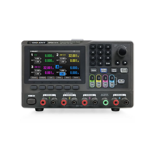
Siglent Siglent SPD4121X 4-Kanal Netzteil (285 W)
The Siglent SPD4121X is a 4-channel DC Linear Programmable Power Supply equipped with a 4.3-inch TFT-LCD display, friendly human-machine interface, and excellent performance indicators. Real-time waveform display provides engineers with an informative user interface. SPD4121X offers a total output power of 285 W with a resolution of 1 mV/1 mA. The maximum voltage and current for each channel are as follows: CH1: 15 V/1.5 A CH2: 12 V/10 A CH3: 12 V/10 A CH4: 15 V/1.5 A Features Rated output power: 285 W Rated voltage: 32 V, 12 V, 30 V Up to four high-precision power supplies with independent controllable outputs, supporting CH2 and CH3 series and parallel connections Clear graphical interface with waveform and timer display modes 5-digit voltage and current display with minimum resolution of 1 mV, 1 mA Fast output response time: <50us The high current channel support remote voltage compensation sense function. The maximum compensation voltage is 0.6 V Overvoltage protection and overcurrent protection or safe and accurate operation Equipped with a 4.3-inch TFT-LCD display (480 x 272 resolution) USB and LAN standard communication USB-GPIB module is optional Excellent channel density with up to 4 channels in a 3U half rack package Internal data storage for setups and parameters Embedded Web Server with instrument communication that doesn’t require software installation Fully SCPI programming command set support as well as a LabView driver for remote control and system automation Technische Daten SPD4323X SPD4121X SPD4306X Channel Output CH1: Voltage 0 to 6 V Current 0 to 3.2 ACH2: Voltage 0 to 32 V Current 0 to 3.2 ACH3: Voltage 0 to 32 V Current 0 to 3.2 ACH4: Voltage 0 to 6 V Current 0 to 3.2 A CH1: Voltage 0 to 15 V Current 0 to 1.5 ACH2: Voltage 0 to 12 V Current 0 to 10 ACH3: Voltage 0 to 12 V Current 0 to 10 ACH4: Voltage 0 to 15 V Current 0 to 1.5 A CH1: Voltage 0 to 15 V Current 0 to 1.5 ACH2: Voltage 0 to 30 V Current 0 to 6 ACH3: Voltage 0 to 30 V Current 0 to 6 ACH4: Voltage 0 to 15 V Current 0 to 1 A Resolution 1 mV, 1 mA 1 mV, 1 mA 1 mV, 1 mA Setting Accuracy Voltage: ±(0.03% of reading+10) mV, Current: ±(0.3% of reading+10) mA Voltage: ±(0.03% of reading+10) mV, Current: ±(0.3% of reading+10) mA Voltage: ±(0.03% of reading+10) mV, Current: ±(0.3% of reading+10) mA Readback Accuracy Voltage: ±(0.03% of reading+10) mV, Current: ±(0.3% of reading+10) mA Voltage: ±(0.03% of reading+10) mV, Current: ±(0.3% of reading+10) mA Voltage: ±(0.03% of reading+10) mV, Current: ±(0.3% of reading+10) mA Display 4.3" TFT-LCD 5-digit voltage and current display 4.3" TFT-LCD 5-digit voltage and current display 4.3" TFT-LCD 5-digit voltage and current display Output power 240 W 285 W 400 W Lieferumfang 1x Siglent SPD4121X Power Supply 1x Power cord (EU) 1x Output test cord (3 A) 1x USB cable 1x Quick start guide Downloads Datasheet Manual Quick start
€ 871,20
Bestpreis
-

Raspberry Pi Foundation FPC Kamera-Kabel für Raspberry Pi 5 (500 mm)
Der Raspberry Pi 5 verfügt über zwei vierspurige MIPI-Anschlüsse, von denen jeder entweder eine Kamera oder ein Display unterstützen kann. Diese Anschlüsse verwenden dasselbe 22-polige "Mini"-FPC-Format mit 0,5 mm Raster wie das Compute Module Development Kit und erfordern Adapterkabel für den Anschluss an die 15-poligen "Standard"-Anschlüsse mit 1 mm Raster an aktuellen Raspberry Pi Kamera- und Display-Produkten. Diese Mini-zu-Standard-Adapterkabel für Kameras und Displays (beachten Sie, dass ein Kamerakabel nicht mit einem Display verwendet werden sollte und umgekehrt) sind in den Längen 200 mm, 300 mm und 500 mm erhältlich.
€ 3,95€ 1,58Bestpreis
-

Siglent Siglent SDS1204X-E 4-Kanal Oszilloskop (200 MHz)
Das Siglent SDS1204X-E ist ein leistungsstarkes 200-MHz-Vierkanal-Oszilloskop, das auf der gleichen Plattform wie das sehr beliebte SDS1202X-E basiert, jedoch mehrere wesentliche Verbesserungen aufweist, darunter zwei 1-GSa/s-ADCs und zwei 14-Mpt-Speichermodule. Die Wellenform-Erfassungsraten betragen bis zu 100.000 Wfms/s im Normalmodus und 400.000 Wfms/s im Sequenzmodus. Die SDS1000X-E-Zielfernrohre verfügen über ein großes 7-Zoll-Farbdisplay mit 256 Stufen und Funktionen zur Intensitätsabstufung und Farbtemperatur. Technische Daten Bandbreite 200 MHz Abtastrate (max.) 1 GSa/s Kanäle 2CH+EXT 4CH Speichertiefe (max.) 7 Mpts/CH (kein Interleave-Modus); 14 Mpts/CH (Interleave-Modus) Wellenform-Erfassungsrate (max.) 100.000 Wfms/s (Normalmodus), 400.000 Wfms/s (Sequenzmodus) Triggertypen Flanke, Steigung, Impulsbreite, Fenster, Runt, Intervall, Dropout, Muster, Video Serieller Trigger (Standard) I 2 C, SPI, UART/RS232, CAN, LIN Dekodierungstyp (Standard) I 2 C, SPI, UART/RS232, CAN, LIN 16 digitale Kanäle (nur Vierkanalserie, Option) Maximale Wellenform-Erfassungsrate bis zu 1 GSa/s, Aufzeichnungslänge bis zu 14 Mpts/CH USB-AWG-Modul (nur Vierkanalserie, Option) Ein Kanal, 25 MHz, Abtastrate 125 MHz, Wellenlänge 16 kpts Bode-Diagramm (nur Vierkanalserie) Mindeststartfrequenz 10 Hz, Mindestscanbandbreite 500 Hz, maximale Scan-Bandbreite von 120 MHz (abhängig von Oszilloskop und AWG-Bandbreite), 500 maximale Scanfrequenzpunkte USB-WLAN-Adapter (nur Vierkanalserie, Option) 802.11b/g/b, WPA-PSK, der Adapter muss von Siglent geliefert werden, um eine ordnungsgemäße Funktion zu gewährleisten Downloads Datasheet Manual Programming Guide
€ 781,44
Bestpreis
-
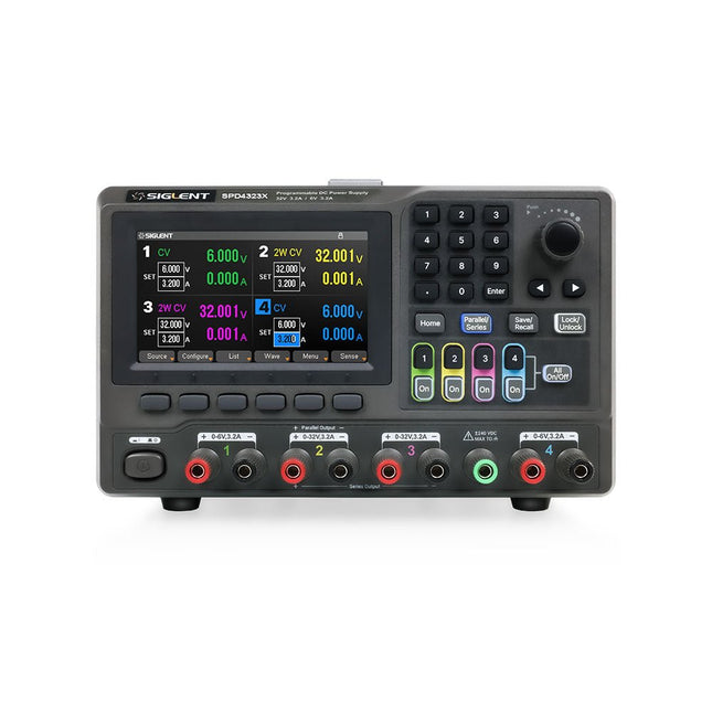
Siglent Siglent SPD4323X 4-Kanal Netzteil (240 W)
The Siglent SPD4323X is a 4-channel DC Linear Programmable Power Supply equipped with a 4.3-inch TFT-LCD display, friendly human-machine interface, and excellent performance indicators. Real-time waveform display provides engineers with an informative user interface. SPD4323X offers a total output power of 240 W with a resolution of 1 mV/1 mA. The maximum voltage and current for each channel are as follows: CH1: 6 V/3.2 A CH2: 32 V/3.2 A CH3: 32 V/3.2 A CH4: 6 V/3.2 A Features Rated output power: 240 W Rated voltage: 32 V, 12 V, 30 V Up to four high-precision power supplies with independent controllable outputs, supporting CH2 and CH3 series and parallel connections Clear graphical interface with waveform and timer display modes 5-digit voltage and current display with minimum resolution of 1 mV, 1 mA Fast output response time: <50us The high current channel support remote voltage compensation sense function. The maximum compensation voltage is 0.6 V Overvoltage protection and overcurrent protection or safe and accurate operation Equipped with a 4.3-inch TFT-LCD display (480 x 272 resolution) USB and LAN standard communication USB-GPIB module is optional Excellent channel density with up to 4 channels in a 3U half rack package Internal data storage for setups and parameters Embedded Web Server with instrument communication that doesn’t require software installation Fully SCPI programming command set support as well as a LabView driver for remote control and system automation Technische Daten SPD4323X SPD4121X SPD4306X Channel Output CH1: Voltage 0 to 6 V Current 0 to 3.2 ACH2: Voltage 0 to 32 V Current 0 to 3.2 ACH3: Voltage 0 to 32 V Current 0 to 3.2 ACH4: Voltage 0 to 6 V Current 0 to 3.2 A CH1: Voltage 0 to 15 V Current 0 to 1.5 ACH2: Voltage 0 to 12 V Current 0 to 10 ACH3: Voltage 0 to 12 V Current 0 to 10 ACH4: Voltage 0 to 15 V Current 0 to 1.5 A CH1: Voltage 0 to 15 V Current 0 to 1.5 ACH2: Voltage 0 to 30 V Current 0 to 6 ACH3: Voltage 0 to 30 V Current 0 to 6 ACH4: Voltage 0 to 15 V Current 0 to 1 A Resolution 1 mV, 1 mA 1 mV, 1 mA 1 mV, 1 mA Setting Accuracy Voltage: ±(0.03% of reading+10) mV, Current: ±(0.3% of reading+10) mA Voltage: ±(0.03% of reading+10) mV, Current: ±(0.3% of reading+10) mA Voltage: ±(0.03% of reading+10) mV, Current: ±(0.3% of reading+10) mA Readback Accuracy Voltage: ±(0.03% of reading+10) mV, Current: ±(0.3% of reading+10) mA Voltage: ±(0.03% of reading+10) mV, Current: ±(0.3% of reading+10) mA Voltage: ±(0.03% of reading+10) mV, Current: ±(0.3% of reading+10) mA Display 4.3" TFT-LCD 5-digit voltage and current display 4.3" TFT-LCD 5-digit voltage and current display 4.3" TFT-LCD 5-digit voltage and current display Output power 240 W 285 W 400 W Lieferumfang 1x Siglent SPD4323X Power Supply 1x Power cord (EU) 1x Output test cord (3 A) 1x USB cable 1x Quick start guide Downloads Datasheet Manual Quick start
€ 762,30
Bestpreis
-

Siglent Siglent SPD4306X 4-Kanal Netzteil (400 W)
The Siglent SPD4306X is a 4-channel DC Linear Programmable Power Supply equipped with a 4.3-inch TFT-LCD display, friendly human-machine interface, and excellent performance indicators. Real-time waveform display provides engineers with an informative user interface. SPD4306X offers a total output power of 400 W with a resolution of 1 mV/1 mA. The maximum voltage and current for each channel are as follows: CH1: 15 V/1.5 A CH2: 30 V/6 A CH3: 30 V/6 A CH4: 15 V/1 A Features Rated output power: 400 W Rated voltage: 32 V, 12 V, 30 V Up to four high-precision power supplies with independent controllable outputs, supporting CH2 and CH3 series and parallel connections Clear graphical interface with waveform and timer display modes 5-digit voltage and current display with minimum resolution of 1 mV, 1 mA Fast output response time: <50us The high current channel support remote voltage compensation sense function. The maximum compensation voltage is 0.6 V Overvoltage protection and overcurrent protection or safe and accurate operation Equipped with a 4.3-inch TFT-LCD display (480 x 272 resolution) USB and LAN standard communication USB-GPIB module is optional Excellent channel density with up to 4 channels in a 3U half rack package Internal data storage for setups and parameters Embedded Web Server with instrument communication that doesn’t require software installation Fully SCPI programming command set support as well as a LabView driver for remote control and system automation Technische Daten SPD4323X SPD4121X SPD4306X Channel Output CH1: Voltage 0 to 6 V Current 0 to 3.2 ACH2: Voltage 0 to 32 V Current 0 to 3.2 ACH3: Voltage 0 to 32 V Current 0 to 3.2 ACH4: Voltage 0 to 6 V Current 0 to 3.2 A CH1: Voltage 0 to 15 V Current 0 to 1.5 ACH2: Voltage 0 to 12 V Current 0 to 10 ACH3: Voltage 0 to 12 V Current 0 to 10 ACH4: Voltage 0 to 15 V Current 0 to 1.5 A CH1: Voltage 0 to 15 V Current 0 to 1.5 ACH2: Voltage 0 to 30 V Current 0 to 6 ACH3: Voltage 0 to 30 V Current 0 to 6 ACH4: Voltage 0 to 15 V Current 0 to 1 A Resolution 1 mV, 1 mA 1 mV, 1 mA 1 mV, 1 mA Setting Accuracy Voltage: ±(0.03% of reading+10) mV, Current: ±(0.3% of reading+10) mA Voltage: ±(0.03% of reading+10) mV, Current: ±(0.3% of reading+10) mA Voltage: ±(0.03% of reading+10) mV, Current: ±(0.3% of reading+10) mA Readback Accuracy Voltage: ±(0.03% of reading+10) mV, Current: ±(0.3% of reading+10) mA Voltage: ±(0.03% of reading+10) mV, Current: ±(0.3% of reading+10) mA Voltage: ±(0.03% of reading+10) mV, Current: ±(0.3% of reading+10) mA Display 4.3" TFT-LCD 5-digit voltage and current display 4.3" TFT-LCD 5-digit voltage and current display 4.3" TFT-LCD 5-digit voltage and current display Output power 240 W 285 W 400 W Lieferumfang 1x Siglent SPD4306X Power Supply 1x Power cord (EU) 1x Output test cord (3 A) 1x USB cable 1x Quick start guide Downloads Datasheet Manual Quick start
€ 1.101,10
Bestpreis
-

Siglent Siglent SDS814X HD 4-Kanal Oszilloskop (100 MHz)
The Siglent SDS814X HD digital storage oscilloscope is based on 2 GSa/s, 12-bit Analog-Digital Converters and front ends with excellent noise floor performance. With a 100 MHz bandwidth, and a maximum record length of 50 Mpts, and the capability to analyze 4 analog channels alongside 16 digital channels, the SDS814X HD is perfectly suited for mixed signal analysis. Features 12-bit High Resolution 12-bit Analog-Digital Convertors with sample rate up to 2 GSa/s Front ends with 70 μVrms noise floor @ 100 MHz bandwidth 2/4 analog channels, up to 700 MHz bandwidth SPO technology Waveform capture rate up to 80,000 wfm/s (normal mode), and 500,000 wfm/s (sequence mode) Supports 256-level intensity grading and color temperature display modes. Up to 50 Mpts record length Digital trigger system Intelligent trigger: Edge, Slope, Pulse width, Window, Runt, Interval, Dropout, Pattern, Video (HDTV supported), Qualified, Nth edge, Delay, Setup/Hold time. Serial bus triggering and decoder, supports protocols I²C, SPI, UART, CAN, LIN. Segmented acquisition (Sequence) mode, dividing the maximum record length into multiple segments (up to 80,000), according to trigger conditions set by the user, with a very small dead time between segments to capture the qualifying event. History waveform record (History) function, the maximum recorded waveform length is 80,000 frames. Automatic measurements on 50+ parameters, supports statistics with histogram, track, trend, Gating measurement, and measurements on Math, History and Ref. 4 Math traces (2 Mpts FFT, addition, subtraction, multiplication, division, integration, differential, square root, etc.), supports formula editor. Abundant data analysis functions such as Search, Navigate, Counter, Bode plot and Power Analysis High Speed hardware-based Mask Test function, with Mask Editor tool for creating user-defined masks 16 digital channels (optional) 25 MHz waveform generator (optional) 7" TFT-LCD display with 1024 x 600 resolution; Capacitive touch screen supports multi-touch gestures. Interfaces include: USB Hosts, USB Device (USBTMC), LAN (VXI-11/Telnet/Socket), Pass/Fail, Trigger Out Built-in web server supports remote control over the LAN port using a web browser. Supports SCPI remote control commands. Supports external mouse and keyboard. Supports NTP. Technische Daten Analog Channels 4 Bandwidth 100 MHz Vertical resolution 12-bit Sample rate (Max.) One channel mode: 2 GSa/sTwo channel mode: 1 GSa/sFour channel mode: 500 MSa/s Memory depth (Max.) One channel mode: 50 Mpts/chTwo channel mode: 25 Mpts/chFour channel mode: 10Mpts/ch Waveform capture rate (Max.) Normal mode: 80,000 wfm/sSequence mode: 500,000 wfm/s Trigger type Edge, Slope, Pulse width, Window, Runt, Interval, Dropout, Pattern, Video, Qualified, Nth edge, Delay, Setup/Hold time, Serial Serial trigger and decode (Standard) I²C, SPI, UART, CAN, LIN Measurement 50+ parameters, statistics, histogram, trend, and track supported Math 4 traces 2 Mpts FFT, Filter, +, -, x, ÷, ∫dt, d/dt, √, Identity, Negation, Absolute, Sign, ex, 10x, ln, lg, Interpolation, MaxHold, MinHold, ERES, Average. Supports formula editor Data analysis Search, Navigate, History, Mask Test, Counter, Bode plot, and Power Analysis Digital channel (optional) 16-channel; maximum sample rate up to 1 GSa/s; record length up to 10 Mpts USB AWG module (option) One channel, 25 MHz, sample rate of 125 MHz, wave length of 16 kpts, isolated output I/O 2x USB 2.0 Host, USB 2.0 Device, 10/100 M LAN, Auxiliary output (TRIG OUT, PASS/FAIL), SBUS (Siglent MSO) Probe (Standard) Passive probe PB470 for each channel Display 7 TFT-LCD with capacitive touch screen (1024x600) Lieferumfang 1x Siglent SDS814X Oscilloscope 4x Passive probe (100 MHz) PP510 1x Power cord (EU) 1x USB cable 1x Certificate of calibration 1x Quick start Downloads Datasheet Manual Programming guide
€ 586,85
Bestpreis
-

OWON OWON XDM2041 True RMS Multimeter
The OWON XDM2041 is a low-cost, high-precision benchtop multimeter. The meter has a True RMS function to measure the AC voltage and current and it has a reading speed of up to 65 values per second. Also, the XDM2041 is equipped with functions such as measuring 2-wire and 4-wire resistance. The XDM2041 is able to store data internally in the memory of the meter and display it on the 3.7" high-resolution LCD display. Up to 1000 points can be stored and the time interval can be varied from 15ms to 9999s. By means of the RS232 port on the back of the device, the meter can be programmed and controlled via SCPI. Technische Daten Measurement Range Resolution Accuracy ±(% of reading + LSB) DC Voltage 50.000mV 0.001mV 0.1%+10 500.00mV 0.01mV 0.025%+5 5.0000V 0.0001V 0.025%+5 50.000V 0.001V 0.03%+5 500.00V 0.01V 0.1%+5 1000.0V 0.1V 0.1%+5 AC Voltage 500mv-750v 20Hz~45Hz 1%+30 45Hz~65Hz 0.5%+30 65Hz~1KHz 0.7%+30 DC Current 500uA 0.01uA 0.15%+20 5000uA 0.1uA 0.15%+10 50mA 0.001mA 0.15%+20 500mA 0.01mA 0.15%+10 5A 0.0001A 0.5%+10 10A 0.001A 0.5%+10 AC Current 500uA-500mA 20 Hz-1 kHz 0.5%+20 5A-10A 1.5%+20 Resistance 500Ω 0.01Ω 0.1%+10 5KΩ 0.0001KΩ 0.1%+5 50KΩ 0.001KΩ 0.1%+5 500KΩ 0.01KΩ 0.1%+5 5MΩ 0.0001MΩ 0.25%+5 50MΩ 0.001MΩ 0.1%+10 Four-wire resistance 500Ω 0.01Ω 0.1%+10 5KΩ 0.0001KΩ 0.1%+5 50KΩ 0.001KΩ 0.1%+5 Measurement Range Resolution Accuracy ±(% of reading + % of range) Frequency 10.000Hz-60MHz / ±(0.2%+8) Capacitance 50nF-500uF / 2.5%+5 5mF-50mF 5%+8 Diode 3.0000 V 0.0001V / Continuity 1000 Ω 0.1Ω / Temperature K type,PT100 Display 55,000 Data-logging Function Logging Duration 15ms-9999s Logging Length 1,000 points Lieferumfang 1x OWON XDM2041 Multimeter 2x Multimeter leads 2x Alligator clips 1x Fuse 1x Manual Downloads User manual Programming manual PC software
€ 152,32
-

Uni-Trend UNI-T UT622E LCR-Meter
Das tragbare LCR-Meter UT622E zeichnet sich durch leistungsstarke Funktionen, hohe Genauigkeit, hohe Geschwindigkeit und lange Standby-Zeit aus. Mit einem klaren und intuitiven 2,8-Zoll-TFT-LCD-Display, einem wiederaufladbaren Akku mit großer Kapazität und einer Testfrequenz von 100 kHz kann das Messgerät bei jeder Gelegenheit für dauerhaft genaue und bequeme Messungen verwendet werden. Es eignet sich für die Messung und Prüfung von Induktivität, Kapazität und Widerstand in Labors, Produktionslinien, Wartungsstellen usw. Features Max. Testfrequenz: 100 kHz Genauigkeit: 0,1% Anzeigeanzahl: 99999 Max. Testrate: 20 mal/s DCR: Ja Konnektivität: Mini-USB Display: 2,8" TFT-LCD Technische Daten Testfrequenz 100 Hz, 120 Hz, 1 kHz, 10 kHz, 100 kHz Teststufe 0,1 Vrms, 0,3 Vrms, 1 Vrms Ausgangsimpedanz 100 Ω Messparameter Primär: L/C/R/Z/DCRSekundär: D/Q/Θ/ESR DSR-Geschwindigkeitstest Schnell (20 Mal/s), mittel (5 Mal/s) oder langsam (2 Mal/s) Bereich Auto/Hold Toleranzbereich 1%~20% Äquivalenter Modus Serie/Parallel Verbindung wird gelöscht Unterbrechung/Kurzschluss Sicherung der Testanschlüsse 0,1 A/250 V Kommunikationsschnittstelle Mini-USB MAX Lesewert der Primärparameter 99999 MIN-Auflösung 0,0001 Maximale Genauigkeit 0,10% L 0,00 µH~99,999 H C 0,00 pF~99,999 mF Z/R 0,0000 Ω~9,9999 MΩ ESR 0,0000 Ω~999,99 Ω D 0,0000~9,9999 Q 0,0000~99999 Θ -179,9°~179,9° DCR 0,01 mΩ~20,000 MΩ Stromversorgung 3,7 V/1800 mAh Lithium-Polymer-Akku Display 2,8-Zoll-TFT-LCD (320 x 240) Abmessungen 93 x 192 x 44 mm Gewicht 420 g Lieferumfang UT622E LCR-Meter Kurzschluss auf der Platine Kelvin-Messleitungen mit vier Anschlüssen USB-Kabel Manual Downloads Datasheet Manual Software
€ 320,11
-

Siglent Siglent SDS822X HD 2-Kanal Oszilloskop (200 MHz)
The Siglent SDS822X HD digital storage oscilloscope is based on 2 GSa/s, 12-bit Analog-Digital Converters and front ends with excellent noise floor performance. With a 200 MHz bandwidth, and a maximum record length of 100 Mpts, and the capability to analyze 2 analog channels alongside 16 digital channels, the SDS822X HD is perfectly suited for mixed signal analysis. Features 12-bit High Resolution 12-bit Analog-Digital Convertors with sample rate up to 2 GSa/s Front ends with 70 μVrms noise floor @ 200 MHz bandwidth 2/4 analog channels, up to 700 MHz bandwidth SPO technology Waveform capture rate up to 120,000 wfm/s (normal mode), and 500,000 wfm/s (sequence mode) Supports 256-level intensity grading and color temperature display modes. Up to 50 Mpts record length Digital trigger system Intelligent trigger: Edge, Slope, Pulse width, Window, Runt, Interval, Dropout, Pattern, Video (HDTV supported), Qualified, Nth edge, Delay, Setup/Hold time. Serial bus triggering and decoder, supports protocols I²C, SPI, UART, CAN, LIN. Segmented acquisition (Sequence) mode, dividing the maximum record length into multiple segments (up to 80,000), according to trigger conditions set by the user, with a very small dead time between segments to capture the qualifying event. History waveform record (History) function, the maximum recorded waveform length is 80,000 frames. Automatic measurements on 50+ parameters, supports statistics with histogram, track, trend, Gating measurement, and measurements on Math, History and Ref. 4 Math traces (2 Mpts FFT, addition, subtraction, multiplication, division, integration, differential, square root, etc.), supports formula editor. Abundant data analysis functions such as Search, Navigate, Counter, Bode plot and Power Analysis High Speed hardware-based Mask Test function, with Mask Editor tool for creating user-defined masks 16 digital channels (optional) 25 MHz waveform generator (optional) 7" TFT-LCD display with 1024 x 600 resolution; Capacitive touch screen supports multi-touch gestures. Interfaces include: USB Hosts, USB Device (USBTMC), LAN (VXI-11/Telnet/Socket), Pass/Fail, Trigger Out Built-in web server supports remote control over the LAN port using a web browser. Supports SCPI remote control commands. Supports external mouse and keyboard. Supports NTP. Technische Daten Analog Channels 2 Bandwidth 200 MHz Vertical resolution 12-bit Sample rate (Max.) One channel mode: 100 Mpts/chTwo channel mode: Mpts/chFour channel mode: 25 Mpts/ch Memory depth (Max.) One channel mode: 50 Mpts/chTwo channel mode: 25 Mpts/ch Waveform capture rate (Max.) Normal mode: 120,000 wfm/sSequence mode: 500,000 wfm/s Trigger type Edge, Slope, Pulse width, Window, Runt, Interval, Dropout, Pattern, Video, Qualified, Nth edge, Delay, Setup/Hold time, Serial Serial trigger and decode (Standard) I²C, SPI, UART, CAN, LIN Measurement 50+ parameters, statistics, histogram, trend, and track supported Math 4 traces 2 Mpts FFT, Filter, +, -, x, ÷, ∫dt, d/dt, √, Identity, Negation, Absolute, Sign, ex, 10x, ln, lg, Interpolation, MaxHold, MinHold, ERES, Average. Supports formula editor Data analysis Search, Navigate, History, Mask Test, Counter, Bode plot, and Power Analysis Digital channel (optional) 16-channel; maximum sample rate up to 1 GSa/s; record length up to 10 Mpts USB AWG module (option) One channel, 25 MHz, sample rate of 125 MHz, wave length of 16 kpts, isolated output I/O 2x USB 2.0 Host, USB 2.0 Device, 10/100 M LAN, Auxiliary output (TRIG OUT, PASS/FAIL), SBUS (Siglent MSO) Probe (Standard) Passive probe PB470 for each channel Display 7 TFT-LCD with capacitive touch screen (1024x600) Lieferumfang 1x Siglent SDS822X Oscilloscope 2x Passive probe (200 MHz) PP520 1x Power cord (EU) 1x USB cable 1x Certificate of calibration 1x Quick start Downloads Datasheet Manual Programming guide
€ 635,25
Bestpreis


