Practical Low-Cost Methods for Reliable PCB Production
This book explains how to carry out reliable SMD assembly using affordable tools and small-scale equipment. It follows the complete workflow step by step, including tool selection, solder paste handling, stencil use, component placement, reflow methods, inspection, and rework.
The focus is on bench-level and small-lab production rather than industrial assembly lines. It shows practical methods for building single and double-sided SMD boards with repeatable results.
Topics include solder paste and flux, temperature profiles, hot air and hotplate techniques, small reflow ovens, inspection methods, and defect correction. Checklists and example workflows are included to help reduce errors and improve consistency.
Key features:
Tools and supplies for SMD assembly and rework
Solder paste types, storage, and handling
Stencils and paste application methods
Pick and place workflow and component orientation
Temperature profiles and reflow methods
Hot air, hotplate, and reflow oven processes
Inspection and quality control
Common defects such as tombstoning and solder bridges
Practical rework and component replacement
Bench-level professional workflows and checklists
This book is designed as a practical bench reference for anyone who wants to assemble and troubleshoot their own SMD boards with reliable results.
Inhalt:
Praxis
JellyScope – Open Source Android-Oszilloskop
HDMI to VGA – USB-gespeister DVI/HDMI-zu-VGA-Wandler mit Audio-Extraction
WEB-ArByter – Mit dem PicosG20 Embedded-Projekte per Smartphone steuern
Aufsicht – USB-2.0 und 3.0 Port-Monitor mit MSP430
Nimm Zwei – Doppel-USB-Stromversorgung
Know-how
Gib dem Panda Android – Linaro Android auf dem PandaBoard installieren
Leinen los – Drahtlose Ladestation Qi-konform entwickeln
Info
Prêt-à-porter – Marktübersicht Embedded-CPU-Module
Der bessere Flash-Speicher – FRAM: Funktion, Qualität und Zuverlässigkeit
Transit-Chip – LPC-800: 32-Bit-ARM im 8-Bit-Gewand
Don't touch – E-Feld-basierte Gestensteuerung
Aktuell – MCUs, Companion-Chips, Eva-Boards und Tools
Weitere Hefte aus dieser Reihe:
Mikrocontroller 6 (PDF)
Mikrocontroller 5 (PDF)
Mikrocontroller 4 (PDF)
Mikrocontroller 3 (PDF)
Mikrocontroller 2 (PDF)
Mikrocontroller 1 (PDF)
Hochleistungsfähiges LoRa-Kommunikationsgerät
Das Elecrow ThinkNode M5 ist ein kompaktes, tragbares LoRa-Kommunikationsgerät, das für netzunabhängige Nachrichtenübermittlung, Standortfreigabe und den Außeneinsatz konzipiert wurde. Ausgestattet mit einem ESP32-S3-Prozessor und einem SX1262-LoRa-Chip, wird es mit vorinstallierter Meshtastic-Firmware geliefert und lässt sich bequem per Bluetooth über die offizielle Meshtastic-App konfigurieren.
Das integrierte Multi-GNSS-Modul unterstützt GPS, GLONASS, BeiDou und QZSS für eine zuverlässige Positionsbestimmung und Standortfreigabe. Nachrichten und Geräteinformationen werden auf dem energieeffizienten 1,54-Zoll-E-Paper-Display angezeigt, während der integrierte 1.200-mAh-Akku einen langen mobilen Betrieb ermöglicht.
Dank der integrierten LoRa-Antenne, des kompakten Gehäuses, der Echtzeituhr (RTC) und der Unterstützung für Meshtastic- sowie MeshCore-Firmware ist das ThinkNode M5 eine praktische Kommunikationslösung für Wandern, Camping, abgelegene Gebiete und Notfallsituationen, in denen keine herkömmlichen Mobilfunknetze verfügbar sind.
Features
LoRa-Kommunikation
Multi-GNSS-Positionsbestimmung
1.200-mAh-Akku
1,54" E-Paper-Display
Integrierte RTC
Kompatibel mit MeshCore
Kompatibel mit Meshtastic
Technische Daten
Hauptprozessor (ESP32-S3)
CPU/SoC
Xtensa 32-Bit-LX7-Dual-Core-Prozessor, getaktet mit bis zu 240 MHz
Systemspeicher
512 KB SRAM, 8 MB PSRAM
Speicher
4 MB Flash, 384 KB ROM
Firmware
Meshtastic-Firmware ist voll kompatibel; Signalübertragung im LoRa-Modus
EPD (Electronic Paper Display)
Displaygröße
1,54-Zoll-EPD (monochromer E-Ink-Bildschirm)
Displaymaterial
E-Ink (Electronic Ink)
Auflösung
200 x 200
Treiber-Chip
SSD1681 (über SPI- oder I²C-Schnittstelle)
Zeit für vollständige Aktualisierung
2 s
Drahtlose Kommunikation
Bluetooth
Bluetooth Low Energy und Bluetooth 5.0 (Konfiguration per Smartphone)
LoRa
SX1262 LoRa-Modul, EU 868 MHz (externe Antenne)
Hardware
Schnittstellen
USB-C, RP-SMA
Funktionen
GPS-Ortung (GPS, GLONASS, BeiDou, QZSS), EPD-Display, RTC, USB 2.0, PMU-Energiemanagement (integrierter 1200-mAh-Lithium-Akku), Summer usw.
Tasten
Drehschalter, Funktionstaste, Blättertaste, GPS-Schalter, Reset-Taste
LED-Anzeige
Stromversorgung, GPS/LoRa-Anzeige
Sonstiges
Spannungsversorgung
5 V/1 A; unterstützt Stromversorgung über USB oder Lithium-Akku
Stromverbrauch
Maximaler Betriebsstrom ca. 340 mA (CPU + LoRa-Modul); Stromverbrauch im Energiesparmodus ca. 34 µA
Betriebstemperatur
-10 bis 50°C
Lagertemperatur
-20 bis 60°C
Relative Luftfeuchtigkeit
10–95% bei 40°C (nicht kondensierend)
Gehäuse
ABS-Kunststoff
Abmessungen
82 x 51,6 x 26,3 mm
Gewicht
81 g
Lieferumfang
1x Elecrow ThinkNode M5
1x LoRa-Antenne
1x USB-C Kabel
1x Manual
Downloads
Manual
Mit diesem 65 W USB-C PD Netzteil (mit GaN-Technologie) können Sie den FNIRSI HS-01 Lötkolben sofort verwenden. Natürlich können Sie mit diesem Charger auch Ihre Tablets und Smartphones über USB-C und USB-A schnell aufladen.
Lieferumfang
65 W USB-C PD GaN Netzteil (EU)
Dieses Bundle enthält das Red Pitaya STEMlab 125-14 PRO Gen 2 Starter Kit und das neue Buch "Experimenting with Red Pitaya STEMlab Gen 2".
Das Red Pitaya STEMlab 125-14 PRO Gen 2 Starter Kit ist eine leistungsstarke und flexible Plattform für Signalverarbeitung, Datenerfassung und elektronische Messanwendungen. Dieses Kit wurde für Ingenieure, Entwickler, Forscher und Dozenten konzipiert und bietet alles, was für den Einstieg in die Entwicklung fortschrittlicher Mess- und Steuerungssysteme erforderlich ist.
Das Herzstück des Kits ist das STEMlab 125-14 PRO Gen 2-Board, eine verbesserte und ultraleichte Entwicklungsplatine. Angetrieben vom Xilinx Zynq-7010 SoC mit 512 MB RAM kombiniert es die Programmierbarkeit eines FPGAs mit der Rechenleistung eines ARM-Prozessors, um leistungsstarke Messtechnik und kundenspezifische Signalverarbeitungslösungen zu ermöglichen.
Das Board bietet eine 14-Bit-ADC- und DAC-Auflösung, eine Abtastrate von 125 MS/s, einen Eingangsbereich von ±20 V und eine Bandbreite von bis zu 60 MHz. Dank seines verbesserten rauscharmen analogen Frontends, der USB-C-Konnektivität und des kompakten Designs eignet es sich für anspruchsvolle Anwendungen wie HF-Entwicklung, Radarsysteme, Photonikforschung, Software-Defined Radio (SDR) und industrielle Automatisierung.
Das Starter Kit enthält alles notwendige Zubehör für den sofortigen Einsatz: eine microSD-Karte mit vorinstalliertem Betriebssystem, ein Netzteil, ein Ethernet-Kabel für den Fernzugriff, zwei 100-MHz-Oszilloskop-Messspitzen sowie SMA-zu-BNC-Adapter für flexible Signalanschlüsse.
Das Red Pitaya STEMlab 125-14 PRO Gen 2 Starter Kit ist eine hervorragende Plattform für Rapid Prototyping, FPGA-Entwicklung, Messtechnik und fortgeschrittene Elektronikversuche.
Features
14-Bit-ADC- und DAC-Auflösung
Abtastrate: 125 MS/s
Eingangsspannungsbereich: ±20 V
Bandbreite: Bis zu 60 MHz
Xilinx Zynq-7010 SoC (FPGA + ARM-Prozessor)
512 MB RAM
Rauscharme analoge Front- und Backends
Anwendungen
HF-Entwicklung und -Test
Radar- und drahtlose Systeme
Software Defined Radio (SDR)
Photonik und optische Forschung
Industrielle Automatisierungs- und Steuerungssysteme
Signalanalyse und -instrumentierung
Schnelles Prototyping elektronischer Bauteile Messsysteme
Technische Daten
Prozessor
Dual-Core ARM Cortex-A9
FPGA
AMD Xilinx Zynq-7010 SoC
RAM
512 MB (4 Gb)
Speicher
microSD-Karte (bis zu 32 GB)
Betriebssystem
Linux-basiertes Red Pitaya OS
ADC-Auflösung
14 Bit
DAC Auflösung
14 Bit
Bandbreite
60 MHz (DC)
Abtastrate
125 MS/s
Analoge Eingangskanäle
2
Analoge Ausgangskanäle
2
Eingangsspannungsbereich
±1 V (LV) / ±20 V (HV)
Eingangsimpedanz
1 MΩ / 10 pF
Ausgangsspannungsbereich
±1 V
Ethernet
1x Gigabit Ethernet (RJ45)
USB
2x USB-C 2.0 (für Stromversorgung und Konsole)
Digitale Ein-/Ausgänge
16x GPIO (3,3 V)
Kommunikationsschnittstellen
I²C, SPI, UART, CAN
Stromversorgung
5 V/3 A über USB-C
Abmessungen
106,8 x 60,0 x 17,9 mm
Lieferumfang
1x Red Pitaya STEMlab 125-14 PRO Gen 2 Board
2x 100-MHz-Oszilloskop-Tastköpfe
2x SMA-zu-BNC-Adapter
1x microSD-Karte mit vorinstalliertem Betriebssystem
1x USB-C-Netzteil
1x Ethernet-Kabel
Downloads
Documentation
Schematics
Buch: Experimenting with Red Pitaya STEMlab Gen 2
Mit diesem neuen Buch geht Red Pitaya über ein vielseitiges Board hinaus – es wird zu einem leistungsstarken Laborinstrument für präzise Messungen, Analysen und Steuerungen.
Von den Grundlagen der Entwicklung elektronischer Projekte über Überwachung, Regelung und Design bis hin zu Tests führt Sie dieses Buch Schritt für Schritt durch alles, was Sie wissen müssen, um das volle Potenzial der Red Pitaya-Hardware und -Software auszuschöpfen.
Das Buch stellt Echtzeitprojekte auf FPGA-Basis vor, die auf einem PC mit der Vivado-Umgebung entwickelt und anschließend zur Ausführung und zum Testen auf die Red Pitaya übertragen werden.
Sie lernen mehr über gesteigerte Leistung, erweiterte I/O-Möglichkeiten, verbesserte FPGA-Funktionen sowie fortschrittliche Konnektivitätsoptionen, die neue Möglichkeiten für präzise Messungen, Überwachung und Steuerung in Ihren Embedded-Anwendungen eröffnen.
Im Buch entdecken Sie:
Einen tiefgehenden Einblick in die Red Pitaya-Architektur und das Hardware-Design
Elektronische Experimente mit Red Pitaya für Mess- und Überwachungsanwendungen
Praxisnahe Projekte mit der Programmiersprache Python
Praktische Anleitungen zur FPGA-Programmierung mit Red Pitaya
Red Pitaya FPGA-Projekte mit Verilog HDL in der Vivado IDE
Die praxisorientierte Entwicklung elektronischer Projekte inklusive Messung und Tests
Schritt-für-Schritt-Beispiele, die Theorie und reale Umsetzung miteinander verbinden
Ganz gleich, ob Sie eigene elektronische Schaltungen entwerfen, Werkzeuge zur Signalanalyse entwickeln oder Echtzeit-Steuerungs- und Überwachungssysteme erstellen – dieses Buch vermittelt Ihnen das nötige Wissen und die Sicherheit, um die Red Pitaya-Plattform vollständig zu verstehen und individuell anzupassen.
Das MDP-P906 verfügt über einen eingebauten Lüfter und eine maximale Ausgangsleistung von bis zu 300 W, die einen größeren Bereich von Prüfanforderungen und Anwendungsszenarien abdeckt. Über die drahtlose 2,4-GHz-Kommunikation kann es mit dem Smart-Digital-Monitor-Modul MDP-M01 verbunden werden, um die freie Kombination von mehreren Kanälen mit 300 W pro Kanal zu ermöglichen.
Das MDP-P906 hat einen Index, eine Stabilität und eine Zuverlässigkeit, die mit denen eines professionellen Netzteils vergleichbar sind. Es kann reinen Strom ausgeben und bietet leistungsstarke Funktionen wie programmierbarer Ausgang, Timing-Ausgang, Timing-Steuerung, automatische Kompensation, Boost-Modus usw., was es zu einem echten kostengünstigen, intelligenten und kundenspezifischen programmierbaren linearen DC-Netzteil macht.
Das MDP-P906 verfügt über ein präzises, CNC-gefrästes Gehäuse aus einer Aluminiumlegierung, das mit seiner feinen Verarbeitung, seinem neuartigen, kleinen und schönen Aussehen das starre Bild der traditionellen Desktop-Stromversorgung vollständig umstößt. Mit dem stapelbaren, modularen Design und der drahtlosen Kommunikationsfunktion kann MDP-P906 unabhängig oder gepaart arbeiten, sowohl auf der Werkbank, als auch für die Vor-Ort-Wartung durchgeführt werden. Das MDP-P906 ist eine perfekte Lösung für Elektronikingenieure, insbesondere für Ingenieure im Außendienst, die unterschiedliche Anforderungen an Stromquellen erfüllen müssen.
Eingebauter leiser Lüfter, sofortige Kühlung, sorgen für eine stabile und effiziente Leistung!
Intelligente lineare Kompensation, konstante Spannung & Konstantstrom
Positiv & negativer Ausgang, Serienanhebung, parallele Stromaufteilung
Anwendungen
Universelle Tests und Lehrexperimente im F&E-Labor
Wartung digitaler Produkte
Eigenschaftsprüfung und Fehlerdiagnose von Geräten und Schaltungen
Notstromversorgung für Modellflugzeuge und Fahrzeuge
Testen der Stromversorgung von HF- und Mikrowellenschaltkreisen oder -modulen
Qualitätskontrolle und Qualitätsprüfung
Versorgen Sie hochpräzise Digital-Analog-Hybridschaltkreise und Hi-Fi-Audiogeräte mit gereinigtem Strom
Technische Daten
Eingang
DC 4,2-30 V/14 A (max.)QC 3.0/PD2.0, 20 V/5 A (max.)
Ausgang
0-30 V/0-10 A, 300 W (max.)
Umwandlungseffizienz
95%
Ausgabeauflösung
10 mV/2 mA, bis zu 1 mV/1 mA über Display-Steuermodul
Ausgabegenauigkeit
0,03% + 5 mV0,05% + 2 mV
Anpassungsrate
Lastanpassungsrate Leistungsanpassungsrate
Ripple und Rauschen
Einschwingverhalten
Sicherheitsvorkehrungen
Eingangsüberspannung, Unterspannung, Verpolungsschutz, Ausgangsüberstrom, Rückflussschutz und Übertemperaturschutz
Andere
Automatisches Herunterfahren und Aufrufen des Micro-Power-ModusUnterstützt USB-Firmware-Upgrade
Abmessungen
112 x 66 x 20 mm
Gewicht
181 g
Lieferumfang
1x MDP-P906 Digitales Netzteil
2x Ausgangskabel
1x Benutzerhandbuch
Downloads
User Manual v1.1
Firmware v1.32
The Siglent SPD4306X is a 4-channel DC Linear Programmable Power Supply equipped with a 4.3-inch TFT-LCD display, friendly human-machine interface, and excellent performance indicators. Real-time waveform display provides engineers with an informative user interface.
SPD4306X offers a total output power of 400 W with a resolution of 1 mV/1 mA. The maximum voltage and current for each channel are as follows:
CH1: 15 V/1.5 A
CH2: 30 V/6 A
CH3: 30 V/6 A
CH4: 15 V/1 A
Features
Rated output power: 400 W
Rated voltage: 32 V, 12 V, 30 V
Up to four high-precision power supplies with independent controllable outputs, supporting CH2 and CH3 series and parallel connections
Clear graphical interface with waveform and timer display modes
5-digit voltage and current display with minimum resolution of 1 mV, 1 mA
Fast output response time: <50us
The high current channel support remote voltage compensation sense function. The maximum compensation voltage is 0.6 V
Overvoltage protection and overcurrent protection or safe and accurate operation
Equipped with a 4.3-inch TFT-LCD display (480 x 272 resolution)
USB and LAN standard communication
USB-GPIB module is optional
Excellent channel density with up to 4 channels in a 3U half rack package
Internal data storage for setups and parameters
Embedded Web Server with instrument communication that doesn’t require software installation
Fully SCPI programming command set support as well as a LabView driver for remote control and system automation
Technische Daten
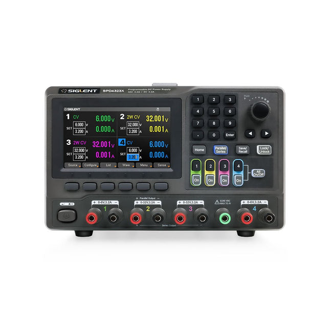
SPD4323X
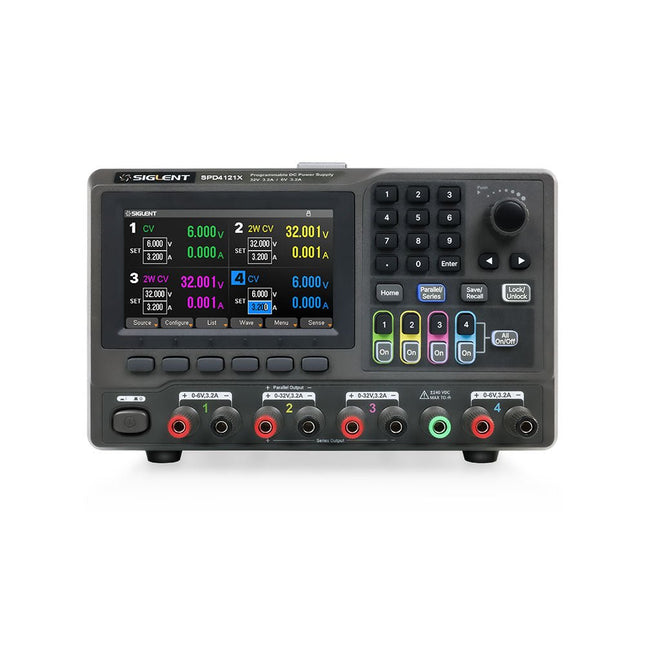
SPD4121X
SPD4306X
Channel Output
CH1: Voltage 0 to 6 V Current 0 to 3.2 ACH2: Voltage 0 to 32 V Current 0 to 3.2 ACH3: Voltage 0 to 32 V Current 0 to 3.2 ACH4: Voltage 0 to 6 V Current 0 to 3.2 A
CH1: Voltage 0 to 15 V Current 0 to 1.5 ACH2: Voltage 0 to 12 V Current 0 to 10 ACH3: Voltage 0 to 12 V Current 0 to 10 ACH4: Voltage 0 to 15 V Current 0 to 1.5 A
CH1: Voltage 0 to 15 V Current 0 to 1.5 ACH2: Voltage 0 to 30 V Current 0 to 6 ACH3: Voltage 0 to 30 V Current 0 to 6 ACH4: Voltage 0 to 15 V Current 0 to 1 A
Resolution
1 mV, 1 mA
1 mV, 1 mA
1 mV, 1 mA
Setting Accuracy
Voltage: ±(0.03% of reading+10) mV, Current: ±(0.3% of reading+10) mA
Voltage: ±(0.03% of reading+10) mV, Current: ±(0.3% of reading+10) mA
Voltage: ±(0.03% of reading+10) mV, Current: ±(0.3% of reading+10) mA
Readback Accuracy
Voltage: ±(0.03% of reading+10) mV, Current: ±(0.3% of reading+10) mA
Voltage: ±(0.03% of reading+10) mV, Current: ±(0.3% of reading+10) mA
Voltage: ±(0.03% of reading+10) mV, Current: ±(0.3% of reading+10) mA
Display
4.3" TFT-LCD 5-digit voltage and current display
4.3" TFT-LCD 5-digit voltage and current display
4.3" TFT-LCD 5-digit voltage and current display
Output power
240 W
285 W
400 W
Lieferumfang
1x Siglent SPD4306X Power Supply
1x Power cord (EU)
1x Output test cord (3 A)
1x USB cable
1x Quick start guide
Downloads
Datasheet
Manual
Quick start
The Siglent SPD4121X is a 4-channel DC Linear Programmable Power Supply equipped with a 4.3-inch TFT-LCD display, friendly human-machine interface, and excellent performance indicators. Real-time waveform display provides engineers with an informative user interface.
SPD4121X offers a total output power of 285 W with a resolution of 1 mV/1 mA. The maximum voltage and current for each channel are as follows:
CH1: 15 V/1.5 A
CH2: 12 V/10 A
CH3: 12 V/10 A
CH4: 15 V/1.5 A
Features
Rated output power: 285 W
Rated voltage: 32 V, 12 V, 30 V
Up to four high-precision power supplies with independent controllable outputs, supporting CH2 and CH3 series and parallel connections
Clear graphical interface with waveform and timer display modes
5-digit voltage and current display with minimum resolution of 1 mV, 1 mA
Fast output response time: <50us
The high current channel support remote voltage compensation sense function. The maximum compensation voltage is 0.6 V
Overvoltage protection and overcurrent protection or safe and accurate operation
Equipped with a 4.3-inch TFT-LCD display (480 x 272 resolution)
USB and LAN standard communication
USB-GPIB module is optional
Excellent channel density with up to 4 channels in a 3U half rack package
Internal data storage for setups and parameters
Embedded Web Server with instrument communication that doesn’t require software installation
Fully SCPI programming command set support as well as a LabView driver for remote control and system automation
Technische Daten
SPD4323X
SPD4121X
SPD4306X
Channel Output
CH1: Voltage 0 to 6 V Current 0 to 3.2 ACH2: Voltage 0 to 32 V Current 0 to 3.2 ACH3: Voltage 0 to 32 V Current 0 to 3.2 ACH4: Voltage 0 to 6 V Current 0 to 3.2 A
CH1: Voltage 0 to 15 V Current 0 to 1.5 ACH2: Voltage 0 to 12 V Current 0 to 10 ACH3: Voltage 0 to 12 V Current 0 to 10 ACH4: Voltage 0 to 15 V Current 0 to 1.5 A
CH1: Voltage 0 to 15 V Current 0 to 1.5 ACH2: Voltage 0 to 30 V Current 0 to 6 ACH3: Voltage 0 to 30 V Current 0 to 6 ACH4: Voltage 0 to 15 V Current 0 to 1 A
Resolution
1 mV, 1 mA
1 mV, 1 mA
1 mV, 1 mA
Setting Accuracy
Voltage: ±(0.03% of reading+10) mV, Current: ±(0.3% of reading+10) mA
Voltage: ±(0.03% of reading+10) mV, Current: ±(0.3% of reading+10) mA
Voltage: ±(0.03% of reading+10) mV, Current: ±(0.3% of reading+10) mA
Readback Accuracy
Voltage: ±(0.03% of reading+10) mV, Current: ±(0.3% of reading+10) mA
Voltage: ±(0.03% of reading+10) mV, Current: ±(0.3% of reading+10) mA
Voltage: ±(0.03% of reading+10) mV, Current: ±(0.3% of reading+10) mA
Display
4.3" TFT-LCD 5-digit voltage and current display
4.3" TFT-LCD 5-digit voltage and current display
4.3" TFT-LCD 5-digit voltage and current display
Output power
240 W
285 W
400 W
Lieferumfang
1x Siglent SPD4121X Power Supply
1x Power cord (EU)
1x Output test cord (3 A)
1x USB cable
1x Quick start guide
Downloads
Datasheet
Manual
Quick start
The Siglent SPD4323X is a 4-channel DC Linear Programmable Power Supply equipped with a 4.3-inch TFT-LCD display, friendly human-machine interface, and excellent performance indicators. Real-time waveform display provides engineers with an informative user interface.
SPD4323X offers a total output power of 240 W with a resolution of 1 mV/1 mA. The maximum voltage and current for each channel are as follows:
CH1: 6 V/3.2 A
CH2: 32 V/3.2 A
CH3: 32 V/3.2 A
CH4: 6 V/3.2 A
Features
Rated output power: 240 W
Rated voltage: 32 V, 12 V, 30 V
Up to four high-precision power supplies with independent controllable outputs, supporting CH2 and CH3 series and parallel connections
Clear graphical interface with waveform and timer display modes
5-digit voltage and current display with minimum resolution of 1 mV, 1 mA
Fast output response time: <50us
The high current channel support remote voltage compensation sense function. The maximum compensation voltage is 0.6 V
Overvoltage protection and overcurrent protection or safe and accurate operation
Equipped with a 4.3-inch TFT-LCD display (480 x 272 resolution)
USB and LAN standard communication
USB-GPIB module is optional
Excellent channel density with up to 4 channels in a 3U half rack package
Internal data storage for setups and parameters
Embedded Web Server with instrument communication that doesn’t require software installation
Fully SCPI programming command set support as well as a LabView driver for remote control and system automation
Technische Daten
SPD4323X
SPD4121X
SPD4306X
Channel Output
CH1: Voltage 0 to 6 V Current 0 to 3.2 ACH2: Voltage 0 to 32 V Current 0 to 3.2 ACH3: Voltage 0 to 32 V Current 0 to 3.2 ACH4: Voltage 0 to 6 V Current 0 to 3.2 A
CH1: Voltage 0 to 15 V Current 0 to 1.5 ACH2: Voltage 0 to 12 V Current 0 to 10 ACH3: Voltage 0 to 12 V Current 0 to 10 ACH4: Voltage 0 to 15 V Current 0 to 1.5 A
CH1: Voltage 0 to 15 V Current 0 to 1.5 ACH2: Voltage 0 to 30 V Current 0 to 6 ACH3: Voltage 0 to 30 V Current 0 to 6 ACH4: Voltage 0 to 15 V Current 0 to 1 A
Resolution
1 mV, 1 mA
1 mV, 1 mA
1 mV, 1 mA
Setting Accuracy
Voltage: ±(0.03% of reading+10) mV, Current: ±(0.3% of reading+10) mA
Voltage: ±(0.03% of reading+10) mV, Current: ±(0.3% of reading+10) mA
Voltage: ±(0.03% of reading+10) mV, Current: ±(0.3% of reading+10) mA
Readback Accuracy
Voltage: ±(0.03% of reading+10) mV, Current: ±(0.3% of reading+10) mA
Voltage: ±(0.03% of reading+10) mV, Current: ±(0.3% of reading+10) mA
Voltage: ±(0.03% of reading+10) mV, Current: ±(0.3% of reading+10) mA
Display
4.3" TFT-LCD 5-digit voltage and current display
4.3" TFT-LCD 5-digit voltage and current display
4.3" TFT-LCD 5-digit voltage and current display
Output power
240 W
285 W
400 W
Lieferumfang
1x Siglent SPD4323X Power Supply
1x Power cord (EU)
1x Output test cord (3 A)
1x USB cable
1x Quick start guide
Downloads
Datasheet
Manual
Quick start
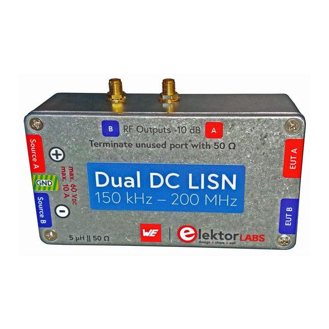
Die Messung der leitungsgebundenen Emission ist die einfachste und kostengünstigste Methode, um einen Hinweis darauf zu erhalten, ob ein Design die EMI/EMV-Anforderungen erfüllen kann. Ein Line Impedance Stabilization Network (LISN) ist dabei ein unverzichtbarer Bestandteil eines EMV-Prüfaufbaus (Pre-Compliance).
In Zusammenarbeit mit Würth Elektronik hat Elektor einen 5 µH, 50 Ω Dual DC LISN entwickelt, der Spannungen bis zu 60 V und Ströme bis zu 10 A unterstützt.
Das Gerät misst HF-Störungen auf beiden Kanälen (der Stromversorgung) mit Hilfe von 5-μH-Sperrinduktivitäten. Das interne 10-dB-Dämpfungsnetzwerk – eines in jedem Kanal – enthält einen Hochpassfilter dritter Ordnung mit einer Grenzfrequenz von 9 kHz, um den Eingang von Instrumenten wie z. B. einem Spektrumanalysator vor potenziell schädlichen Gleichspannungen oder niedrigen Frequenzen zu schützen, die vom Prüfling (EUT – Equipment Under Test) stammen.
Technische Daten
RF-Pfad
Kanäle
2 (mit Klemmdioden)
Bandbreite
150 kHz – 200 MHz
Induktivität
5 μH || 50 Ω
Interne Abschwächung
10 dB
Steckverbinder
SMA
DC-Pfad
Max. Strom
< 10 ADC
Max. Spannung
< 60 VDC
DC-Widerstand
< 2 x 70 mΩ
Platinengröße
94,2 x 57,4 mm
Steckverbinder
4-mm-Bananenstecker
Hammond-Gehäuse
Typ
1590N
Abmessungen
121 x 66 x 40 mm
Lieferumfang
1x 4-lagige Platine mit allen SMD-Bauteilen bestückt
1x Vorgebohrtes Gehäuse mit vorgedrucktem Frontplattenlayout
5x Vergoldete, isolierte 4-mm-Bananenbuchsen, ausgelegt für 24 A, 1 kV
1x Hammond-Gehäuse 1590N1, Aluminium (Druckgusslegierung)
Mehr Info
Projekt auf Elektor Labs: Dual DC LISN for EMC pre-compliance testing
Elektor 9-10/2021: EMV-Vor-Konformitätstester für Ihr Projekt mit DC-Versorgung (Teil 1)
Elektor 11-12/2021: EMV-Vorkonformitätstest für Ihr DC-versorgtes Projekt (Teil 2)
The FRDM-MCXN947 is a compact and versatile development board designed for rapid prototyping with MCX N94 and N54 microcontrollers. It features industry-standard headers for easy access to the MCU's I/Os, integrated open-standard serial interfaces, external flash memory, and an onboard MCU-Link debugger.
Technische Daten
Microcontroller
MCX-N947 Dual Arm Cortex-M33 cores @ 150 MHz each with optimized performance efficiency, up to 2 MB dual-bank flash with optional full ECC RAM, External flash
Accelerators: Neural Processing Unit, PowerQuad, Smart DMA, etc.
Memory Expansion
*DNP Micro SD card socket
Connectivity
Ethernet Phy and connector
HS USB-C connectors
SPI/I²C/UART connector (PMOD/mikroBUS, DNP)
WiFi connector (PMOD/mikroBUS, DNP)
CAN-FD transceiver
Debug
On-board MCU-Link debugger with CMSIS-DAP
JTAG/SWD connector
Sensor
P3T1755 I³C/I²C Temp Sensor, Touch Pad
Expansion Options
Arduino Header (with FRDM expansion rows)
FRDM Header
FlexIO/LCD Header
SmartDMA/Camera Header
Pmod *DNP
mikroBUS
User Interface
RGB user LED, plus Reset, ISP, Wakeup buttons
Lieferumfang
1x FRDM-MCXN947 Development Board
1x USB-C Cable
1x Quick Start Guide
Downloads
Datasheet
Block diagram