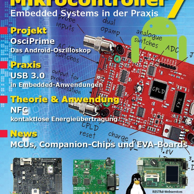
Inhalt:
Praxis
JellyScope – Open Source Android-Oszilloskop
HDMI to VGA – USB-gespeister DVI/HDMI-zu-VGA-Wandler mit Audio-Extraction
WEB-ArByter – Mit dem PicosG20 Embedded-Projekte per Smartphone steuern
Aufsicht – USB-2.0 und 3.0 Port-Monitor mit MSP430
Nimm Zwei – Doppel-USB-Stromversorgung
Know-how
Gib dem Panda Android – Linaro Android auf dem PandaBoard installieren
Leinen los – Drahtlose Ladestation Qi-konform entwickeln
Info
Prêt-à-porter – Marktübersicht Embedded-CPU-Module
Der bessere Flash-Speicher – FRAM: Funktion, Qualität und Zuverlässigkeit
Transit-Chip – LPC-800: 32-Bit-ARM im 8-Bit-Gewand
Don't touch – E-Feld-basierte Gestensteuerung
Aktuell – MCUs, Companion-Chips, Eva-Boards und Tools
Weitere Hefte aus dieser Reihe:
Mikrocontroller 6 (PDF)
Mikrocontroller 5 (PDF)
Mikrocontroller 4 (PDF)
Mikrocontroller 3 (PDF)
Mikrocontroller 2 (PDF)
Mikrocontroller 1 (PDF)
Realize your own projects with the Elektor Arduino Nano MCCAB Training Board
The microcontroller is probably the most fascinating subfield of electronics. Due to the multitude of functions, it combines on its chip, it is a universal multi-tool for developers to realize their projects. Practically every device of daily use today is controlled by a microcontroller. However, for an electronic layman, realizing his own ideas with a microcontroller has so far remained a pipe dream due to its complexity. The Arduino concept has largely simplified the use of microcontrollers, so that now even laymen can realize their own electronics ideas with a microcontroller.
Book & Hardware in the Bundle: 'Learning by Doing'
This book, which is included in the bundle, shows how you can realize your own projects with a microcontroller even without much experience in electronics and programming languages. It is a microcontrollers hands-on course for starters, because after an overview of the internals of the microcontroller and an introduction to the programming language C, the focus of the course is on the practical exercises. The reader acquires the necessary knowledge by 'learning by doing': in the extensive practical section with 12 projects and 46 exercises, what is learned in the front part of the book is underpinned with many examples. The exercises are structured in such a way that the user is given a task to solve using the knowledge built up in the theoretical part of the book. Each exercise is followed by a sample solution that is explained and commented on in detail, which helps the user to solve problems and compare it with his own solution.
Arduino IDE
The Arduino IDE is a software development environment that can be downloaded for free to your own PC and that contains the entire software package needed for your own microcontroller projects. You write your programs ('apps') with the IDE’s editor in the C programming language. You translate them into the bits and bytes that the microcontroller understands using the Arduino IDE's built-in compiler, and then load them into the microcontroller's memory on the Elektor Arduino MCCAB Nano Training Board via a USB cable.
Query or control external sensors, motors or assemblies
In addition to an Arduino Nano microcontroller module, the Elektor Arduino Nano MCCAB Training Board contains all the components required for the exercises, such as light-emitting diodes, switches, pushbuttons, acoustic signal transmitters, etc. External sensors, motors or assemblies can also be queried or controlled with this microcontroller training system.
Specifications (Arduino Nano MCCAB Training Board)
Power Supply
Via the USB connection of the connected PC or an external power supply unit (not included)
Operating Voltage
+5 Vcc
Input Voltage
All inputs
0 V to +5 V
VX1 and VX2
+8 V to +12 V (only when using an external power supply)
Hardware periphery
LCD
2x16 characters
Potentiometer P1 & P2
JP3: selection of operating voltage of P1 & P2
Distributor
SV4: Distributor for the operating voltagesSV5, SV6: Distributor for the inputs/outputs of the microcontroller
Switches and buttons
RESET button on the Arduino Nano module 6x pushbutton switches K1 ... K6 6x slide switches S1 ... S6 JP2: Connection of the switches with the inputs of the microcontroller
Buzzer
Piezo buzzer Buzzer1 with jumper on JP6
Indicator lights
11 x LED: Status indicator for the inputs/outputs LED L on the Arduino Nano module, connected to GPIO D13 JP6: Connection of LEDs LD10 ... LD20 with GPIOs D2 ... D12
Serial interfacesSPI & I²C
JP4: Selection of the signal at pin X of the SPI connector SV12 SV9 to SV12: SPI interface (3.3 V/5 V) or I²C interface
Switching output for external devices
SV1, SV7: Switching output (maximum +24 V/160 mA, externally supplied) SV2: 2x13 pins for connection of external modules
3x3 LED matrix(9 red LEDs)
SV3: Columns of the 3x3 LED matrix (outputs D6 ... D8) JP1: Connection of the rows with the GPIOs D3 ... D5
Software
Library MCCABLib
Control of hardware components (switches, buttons, LEDs, 3x3 LED matrix, buzzer) on the MCCAB Training Board
Operating Temperature
Up to +40 °C
Dimensions
100 x 100 x 20 mm
Specifications (Arduino Nano)
Microcontroller
ATmega328P
Architecture
AVR
Operating Voltage
5 V
Flash Memory
32 KB, of which 2 KB used by bootloader
SRAM
2 KB
Clock Speed
16 MHz
Analog IN Pins
8
EEPROM
1 KB
DC Current per I/O Pins
40 mA on one I/O pin, total maximum 200 mA on all pins together
Input Voltage
7-12 V
Digital I/O Pins
22 (6 of which are PWM)
PWM Output
6
Power Consumption
19 mA
Dimensions
18 x 45 mm
Weight
7 g
Included
Elektor Arduino Nano MCCAB Training Board
Arduino Nano
Book: Microcontrollers Hands-on Course for Arduino Starters
KOCHSHOW À LA ELEKTOR LORA MIT DEM RASPBERRY PI PICOViel Spaß mit MicroPython! WAS IST RISC-V?Warum die Industrie einen neuen Prozessorkern so spannend findet 60 JAHRE ELEKTORSommer-Projekte VIELSEITIGE SPANNUNGSVERSORGUNG FÜR BREADBOARDSPositive und negative 5-V-Ausgangsspannungen von USB RASPBERRY PI PICO ESSENTIALSEin Beispiel-Kapitel: WLAN mit dem Raspberry Pi Pico MAGNETISCHE LEVITATION AUF DIE EINFACHE ART PARALLAX PROPELLER 2Teil 3: Smart Pins und serielle Daten (UART) NUCLEO-BOARDS PROGRAMMIEREN MIT DER STM32CUBE-IDEEin Beispiel-Kapitel: FreeRTOS für die STM32 MCU VON ENTWICKLERN FÜR ENTWICKLERTipps & Tricks, Best Practice und andere nützliche Infos DIGITALE PINZETTE MINIWARE DT71 WEARABLE-WLAN GADGETESPHome wieder im Einsatz! ALLER ANFANG …muss nicht schwer sein! EINFACHE SKETCHES MIT DEM QWIIC-ÖKOSYSTEM JAVA AUF DEM RASPBERRY PITeil 2: Steuerung von GPIOs mit einem Spring-REST-Service RASPBERRY PI COMPUTE MODULE 4Ein Raspberry Pi für die Industrie PORTABLES AUTONOMES FEINSTAUBMESSGERÄT FÜR 2,5-ΜM-PARTIKELBehalten Sie Ihre Gesundheit im Auge AUS DER LEBEN GEGRIFFENDie Zukunft war in der Vergangenheit besser MICROPYTHON FÜR DEN ESP32 UND CO.Teil 1: Installation und erste Programme LADUNGSGEKOPPELTE BAUTEILE IN OSZILLOSKOPENBemerkenswerte Bauteile ESD – DER UNSICHTBARE BLITZZerfetzt Halbleiter wie ein Blitz einen Baum SOLARANLAGE FÜR MÄHROBOTERÖkologisch - preiswert - einfach! EUROPAS BEMÜHUNGEN, BIG TECH ZU ZÄHMEN HEXADOKUThe Original Elektorized Sudoku
The Elektor LoRa NodeVersatile, long-range, 868-MHz remote control with state feedback and STM32 Inside
InteractiveCorrections & Updates || Questions & Answers
Analogue Electronics DesignCase Study #1 — Section 2: Preamplifier optimized for MEMS microphone
My IoT Button: A Button for the WebPart 1: IoT architecture
BASIC for the ESP32 and ESP8266Programming with Annex WiFi RDS
ESP32 Doorbell via Telegram“The UPS Man Always Rings Once”
Small Circuits RevivalCapita Selecta from the Elektor Project Suggestions Box
My First LoRaWANWith Blue Pill, LoRa Breakout Board and The Things Network
Elektor Connexions 2003EL
“A Strong Supporter of Open Internet”Interview with Wienke Giezeman, Initiator of The Things Network
The Meadow F7 BoardA great board for .NET developers
Practical ESP32 Multitasking (2)Task priorities
Sigfox and the IoT (3)First steps on the network
Raspberry Pi Bash Command Cheat Sheet
Europe's Most Successful Start-up Accelerator?HighTechXL, Eindhoven, The Netherlands
Review: The Enviro+ RPi-HATMeasure air quality with a Raspberry Pi and the Enviro+ HAT
Steeped in Electronicsordering components from Ukraine and Russia
Review: Andonstar AD407Better than its predecessor?
Lab, Sweet LabA glimpse of The Holy Place — no unauthorized entry.
Optical Probe for OscilloscopesMeasure brightness fluctuations of lighting systems
The 'TABULA' Project - An UpdateTangibles with user feedback
How-To Calculate the Prospective Short-Circuit Current or PSCCand choose the proper circuit breaker
TMS1000 Series Microcontrollers
Peculiar Parts, the series
Starting Out in Electronics (2)
Easier than imagined!
Developer's ZoneTips & Tricks, Best Practices and Other Useful Information
Locating Wayward Wires
Track and trace concealed and defective cables with ease and certainty
Review: Joy-IT DMSO2D72 Portable 3-in-1 Oscilloscope
Homebrew PC for the Electronics LabTips on Component Choice and Construction
The Elektor ‘Intelekt’ Chess Computer (1981)Tiny Chess 86 ported to the Intel 8088
Beyond ElectronicsPCB Art - Pushing the Limits of Industrial Manufacturing
All-in-One-Plattform für KI-Lernen und -Entwicklung im Bereich Edge Intelligence
Dieses auf dem NVIDIA Jetson Orin Nano basierende KI-Starter-Kit ist eine vielseitige Plattform für Lernen, Entwicklung und praktische Experimente im Bereich Edge AI.
Das für den Einsatz mit dem NVIDIA Jetson Orin Nano konzipierte Kit kombiniert ein 11,6-Zoll-IPS-Display, eine schwenk- und neigbare 8-Megapixel-Kamera sowie ein KI-gestütztes Sprachinteraktionssystem.
Es umfasst 30 Funktionsmodule und 38 sorgfältig ausgearbeitete Python-Kurse, die vom Anfänger- bis zum Fortgeschrittenenniveau reichen. Die Kursinhalte decken Python-Grundlagen, Sensortechnologie, KI-basierte Bildverarbeitung (AI Vision) und Objekterkennung ab.
Dank praktischer Schritt-für-Schritt-Übungen – von der grundlegenden Programmierung bis hin zu praxisnahen Computer-Vision-Anwendungen – bietet dieses Kit eine ideale Plattform für Schüler, Maker, Entwickler und alle, die sich mit künstlicher Intelligenz und Edge Computing beschäftigen möchten.
Hinweis: Der NVIDIA Jetson Orin Nano ist nicht im Lieferumfang enthalten.
Features
Entwickelt für den NVIDIA Jetson Orin Nano
KI-Sprachinteraktionsmodul
8-MP-Kamera mit Schwenk-Neige-Steuerung
Unterstützt Objekt- und Gesichtserkennung (Tracking)
Kein Löten oder aufwendige Verkabelung erforderlich
Integriertes 11,6-Zoll-IPS-Display
30 Funktionsmodule
38 Schritt-für-Schritt-Python-Lektionen
Erweiterungsschnittstellen für I²C, UART und GPIO
Tragetasche im Lieferumfang enthalten
Technische Daten
Hauptprozessor
Jetson Orin Nano
Anzahl der Sensoren
30
Design des Sensor-Boards
Integriertes Sensor-Board; kein Löten oder aufwendige Verkabelung erforderlich
Bildschirm
11,6-Zoll-IPS-Bildschirm
Bildschirmauflösung
1366 x 768
Kamera
IMX219 8 MP
Erweiterungsschnittstellen
2x I²C, 1x UART, 1x IO D13, 1x IO D12
Programmierumgebung
Python-basiert
Anzahl der Tutorials
38 kreative Tutorials
Zielgruppe
Schüler, Lehrkräfte, Hardware-Enthusiasten
Anwendungsszenarien
Ideal zum Erlernen der KI-Programmierung und der Grundlagen des Jetson Orin Nano
Abmessungen
300 x 200 x 100 mm
Modulliste
Modul
Anzahl
Temperatur- und Feuchtigkeitssensor
1 Stk.
Taster
4 Stk.
Ultraschall-Abstandssensor
1 Stk.
Lichtsensor
1 Stk.
Linear-Potentiometer
1 Stk.
Summer
1 Stk.
LCD
1 Stk.
Infrarot-Fernbedienung
1 Stk.
Relais
1 Stk.
NFC
1 Stk.
PIR-Bewegungssensor
1 Stk.
Joystick
1 Stk.
4-stelliges Display
1 Stk.
LED
1 Stk.
Mikrofon
1 Stk.
Lautsprecher
1 Paar
Vibrationsmotor
1 Stk.
Berührungssensor
1 Stk.
8x8-RGB-Matrix
1 Stk.
Luftdrucksensor
1 Stk.
Neigungsschalter
1 Stk.
Schrittmotor
1 Stk.
Beschleunigungs- und Gyroskopsensor
1 Stk.
Gassensor (MQ2)
1 Stk.
Hall-Sensor
1 Stk.
Drehgeber (Rotary Encoder)
1 Stk.
Gabellichtschranke
1 Stk.
NTC
1 Stk.
Servo
2 Stk.
Monokulare Kamera
1 Stk.
Lieferumfang
1x Elecrow AI Starter Kit für Jetson Orin Nano
1x IR-Fernbedienung
1x NFC-Karte
1x 128 GB SD-Karte
1x 40-Pin-GPIO-Kabel
2x 22-Pin-FPC-Kabel
2x 24-Pin-FPC-Kabel
1x Jetson-DP- und USB-Adapterplatine
Nicht enthalten
NVIDIA Jetson Orin Nano
Downloads
Manual
Wiki
OpenClaw Install and Config Guide
Practical Low-Cost Methods for Reliable PCB Production
This book explains how to carry out reliable SMD assembly using affordable tools and small-scale equipment. It follows the complete workflow step by step, including tool selection, solder paste handling, stencil use, component placement, reflow methods, inspection, and rework.
The focus is on bench-level and small-lab production rather than industrial assembly lines. It shows practical methods for building single and double-sided SMD boards with repeatable results.
Topics include solder paste and flux, temperature profiles, hot air and hotplate techniques, small reflow ovens, inspection methods, and defect correction. Checklists and example workflows are included to help reduce errors and improve consistency.
Key features:
Tools and supplies for SMD assembly and rework
Solder paste types, storage, and handling
Stencils and paste application methods
Pick and place workflow and component orientation
Temperature profiles and reflow methods
Hot air, hotplate, and reflow oven processes
Inspection and quality control
Common defects such as tombstoning and solder bridges
Practical rework and component replacement
Bench-level professional workflows and checklists
This book is designed as a practical bench reference for anyone who wants to assemble and troubleshoot their own SMD boards with reliable results.
Hochleistungsfähiges LoRa-Kommunikationsgerät
Das Elecrow ThinkNode M5 ist ein kompaktes, tragbares LoRa-Kommunikationsgerät, das für netzunabhängige Nachrichtenübermittlung, Standortfreigabe und den Außeneinsatz konzipiert wurde. Ausgestattet mit einem ESP32-S3-Prozessor und einem SX1262-LoRa-Chip, wird es mit vorinstallierter Meshtastic-Firmware geliefert und lässt sich bequem per Bluetooth über die offizielle Meshtastic-App konfigurieren.
Das integrierte Multi-GNSS-Modul unterstützt GPS, GLONASS, BeiDou und QZSS für eine zuverlässige Positionsbestimmung und Standortfreigabe. Nachrichten und Geräteinformationen werden auf dem energieeffizienten 1,54-Zoll-E-Paper-Display angezeigt, während der integrierte 1.200-mAh-Akku einen langen mobilen Betrieb ermöglicht.
Dank der integrierten LoRa-Antenne, des kompakten Gehäuses, der Echtzeituhr (RTC) und der Unterstützung für Meshtastic- sowie MeshCore-Firmware ist das ThinkNode M5 eine praktische Kommunikationslösung für Wandern, Camping, abgelegene Gebiete und Notfallsituationen, in denen keine herkömmlichen Mobilfunknetze verfügbar sind.
Features
LoRa-Kommunikation
Multi-GNSS-Positionsbestimmung
1.200-mAh-Akku
1,54" E-Paper-Display
Integrierte RTC
Kompatibel mit MeshCore
Kompatibel mit Meshtastic
Technische Daten
Hauptprozessor (ESP32-S3)
CPU/SoC
Xtensa 32-Bit-LX7-Dual-Core-Prozessor, getaktet mit bis zu 240 MHz
Systemspeicher
512 KB SRAM, 8 MB PSRAM
Speicher
4 MB Flash, 384 KB ROM
Firmware
Meshtastic-Firmware ist voll kompatibel; Signalübertragung im LoRa-Modus
EPD (Electronic Paper Display)
Displaygröße
1,54-Zoll-EPD (monochromer E-Ink-Bildschirm)
Displaymaterial
E-Ink (Electronic Ink)
Auflösung
200 x 200
Treiber-Chip
SSD1681 (über SPI- oder I²C-Schnittstelle)
Zeit für vollständige Aktualisierung
2 s
Drahtlose Kommunikation
Bluetooth
Bluetooth Low Energy und Bluetooth 5.0 (Konfiguration per Smartphone)
LoRa
SX1262 LoRa-Modul, EU 868 MHz (externe Antenne)
Hardware
Schnittstellen
USB-C, RP-SMA
Funktionen
GPS-Ortung (GPS, GLONASS, BeiDou, QZSS), EPD-Display, RTC, USB 2.0, PMU-Energiemanagement (integrierter 1200-mAh-Lithium-Akku), Summer usw.
Tasten
Drehschalter, Funktionstaste, Blättertaste, GPS-Schalter, Reset-Taste
LED-Anzeige
Stromversorgung, GPS/LoRa-Anzeige
Sonstiges
Spannungsversorgung
5 V/1 A; unterstützt Stromversorgung über USB oder Lithium-Akku
Stromverbrauch
Maximaler Betriebsstrom ca. 340 mA (CPU + LoRa-Modul); Stromverbrauch im Energiesparmodus ca. 34 µA
Betriebstemperatur
-10 bis 50°C
Lagertemperatur
-20 bis 60°C
Relative Luftfeuchtigkeit
10–95% bei 40°C (nicht kondensierend)
Gehäuse
ABS-Kunststoff
Abmessungen
82 x 51,6 x 26,3 mm
Gewicht
81 g
Lieferumfang
1x Elecrow ThinkNode M5
1x LoRa-Antenne
1x USB-C Kabel
1x Manual
Downloads
Manual
ARM Cortex-M Embedded Design from 0 to 1
Hobbyists can mash together amazing functional systems using platforms like Arduino or Raspberry Pi, but it is imperative that engineers and product designers understand the foundational knowledge of embedded design. There are very few resources available that describe the thinking, strategies, and processes to take an idea through hardware design and low-level driver development, and successfully build a complete embedded system. Many engineers end up learning the hard way, or never really learn at all.
ARM processors are essentially ubiquitous in embedded systems. Design engineers building novel devices must understand the fundamentals of these systems and be able to break down large, complicated ideas into manageable pieces. Successful product development means traversing a huge amount of documentation to understand how to accomplish what you need, then put everything together to create a robust system that will reliably operate and be maintainable for years to come.
This book is a case study in embedded design including discussion of the hardware, processor initialization, low‑level driver development, and application interface design for a product. Though we describe this through a specific application of a Cortex-M3 development board, our mission is to help the reader build foundational skills critical to being an excellent product developer. The completed development board is available to maximize the impact of this book, and the working platform that you create can then be used as a base for further development and learning.
The Embedded in Embedded program is about teaching fundamental skill sets to help engineers build a solid foundation of knowledge that can be applied in any design environment. With nearly 20 years of experience in the industry, the author communicates the critical skill development that is demanded by companies and essential to successful design. This book is as much about building a great design process, critical thinking, and even social considerations important to developers as it is about technical hardware and firmware design.
Downloads
EiE Software Archive (200 MB)
IAR ARM 8.10.1 (Recommended IDE version to use) (1.2 GB)
IAR ARM 7.20.1 (Optional IDE version to use) (600 MB)
Mit diesem 65 W USB-C PD Netzteil (mit GaN-Technologie) können Sie den FNIRSI HS-01 Lötkolben sofort verwenden. Natürlich können Sie mit diesem Charger auch Ihre Tablets und Smartphones über USB-C und USB-A schnell aufladen.
Lieferumfang
65 W USB-C PD GaN Netzteil (EU)
Dieses Bundle enthält das Red Pitaya STEMlab 125-14 PRO Gen 2 Starter Kit und das neue Buch "Experimenting with Red Pitaya STEMlab Gen 2".
Das Red Pitaya STEMlab 125-14 PRO Gen 2 Starter Kit ist eine leistungsstarke und flexible Plattform für Signalverarbeitung, Datenerfassung und elektronische Messanwendungen. Dieses Kit wurde für Ingenieure, Entwickler, Forscher und Dozenten konzipiert und bietet alles, was für den Einstieg in die Entwicklung fortschrittlicher Mess- und Steuerungssysteme erforderlich ist.
Das Herzstück des Kits ist das STEMlab 125-14 PRO Gen 2-Board, eine verbesserte und ultraleichte Entwicklungsplatine. Angetrieben vom Xilinx Zynq-7010 SoC mit 512 MB RAM kombiniert es die Programmierbarkeit eines FPGAs mit der Rechenleistung eines ARM-Prozessors, um leistungsstarke Messtechnik und kundenspezifische Signalverarbeitungslösungen zu ermöglichen.
Das Board bietet eine 14-Bit-ADC- und DAC-Auflösung, eine Abtastrate von 125 MS/s, einen Eingangsbereich von ±20 V und eine Bandbreite von bis zu 60 MHz. Dank seines verbesserten rauscharmen analogen Frontends, der USB-C-Konnektivität und des kompakten Designs eignet es sich für anspruchsvolle Anwendungen wie HF-Entwicklung, Radarsysteme, Photonikforschung, Software-Defined Radio (SDR) und industrielle Automatisierung.
Das Starter Kit enthält alles notwendige Zubehör für den sofortigen Einsatz: eine microSD-Karte mit vorinstalliertem Betriebssystem, ein Netzteil, ein Ethernet-Kabel für den Fernzugriff, zwei 100-MHz-Oszilloskop-Messspitzen sowie SMA-zu-BNC-Adapter für flexible Signalanschlüsse.
Das Red Pitaya STEMlab 125-14 PRO Gen 2 Starter Kit ist eine hervorragende Plattform für Rapid Prototyping, FPGA-Entwicklung, Messtechnik und fortgeschrittene Elektronikversuche.
Features
14-Bit-ADC- und DAC-Auflösung
Abtastrate: 125 MS/s
Eingangsspannungsbereich: ±20 V
Bandbreite: Bis zu 60 MHz
Xilinx Zynq-7010 SoC (FPGA + ARM-Prozessor)
512 MB RAM
Rauscharme analoge Front- und Backends
Anwendungen
HF-Entwicklung und -Test
Radar- und drahtlose Systeme
Software Defined Radio (SDR)
Photonik und optische Forschung
Industrielle Automatisierungs- und Steuerungssysteme
Signalanalyse und -instrumentierung
Schnelles Prototyping elektronischer Bauteile Messsysteme
Technische Daten
Prozessor
Dual-Core ARM Cortex-A9
FPGA
AMD Xilinx Zynq-7010 SoC
RAM
512 MB (4 Gb)
Speicher
microSD-Karte (bis zu 32 GB)
Betriebssystem
Linux-basiertes Red Pitaya OS
ADC-Auflösung
14 Bit
DAC Auflösung
14 Bit
Bandbreite
60 MHz (DC)
Abtastrate
125 MS/s
Analoge Eingangskanäle
2
Analoge Ausgangskanäle
2
Eingangsspannungsbereich
±1 V (LV) / ±20 V (HV)
Eingangsimpedanz
1 MΩ / 10 pF
Ausgangsspannungsbereich
±1 V
Ethernet
1x Gigabit Ethernet (RJ45)
USB
2x USB-C 2.0 (für Stromversorgung und Konsole)
Digitale Ein-/Ausgänge
16x GPIO (3,3 V)
Kommunikationsschnittstellen
I²C, SPI, UART, CAN
Stromversorgung
5 V/3 A über USB-C
Abmessungen
106,8 x 60,0 x 17,9 mm
Lieferumfang
1x Red Pitaya STEMlab 125-14 PRO Gen 2 Board
2x 100-MHz-Oszilloskop-Tastköpfe
2x SMA-zu-BNC-Adapter
1x microSD-Karte mit vorinstalliertem Betriebssystem
1x USB-C-Netzteil
1x Ethernet-Kabel
Downloads
Documentation
Schematics
Buch: Experimenting with Red Pitaya STEMlab Gen 2
Mit diesem neuen Buch geht Red Pitaya über ein vielseitiges Board hinaus – es wird zu einem leistungsstarken Laborinstrument für präzise Messungen, Analysen und Steuerungen.
Von den Grundlagen der Entwicklung elektronischer Projekte über Überwachung, Regelung und Design bis hin zu Tests führt Sie dieses Buch Schritt für Schritt durch alles, was Sie wissen müssen, um das volle Potenzial der Red Pitaya-Hardware und -Software auszuschöpfen.
Das Buch stellt Echtzeitprojekte auf FPGA-Basis vor, die auf einem PC mit der Vivado-Umgebung entwickelt und anschließend zur Ausführung und zum Testen auf die Red Pitaya übertragen werden.
Sie lernen mehr über gesteigerte Leistung, erweiterte I/O-Möglichkeiten, verbesserte FPGA-Funktionen sowie fortschrittliche Konnektivitätsoptionen, die neue Möglichkeiten für präzise Messungen, Überwachung und Steuerung in Ihren Embedded-Anwendungen eröffnen.
Im Buch entdecken Sie:
Einen tiefgehenden Einblick in die Red Pitaya-Architektur und das Hardware-Design
Elektronische Experimente mit Red Pitaya für Mess- und Überwachungsanwendungen
Praxisnahe Projekte mit der Programmiersprache Python
Praktische Anleitungen zur FPGA-Programmierung mit Red Pitaya
Red Pitaya FPGA-Projekte mit Verilog HDL in der Vivado IDE
Die praxisorientierte Entwicklung elektronischer Projekte inklusive Messung und Tests
Schritt-für-Schritt-Beispiele, die Theorie und reale Umsetzung miteinander verbinden
Ganz gleich, ob Sie eigene elektronische Schaltungen entwerfen, Werkzeuge zur Signalanalyse entwickeln oder Echtzeit-Steuerungs- und Überwachungssysteme erstellen – dieses Buch vermittelt Ihnen das nötige Wissen und die Sicherheit, um die Red Pitaya-Plattform vollständig zu verstehen und individuell anzupassen.
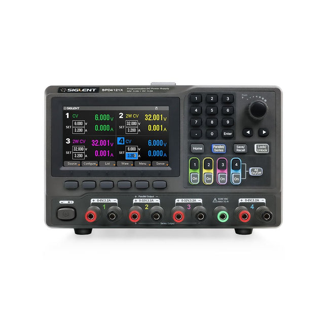
The Siglent SPD4121X is a 4-channel DC Linear Programmable Power Supply equipped with a 4.3-inch TFT-LCD display, friendly human-machine interface, and excellent performance indicators. Real-time waveform display provides engineers with an informative user interface.
SPD4121X offers a total output power of 285 W with a resolution of 1 mV/1 mA. The maximum voltage and current for each channel are as follows:
CH1: 15 V/1.5 A
CH2: 12 V/10 A
CH3: 12 V/10 A
CH4: 15 V/1.5 A
Features
Rated output power: 285 W
Rated voltage: 32 V, 12 V, 30 V
Up to four high-precision power supplies with independent controllable outputs, supporting CH2 and CH3 series and parallel connections
Clear graphical interface with waveform and timer display modes
5-digit voltage and current display with minimum resolution of 1 mV, 1 mA
Fast output response time: <50us
The high current channel support remote voltage compensation sense function. The maximum compensation voltage is 0.6 V
Overvoltage protection and overcurrent protection or safe and accurate operation
Equipped with a 4.3-inch TFT-LCD display (480 x 272 resolution)
USB and LAN standard communication
USB-GPIB module is optional
Excellent channel density with up to 4 channels in a 3U half rack package
Internal data storage for setups and parameters
Embedded Web Server with instrument communication that doesn’t require software installation
Fully SCPI programming command set support as well as a LabView driver for remote control and system automation
Technische Daten
SPD4323X
SPD4121X
SPD4306X
Channel Output
CH1: Voltage 0 to 6 V Current 0 to 3.2 ACH2: Voltage 0 to 32 V Current 0 to 3.2 ACH3: Voltage 0 to 32 V Current 0 to 3.2 ACH4: Voltage 0 to 6 V Current 0 to 3.2 A
CH1: Voltage 0 to 15 V Current 0 to 1.5 ACH2: Voltage 0 to 12 V Current 0 to 10 ACH3: Voltage 0 to 12 V Current 0 to 10 ACH4: Voltage 0 to 15 V Current 0 to 1.5 A
CH1: Voltage 0 to 15 V Current 0 to 1.5 ACH2: Voltage 0 to 30 V Current 0 to 6 ACH3: Voltage 0 to 30 V Current 0 to 6 ACH4: Voltage 0 to 15 V Current 0 to 1 A
Resolution
1 mV, 1 mA
1 mV, 1 mA
1 mV, 1 mA
Setting Accuracy
Voltage: ±(0.03% of reading+10) mV, Current: ±(0.3% of reading+10) mA
Voltage: ±(0.03% of reading+10) mV, Current: ±(0.3% of reading+10) mA
Voltage: ±(0.03% of reading+10) mV, Current: ±(0.3% of reading+10) mA
Readback Accuracy
Voltage: ±(0.03% of reading+10) mV, Current: ±(0.3% of reading+10) mA
Voltage: ±(0.03% of reading+10) mV, Current: ±(0.3% of reading+10) mA
Voltage: ±(0.03% of reading+10) mV, Current: ±(0.3% of reading+10) mA
Display
4.3" TFT-LCD 5-digit voltage and current display
4.3" TFT-LCD 5-digit voltage and current display
4.3" TFT-LCD 5-digit voltage and current display
Output power
240 W
285 W
400 W
Lieferumfang
1x Siglent SPD4121X Power Supply
1x Power cord (EU)
1x Output test cord (3 A)
1x USB cable
1x Quick start guide
Downloads
Datasheet
Manual
Quick start
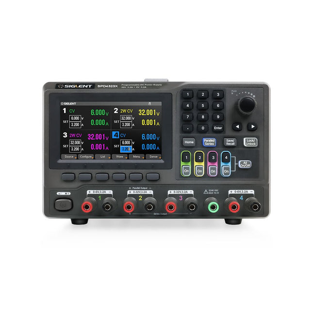
The Siglent SPD4323X is a 4-channel DC Linear Programmable Power Supply equipped with a 4.3-inch TFT-LCD display, friendly human-machine interface, and excellent performance indicators. Real-time waveform display provides engineers with an informative user interface.
SPD4323X offers a total output power of 240 W with a resolution of 1 mV/1 mA. The maximum voltage and current for each channel are as follows:
CH1: 6 V/3.2 A
CH2: 32 V/3.2 A
CH3: 32 V/3.2 A
CH4: 6 V/3.2 A
Features
Rated output power: 240 W
Rated voltage: 32 V, 12 V, 30 V
Up to four high-precision power supplies with independent controllable outputs, supporting CH2 and CH3 series and parallel connections
Clear graphical interface with waveform and timer display modes
5-digit voltage and current display with minimum resolution of 1 mV, 1 mA
Fast output response time: <50us
The high current channel support remote voltage compensation sense function. The maximum compensation voltage is 0.6 V
Overvoltage protection and overcurrent protection or safe and accurate operation
Equipped with a 4.3-inch TFT-LCD display (480 x 272 resolution)
USB and LAN standard communication
USB-GPIB module is optional
Excellent channel density with up to 4 channels in a 3U half rack package
Internal data storage for setups and parameters
Embedded Web Server with instrument communication that doesn’t require software installation
Fully SCPI programming command set support as well as a LabView driver for remote control and system automation
Technische Daten
SPD4323X
SPD4121X
SPD4306X
Channel Output
CH1: Voltage 0 to 6 V Current 0 to 3.2 ACH2: Voltage 0 to 32 V Current 0 to 3.2 ACH3: Voltage 0 to 32 V Current 0 to 3.2 ACH4: Voltage 0 to 6 V Current 0 to 3.2 A
CH1: Voltage 0 to 15 V Current 0 to 1.5 ACH2: Voltage 0 to 12 V Current 0 to 10 ACH3: Voltage 0 to 12 V Current 0 to 10 ACH4: Voltage 0 to 15 V Current 0 to 1.5 A
CH1: Voltage 0 to 15 V Current 0 to 1.5 ACH2: Voltage 0 to 30 V Current 0 to 6 ACH3: Voltage 0 to 30 V Current 0 to 6 ACH4: Voltage 0 to 15 V Current 0 to 1 A
Resolution
1 mV, 1 mA
1 mV, 1 mA
1 mV, 1 mA
Setting Accuracy
Voltage: ±(0.03% of reading+10) mV, Current: ±(0.3% of reading+10) mA
Voltage: ±(0.03% of reading+10) mV, Current: ±(0.3% of reading+10) mA
Voltage: ±(0.03% of reading+10) mV, Current: ±(0.3% of reading+10) mA
Readback Accuracy
Voltage: ±(0.03% of reading+10) mV, Current: ±(0.3% of reading+10) mA
Voltage: ±(0.03% of reading+10) mV, Current: ±(0.3% of reading+10) mA
Voltage: ±(0.03% of reading+10) mV, Current: ±(0.3% of reading+10) mA
Display
4.3" TFT-LCD 5-digit voltage and current display
4.3" TFT-LCD 5-digit voltage and current display
4.3" TFT-LCD 5-digit voltage and current display
Output power
240 W
285 W
400 W
Lieferumfang
1x Siglent SPD4323X Power Supply
1x Power cord (EU)
1x Output test cord (3 A)
1x USB cable
1x Quick start guide
Downloads
Datasheet
Manual
Quick start