
Suchergebnisse für "elektor OR archive OR 1970 OR 2020 OR usb OR stick OR de"
-
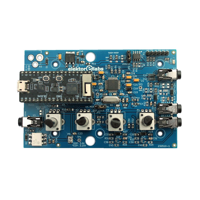
Elektor Labs Elektor Audio DSP FX Processor (Neue Revision)
Der Elektor Audio DSP FX Processor kombiniert einen ESP32-Mikrocontroller und einen ADAU1701 Audio DSP von Analog Devices. Neben einem vom Benutzer programmierbaren DSP-Kern verfügt der ADAU1701 über hochwertige integrierte Analog-Digital- und Digital-Analog-Wandler und verfügt über einen I²S-Port. Dadurch eignet es sich als hochwertiges Audio-Interface für den ESP32. Programme für den ESP32 können mit Arduino, Platform IO, CMake oder durch die Verwendung des Espressif IDF auf andere Weise erstellt werden. Programme für die Audio-DSPs ADAU7101 werden mit dem kostenlosen visuellen Programmiertool SigmaStudio durch Ziehen und Ablegen vordefinierter Algorithmusblöcke auf einer Leinwand erstellt. Anwendungen Bluetooth/Wi-Fi-Audiosink (z. B. Lautsprecher) & Quelle Gitarreneffektpedal (Stomp-Box) Musiksynthesizer Sound-/Funktionsgenerator Programmierbarer Crossover-Filter für Lautsprecher Erweiterter Audioeffektprozessor (Hall, Chorus, Pitch-Shifting usw.) Mit dem Internet verbundenes Audiogerät DSP-Experimentierplattform Drahtloses MIDI MIDI-zu-CV-Konverter und viele mehr... Technische Daten ADAU1701 28-/56-Bit, 50-MIPS digitaler Audioprozessor, der Abtastraten von bis zu 192 kHz unterstützt ESP32 32-Bit-Dual-Core-Mikrocontroller mit Wi-Fi 802.11b/g/n und Bluetooth 4.2 BR/EDR und BLE 2x 24-Bit-Audioeingänge (2 V RMS, 20 kΩ) 4x 24-Bit-Audioausgänge (0,9 V RMS, 600 Ω) 4x Steuerpotentiometer MIDI Ein- und Ausgang I²C-Erweiterungsport Multi-Mode-Betrieb Stromversorgung: 5 V DC USB oder 7,5-12 V DC (Hohlbuchse, mittlerer Pin ist GND) Stromverbrauch (Durchschnitt): 200 mA Lieferumfang 1x ESP32 Audio DSP FX Prozessor Board (montiert) 1x ESP32-PICO-KIT 2x Jumper 2x 18-Pin Header (female) 4x 10 KB Potentiometer Downloads Documentation GitHub
€ 84,95
Bestpreis
-
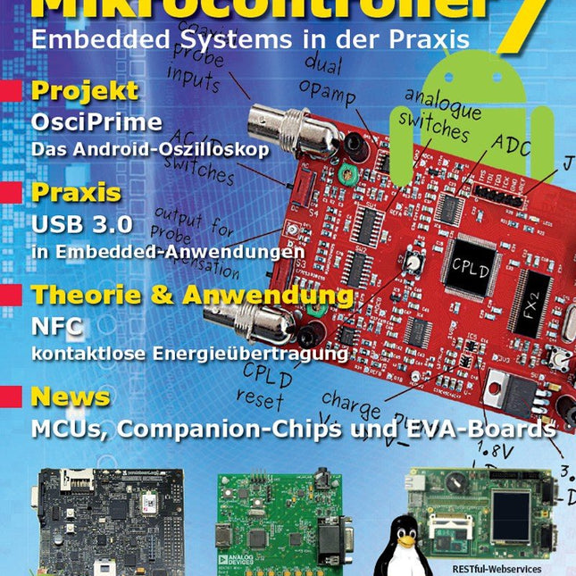
Elektor Digital Mikrocontroller 7 als PDF (DE)
Inhalt: Praxis JellyScope – Open Source Android-Oszilloskop HDMI to VGA – USB-gespeister DVI/HDMI-zu-VGA-Wandler mit Audio-Extraction WEB-ArByter – Mit dem PicosG20 Embedded-Projekte per Smartphone steuern Aufsicht – USB-2.0 und 3.0 Port-Monitor mit MSP430 Nimm Zwei – Doppel-USB-Stromversorgung Know-how Gib dem Panda Android – Linaro Android auf dem PandaBoard installieren Leinen los – Drahtlose Ladestation Qi-konform entwickeln Info Prêt-à-porter – Marktübersicht Embedded-CPU-Module Der bessere Flash-Speicher – FRAM: Funktion, Qualität und Zuverlässigkeit Transit-Chip – LPC-800: 32-Bit-ARM im 8-Bit-Gewand Don't touch – E-Feld-basierte Gestensteuerung Aktuell – MCUs, Companion-Chips, Eva-Boards und Tools Weitere Hefte aus dieser Reihe: Mikrocontroller 6 (PDF) Mikrocontroller 5 (PDF) Mikrocontroller 4 (PDF) Mikrocontroller 3 (PDF) Mikrocontroller 2 (PDF) Mikrocontroller 1 (PDF)
€ 16,90
Mitglieder: € 15,21
-

Elecrow Elecrow AI Starter Kit für Jetson Orin Nano
All-in-One-Plattform für KI-Lernen und -Entwicklung im Bereich Edge Intelligence Dieses auf dem NVIDIA Jetson Orin Nano basierende KI-Starter-Kit ist eine vielseitige Plattform für Lernen, Entwicklung und praktische Experimente im Bereich Edge AI. Das für den Einsatz mit dem NVIDIA Jetson Orin Nano konzipierte Kit kombiniert ein 11,6-Zoll-IPS-Display, eine schwenk- und neigbare 8-Megapixel-Kamera sowie ein KI-gestütztes Sprachinteraktionssystem. Es umfasst 30 Funktionsmodule und 38 sorgfältig ausgearbeitete Python-Kurse, die vom Anfänger- bis zum Fortgeschrittenenniveau reichen. Die Kursinhalte decken Python-Grundlagen, Sensortechnologie, KI-basierte Bildverarbeitung (AI Vision) und Objekterkennung ab. Dank praktischer Schritt-für-Schritt-Übungen – von der grundlegenden Programmierung bis hin zu praxisnahen Computer-Vision-Anwendungen – bietet dieses Kit eine ideale Plattform für Schüler, Maker, Entwickler und alle, die sich mit künstlicher Intelligenz und Edge Computing beschäftigen möchten. Hinweis: Der NVIDIA Jetson Orin Nano ist nicht im Lieferumfang enthalten. Features Entwickelt für den NVIDIA Jetson Orin Nano KI-Sprachinteraktionsmodul 8-MP-Kamera mit Schwenk-Neige-Steuerung Unterstützt Objekt- und Gesichtserkennung (Tracking) Kein Löten oder aufwendige Verkabelung erforderlich Integriertes 11,6-Zoll-IPS-Display 30 Funktionsmodule 38 Schritt-für-Schritt-Python-Lektionen Erweiterungsschnittstellen für I²C, UART und GPIO Tragetasche im Lieferumfang enthalten Technische Daten Hauptprozessor Jetson Orin Nano Anzahl der Sensoren 30 Design des Sensor-Boards Integriertes Sensor-Board; kein Löten oder aufwendige Verkabelung erforderlich Bildschirm 11,6-Zoll-IPS-Bildschirm Bildschirmauflösung 1366 x 768 Kamera IMX219 8 MP Erweiterungsschnittstellen 2x I²C, 1x UART, 1x IO D13, 1x IO D12 Programmierumgebung Python-basiert Anzahl der Tutorials 38 kreative Tutorials Zielgruppe Schüler, Lehrkräfte, Hardware-Enthusiasten Anwendungsszenarien Ideal zum Erlernen der KI-Programmierung und der Grundlagen des Jetson Orin Nano Abmessungen 300 x 200 x 100 mm Modulliste Modul Anzahl Temperatur- und Feuchtigkeitssensor 1 Stk. Taster 4 Stk. Ultraschall-Abstandssensor 1 Stk. Lichtsensor 1 Stk. Linear-Potentiometer 1 Stk. Summer 1 Stk. LCD 1 Stk. Infrarot-Fernbedienung 1 Stk. Relais 1 Stk. NFC 1 Stk. PIR-Bewegungssensor 1 Stk. Joystick 1 Stk. 4-stelliges Display 1 Stk. LED 1 Stk. Mikrofon 1 Stk. Lautsprecher 1 Paar Vibrationsmotor 1 Stk. Berührungssensor 1 Stk. 8x8-RGB-Matrix 1 Stk. Luftdrucksensor 1 Stk. Neigungsschalter 1 Stk. Schrittmotor 1 Stk. Beschleunigungs- und Gyroskopsensor 1 Stk. Gassensor (MQ2) 1 Stk. Hall-Sensor 1 Stk. Drehgeber (Rotary Encoder) 1 Stk. Gabellichtschranke 1 Stk. NTC 1 Stk. Servo 2 Stk. Monokulare Kamera 1 Stk. Lieferumfang 1x Elecrow AI Starter Kit für Jetson Orin Nano 1x IR-Fernbedienung 1x NFC-Karte 1x 128 GB SD-Karte 1x 40-Pin-GPIO-Kabel 2x 22-Pin-FPC-Kabel 2x 24-Pin-FPC-Kabel 1x Jetson-DP- und USB-Adapterplatine Nicht enthalten NVIDIA Jetson Orin Nano Downloads Manual Wiki OpenClaw Install and Config Guide
€ 249,00
Mitglieder: € 224,10
-

Elektor Labs Elektor Arduino Nano MCCAB Trainingsboard
Das Elektor Arduino Nano MCCAB Trainingsboard enthält alle Bauteile (inkl. Arduino Nano), die für die Übungen des "Mikrocontroller-Praxiskurs für Arduino-Einsteiger" benötigt werden wie Leuchtdioden, Schalter, Taster, akustische Signalgeber usw. Auch externe Sensoren, Motoren oder Baugruppen können mit diesem Mikrocontroller-Übungssystem abgefragt oder gesteuert werden. Technische Daten (Arduino Nano Trainingsboard MCCAB) Stromversorgung Über die USB-Verbindung des zur Erstellung der Programme sowieso angeschlossenen PCs oder ein externes Netzteil (nicht im Lieferumfang enthalten) Betriebsspannung +5 Vcc Eingangsspannung Alle Eingänge 0 V bis +5 V VX1 und VX2 +8 V bis +12 V (nur bei Verwendung eines externen Netzteils) Mikrocontrollermodul Arduino Nano Hardwareperipherie LCD 2x16 Zeichen Potenziometer P1 & P2 JP3: Auswahl der Betriebsspannung von P1 & P2 Verteiler SV4: Verteiler für die BetriebsspannungenSV5, SV6: Verteiler für die Ein-/Ausgänge des Mikrocontrollers Schalter und Taster RESET-Taster auf dem Arduino Nano-Modul6x Tastschalter K1 … K66x Schiebeschalter S1 … S6JP2: Verbindung der Schalter mit den Eingängen des Mikrocontrollers Summer Piezo-Summer Buzzer1 mit Steckbrücke auf JP6 Leuchtanzeigen LED L auf dem Arduino Nano-Modul, verbunden mit GPIO D1311x LED: Zustandsanzeige für die Ein-/AusgängeJP6: Verbindung der LEDs LD10 … LD20 mit den GPIOs D2 … D12 Serielle SchnittstellenSPI & I²C JP4: Auswahl des Signals an Pin X der SPI-Steckerleiste SV12SV9 bis SV12: SPI-Interface (3,3 V/5 V) bzw. I²C-Interface Schaltausgang für externe Geräte SV1, SV7: Schaltausgang (maximal +24 V/160 mA, extern zugeführt)SV2: 2x13 Pins zum Anschluss externer Module 3x3 LED-Matrix (9 rote LEDs) SV3: Spalten der 3x3 LED-Matrix (Ausgänge D6 … D8)JP1: Verbindung der Reihen mit den GPIOs D3 … D5 Software Library MCCABLib Steuerung der Hardware-Komponenten (Schalter, Taster, Leuchtdioden, 3x3 LED-Matrix, Summer) auf dem MCCAB Trainingsboard Betriebstemperatur bis +40 °C Abmessungen 100 x 100 x 20 mm Technische Daten (Arduino Nano) Mikrocontroller ATmega328P Architektur AVR Betriebsspannung 5 V Flashspeicher 32 KB, davon 2 KB vom Bootloader belegt SRAM 2 KB Taktfrequenz 16 MHz Analoge IN-Pins 8 EEPROM 1 KB DC-Strom pro I/O-Pin 40 mA an einem I/O-Pin, insgesamt maximal 200 mA an allen Pins gemeinsam Eingangsspannung 7-12 V Digitale I/O-Pins 22 (6 davon sind PWM-fähig) PWM-Ausgänge 6 Stromverbrauch 19 mA Abmessungen 18 x 45 mm Gewicht 7 g Lieferumfang 1x Elektor Arduino Nano Trainingsboard (MCCAB) 1x Arduino Nano
€ 69,95
Bestpreis
-
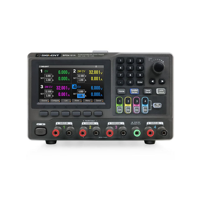
Siglent Siglent SPD4121X 4-Kanal Netzteil (285 W)
The Siglent SPD4121X is a 4-channel DC Linear Programmable Power Supply equipped with a 4.3-inch TFT-LCD display, friendly human-machine interface, and excellent performance indicators. Real-time waveform display provides engineers with an informative user interface. SPD4121X offers a total output power of 285 W with a resolution of 1 mV/1 mA. The maximum voltage and current for each channel are as follows: CH1: 15 V/1.5 A CH2: 12 V/10 A CH3: 12 V/10 A CH4: 15 V/1.5 A Features Rated output power: 285 W Rated voltage: 32 V, 12 V, 30 V Up to four high-precision power supplies with independent controllable outputs, supporting CH2 and CH3 series and parallel connections Clear graphical interface with waveform and timer display modes 5-digit voltage and current display with minimum resolution of 1 mV, 1 mA Fast output response time: <50us The high current channel support remote voltage compensation sense function. The maximum compensation voltage is 0.6 V Overvoltage protection and overcurrent protection or safe and accurate operation Equipped with a 4.3-inch TFT-LCD display (480 x 272 resolution) USB and LAN standard communication USB-GPIB module is optional Excellent channel density with up to 4 channels in a 3U half rack package Internal data storage for setups and parameters Embedded Web Server with instrument communication that doesn’t require software installation Fully SCPI programming command set support as well as a LabView driver for remote control and system automation Technische Daten SPD4323X SPD4121X SPD4306X Channel Output CH1: Voltage 0 to 6 V Current 0 to 3.2 ACH2: Voltage 0 to 32 V Current 0 to 3.2 ACH3: Voltage 0 to 32 V Current 0 to 3.2 ACH4: Voltage 0 to 6 V Current 0 to 3.2 A CH1: Voltage 0 to 15 V Current 0 to 1.5 ACH2: Voltage 0 to 12 V Current 0 to 10 ACH3: Voltage 0 to 12 V Current 0 to 10 ACH4: Voltage 0 to 15 V Current 0 to 1.5 A CH1: Voltage 0 to 15 V Current 0 to 1.5 ACH2: Voltage 0 to 30 V Current 0 to 6 ACH3: Voltage 0 to 30 V Current 0 to 6 ACH4: Voltage 0 to 15 V Current 0 to 1 A Resolution 1 mV, 1 mA 1 mV, 1 mA 1 mV, 1 mA Setting Accuracy Voltage: ±(0.03% of reading+10) mV, Current: ±(0.3% of reading+10) mA Voltage: ±(0.03% of reading+10) mV, Current: ±(0.3% of reading+10) mA Voltage: ±(0.03% of reading+10) mV, Current: ±(0.3% of reading+10) mA Readback Accuracy Voltage: ±(0.03% of reading+10) mV, Current: ±(0.3% of reading+10) mA Voltage: ±(0.03% of reading+10) mV, Current: ±(0.3% of reading+10) mA Voltage: ±(0.03% of reading+10) mV, Current: ±(0.3% of reading+10) mA Display 4.3" TFT-LCD 5-digit voltage and current display 4.3" TFT-LCD 5-digit voltage and current display 4.3" TFT-LCD 5-digit voltage and current display Output power 240 W 285 W 400 W Lieferumfang 1x Siglent SPD4121X Power Supply 1x Power cord (EU) 1x Output test cord (3 A) 1x USB cable 1x Quick start guide Downloads Datasheet Manual Quick start
€ 871,20
Bestpreis
-
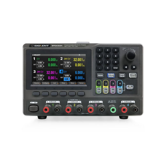
Siglent Siglent SPD4323X 4-Kanal Netzteil (240 W)
The Siglent SPD4323X is a 4-channel DC Linear Programmable Power Supply equipped with a 4.3-inch TFT-LCD display, friendly human-machine interface, and excellent performance indicators. Real-time waveform display provides engineers with an informative user interface. SPD4323X offers a total output power of 240 W with a resolution of 1 mV/1 mA. The maximum voltage and current for each channel are as follows: CH1: 6 V/3.2 A CH2: 32 V/3.2 A CH3: 32 V/3.2 A CH4: 6 V/3.2 A Features Rated output power: 240 W Rated voltage: 32 V, 12 V, 30 V Up to four high-precision power supplies with independent controllable outputs, supporting CH2 and CH3 series and parallel connections Clear graphical interface with waveform and timer display modes 5-digit voltage and current display with minimum resolution of 1 mV, 1 mA Fast output response time: <50us The high current channel support remote voltage compensation sense function. The maximum compensation voltage is 0.6 V Overvoltage protection and overcurrent protection or safe and accurate operation Equipped with a 4.3-inch TFT-LCD display (480 x 272 resolution) USB and LAN standard communication USB-GPIB module is optional Excellent channel density with up to 4 channels in a 3U half rack package Internal data storage for setups and parameters Embedded Web Server with instrument communication that doesn’t require software installation Fully SCPI programming command set support as well as a LabView driver for remote control and system automation Technische Daten SPD4323X SPD4121X SPD4306X Channel Output CH1: Voltage 0 to 6 V Current 0 to 3.2 ACH2: Voltage 0 to 32 V Current 0 to 3.2 ACH3: Voltage 0 to 32 V Current 0 to 3.2 ACH4: Voltage 0 to 6 V Current 0 to 3.2 A CH1: Voltage 0 to 15 V Current 0 to 1.5 ACH2: Voltage 0 to 12 V Current 0 to 10 ACH3: Voltage 0 to 12 V Current 0 to 10 ACH4: Voltage 0 to 15 V Current 0 to 1.5 A CH1: Voltage 0 to 15 V Current 0 to 1.5 ACH2: Voltage 0 to 30 V Current 0 to 6 ACH3: Voltage 0 to 30 V Current 0 to 6 ACH4: Voltage 0 to 15 V Current 0 to 1 A Resolution 1 mV, 1 mA 1 mV, 1 mA 1 mV, 1 mA Setting Accuracy Voltage: ±(0.03% of reading+10) mV, Current: ±(0.3% of reading+10) mA Voltage: ±(0.03% of reading+10) mV, Current: ±(0.3% of reading+10) mA Voltage: ±(0.03% of reading+10) mV, Current: ±(0.3% of reading+10) mA Readback Accuracy Voltage: ±(0.03% of reading+10) mV, Current: ±(0.3% of reading+10) mA Voltage: ±(0.03% of reading+10) mV, Current: ±(0.3% of reading+10) mA Voltage: ±(0.03% of reading+10) mV, Current: ±(0.3% of reading+10) mA Display 4.3" TFT-LCD 5-digit voltage and current display 4.3" TFT-LCD 5-digit voltage and current display 4.3" TFT-LCD 5-digit voltage and current display Output power 240 W 285 W 400 W Lieferumfang 1x Siglent SPD4323X Power Supply 1x Power cord (EU) 1x Output test cord (3 A) 1x USB cable 1x Quick start guide Downloads Datasheet Manual Quick start
€ 762,30
Bestpreis
-

Siglent Siglent SPD4306X 4-Kanal Netzteil (400 W)
The Siglent SPD4306X is a 4-channel DC Linear Programmable Power Supply equipped with a 4.3-inch TFT-LCD display, friendly human-machine interface, and excellent performance indicators. Real-time waveform display provides engineers with an informative user interface. SPD4306X offers a total output power of 400 W with a resolution of 1 mV/1 mA. The maximum voltage and current for each channel are as follows: CH1: 15 V/1.5 A CH2: 30 V/6 A CH3: 30 V/6 A CH4: 15 V/1 A Features Rated output power: 400 W Rated voltage: 32 V, 12 V, 30 V Up to four high-precision power supplies with independent controllable outputs, supporting CH2 and CH3 series and parallel connections Clear graphical interface with waveform and timer display modes 5-digit voltage and current display with minimum resolution of 1 mV, 1 mA Fast output response time: <50us The high current channel support remote voltage compensation sense function. The maximum compensation voltage is 0.6 V Overvoltage protection and overcurrent protection or safe and accurate operation Equipped with a 4.3-inch TFT-LCD display (480 x 272 resolution) USB and LAN standard communication USB-GPIB module is optional Excellent channel density with up to 4 channels in a 3U half rack package Internal data storage for setups and parameters Embedded Web Server with instrument communication that doesn’t require software installation Fully SCPI programming command set support as well as a LabView driver for remote control and system automation Technische Daten SPD4323X SPD4121X SPD4306X Channel Output CH1: Voltage 0 to 6 V Current 0 to 3.2 ACH2: Voltage 0 to 32 V Current 0 to 3.2 ACH3: Voltage 0 to 32 V Current 0 to 3.2 ACH4: Voltage 0 to 6 V Current 0 to 3.2 A CH1: Voltage 0 to 15 V Current 0 to 1.5 ACH2: Voltage 0 to 12 V Current 0 to 10 ACH3: Voltage 0 to 12 V Current 0 to 10 ACH4: Voltage 0 to 15 V Current 0 to 1.5 A CH1: Voltage 0 to 15 V Current 0 to 1.5 ACH2: Voltage 0 to 30 V Current 0 to 6 ACH3: Voltage 0 to 30 V Current 0 to 6 ACH4: Voltage 0 to 15 V Current 0 to 1 A Resolution 1 mV, 1 mA 1 mV, 1 mA 1 mV, 1 mA Setting Accuracy Voltage: ±(0.03% of reading+10) mV, Current: ±(0.3% of reading+10) mA Voltage: ±(0.03% of reading+10) mV, Current: ±(0.3% of reading+10) mA Voltage: ±(0.03% of reading+10) mV, Current: ±(0.3% of reading+10) mA Readback Accuracy Voltage: ±(0.03% of reading+10) mV, Current: ±(0.3% of reading+10) mA Voltage: ±(0.03% of reading+10) mV, Current: ±(0.3% of reading+10) mA Voltage: ±(0.03% of reading+10) mV, Current: ±(0.3% of reading+10) mA Display 4.3" TFT-LCD 5-digit voltage and current display 4.3" TFT-LCD 5-digit voltage and current display 4.3" TFT-LCD 5-digit voltage and current display Output power 240 W 285 W 400 W Lieferumfang 1x Siglent SPD4306X Power Supply 1x Power cord (EU) 1x Output test cord (3 A) 1x USB cable 1x Quick start guide Downloads Datasheet Manual Quick start
€ 1.101,10
Bestpreis
-
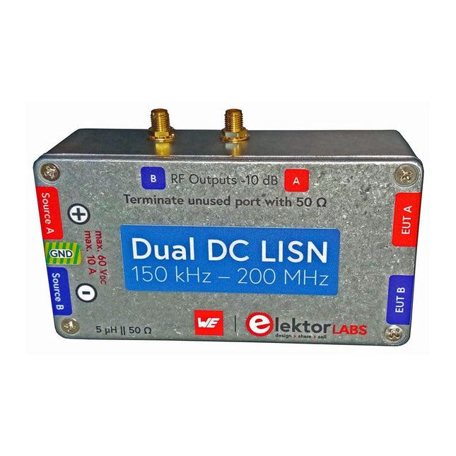
Elektor Labs Elektor Dual DC LISN (150 kHz – 200 MHz)
Die Messung der leitungsgebundenen Emission ist die einfachste und kostengünstigste Methode, um einen Hinweis darauf zu erhalten, ob ein Design die EMI/EMV-Anforderungen erfüllen kann. Ein Line Impedance Stabilization Network (LISN) ist dabei ein unverzichtbarer Bestandteil eines EMV-Prüfaufbaus (Pre-Compliance). In Zusammenarbeit mit Würth Elektronik hat Elektor einen 5 µH, 50 Ω Dual DC LISN entwickelt, der Spannungen bis zu 60 V und Ströme bis zu 10 A unterstützt. Das Gerät misst HF-Störungen auf beiden Kanälen (der Stromversorgung) mit Hilfe von 5-μH-Sperrinduktivitäten. Das interne 10-dB-Dämpfungsnetzwerk – eines in jedem Kanal – enthält einen Hochpassfilter dritter Ordnung mit einer Grenzfrequenz von 9 kHz, um den Eingang von Instrumenten wie z. B. einem Spektrumanalysator vor potenziell schädlichen Gleichspannungen oder niedrigen Frequenzen zu schützen, die vom Prüfling (EUT – Equipment Under Test) stammen. Technische Daten RF-Pfad Kanäle 2 (mit Klemmdioden) Bandbreite 150 kHz – 200 MHz Induktivität 5 μH || 50 Ω Interne Abschwächung 10 dB Steckverbinder SMA DC-Pfad Max. Strom < 10 ADC Max. Spannung < 60 VDC DC-Widerstand < 2 x 70 mΩ Platinengröße 94,2 x 57,4 mm Steckverbinder 4-mm-Bananenstecker Hammond-Gehäuse Typ 1590N Abmessungen 121 x 66 x 40 mm Lieferumfang 1x 4-lagige Platine mit allen SMD-Bauteilen bestückt 1x Vorgebohrtes Gehäuse mit vorgedrucktem Frontplattenlayout 5x Vergoldete, isolierte 4-mm-Bananenbuchsen, ausgelegt für 24 A, 1 kV 1x Hammond-Gehäuse 1590N1, Aluminium (Druckgusslegierung) Mehr Info Projekt auf Elektor Labs: Dual DC LISN for EMC pre-compliance testing Elektor 9-10/2021: EMV-Vor-Konformitätstester für Ihr Projekt mit DC-Versorgung (Teil 1) Elektor 11-12/2021: EMV-Vorkonformitätstest für Ihr DC-versorgtes Projekt (Teil 2)


