
Suchergebnisse für "assembly OR language OR essentials"
-
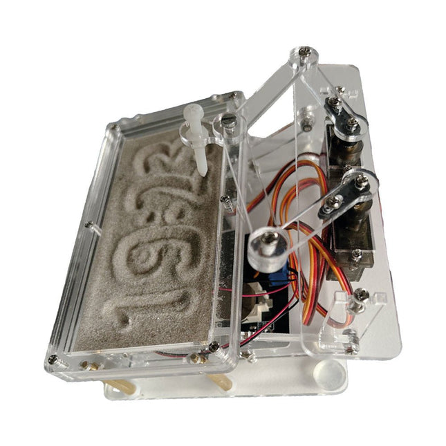
Elektor Labs Elektor Sanduhr für Raspberry Pi Pico
Raspberry Pi-basierter Eyecatcher Eine handelsübliche Sanduhr zeigt nur, wie die Zeit verrinnt. Dagegen zeigt diese Raspberry Pi Pico-gesteuerte Sanduhr die genaue Uhrzeit an, indem die vier Ziffern für Stunde und Minute in die Sandschicht „eingraviert“ werden. Nach einer einstellbaren Verzögerung wird der Sand durch zwei Vibrationsmotoren flachgedrückt und der Zyklus beginnt von vorne. Das Herzstück der Sanduhr sind zwei Servomotoren, die über einen Pantographenmechanismus einen Schreibstift antreiben. Ein dritter Servomotor hebt den Stift auf und ab. Der Sandbehälter ist mit zwei Vibrationsmotoren ausgestattet, um den Sand zu glätten. Der elektronische Teil der Sanduhr besteht aus einem Raspberry Pi Pico und einer RTC/Treiberplatine mit Echtzeituhr, plus Treiberschaltungen für die Servomotoren. Eine ausführliche Bauanleitung steht zum Download bereit. Features Abmessungen: 135 x 110 x 80 mm Bauzeit: ca. 1,5 bis 2 Stunden Lieferumfang 3x vorgeschnittene Acrylplatten mit allen mechanischen Teilen 3x Mini-Servomotoren 2x Vibrationsmotoren 1x Raspberry Pi Pico 1x RTC/Treiberplatine mit montierten Teilen Muttern, Bolzen, Abstandshalter und Drähte für die Baugruppe Feinkörniger weißer Sand
€ 49,95
Mitglieder: € 44,96
-

Elektor Digital Elektor Juli/Augustus 2020 (PDF)
ELEKTOR AIDE L'électronique dans des temps difficiles AFFICHAGE D'INFORMATION POUR LA MAISON avec Windows sur le Raspberry Pi DÉMARRER AVEC NODE-RED un outil de programmation open source basé sur des blocs visuels LA tombola d'ÉTÉ d'ELEKTOR GREATSCOTT ! CONSTRUIRE UN SYSTÈME D'ALARME LORA REVUE : ALIMENTATION DE LABORATOIRE JOY-IT RD6006 (KIT) REVUE : INTERFACEBOARD GREATFET ONE QUI N'HONNE PAS LES PETITS – XXL de la boîte à suggestions d'Elektor ANTENNE WIFI EXTERNE 2,4 GHZ POORLUIS CONTRÔLE FACILE DE LA TEMPÉRATURE MARCHE/ARRÊT AVEC CHAPEAU RASPBERRY PI COMMENT PRENDRE DE (BONNES) PHOTOS DÈS L'IMPRESSION... ...et les composants électroniques ? REVUE : NOYAU I2CDRIVER ÉCRAN TACTILE JOY-VIEW 13 DE JOY-IT BOOSTER LED POUR MICROCONTRÔLEURS avec un seul composant ! MACHINE À LAVER À ULTRASONS EXPÉRIMENTALE REVUE : GÉNÉRATEUR DE SIGNAUX JOY-IT JDS2915 générateur de signaux doubles avec compteur de fréquence dans un boîtier métallique PROGRAMMATION DES FEUX DE SIGNALISATION EN LANGAGE PIC ASSEMBLY LED CLIGNOTANT PERMANENT CAPTEUR DE HALL EXPÉRIMENTAL DÉTECTER LES COURT-CIRCUITS AVEC UN MILLIOHM OU ESR MÈTRE KIT PRATIQUE ÉLECTRIQUE SDR PIPELINE DE LABORATOIRES ÉLECTRIQUES KICK-STARTER ÉLECTRIQUE ....eh bien, vous voyez ce que nous voulons dire. AVEZ-VOUS VRAIMENT BESOIN DE TOUT ÇA ??? ici, je passe de nombreuses heures sur des projets électroniques... LABORATOIRE EST OUEST MEILLEUR un aperçu du plus saint des saints, où naissent des projets intéressants BONJOUR LE MONDE! NOUS SOMMES ELEKTOR ET NOUS SOMMES SOCIAUX M4 + A7 + GPU : UNE ÉQUIPE DE RÊVE INÉGALE le nouveau SoC STM32MP1 pour les travaux plus lourds CONFIGURATION DE TEST POUR LE 16F18877 ET AUTRES GRANDES PHOTOS COMMUNICATION INTER-ΜC AVEC LE BUS SPI ET ATMEGA328P SIX VARIANTES DE L'OSCILLATEUR LF/AF (et la capacité de M. Miller) BBC MICRO:BIT oscilloscope absolument minimaliste avec affichage LED FEU DE RUNNING À LED 'KNIGHT RIDER' AVEC ESP32 GÉNÉRATEUR DE SIGNAUX AM LW/MW AVEC ATTINY13 DIPMÈTRE ABSOLUMENT MINIMALISTE SCOOTERS ÉLECTRIQUES BON MARCHÉ quelle est la qualité d'un scooter électrique « homologué » à 300 euros de Lidl ? AIDE AU STATIONNEMENT À ULTRASONS AVEC ARDUINO UNO PÉDALE DE DISTORSION AVEC AMPLI OP ET TUBES DE CHARGE SPATIALE INDISPENSABLE POUR CHAQUE LABORATOIRE D'ÉLECTRONIQUE HEXADOKU IA POUR DÉBUTANTS (2) réseaux de neurones avec Linux et Python
€ 9,95
-

Elektor Digital Elektor January/February 2026 (PDF) EN
Elektor GREEN and GOLD members can download their digital edition here. Not a member yet? Click here. Low-Noise Lab Power Supply (1)A Quiet Source for Sensitive Circuits STM32 Edge AI Contest 2025: The Winners Batteries TodayTechnology and Differences in Lithium Batteries Adjustable Electronic LoadStatic + Dynamic DC Load Step-Down Converter from 48 V to 5 VThe Story of Circuit Development Autonomous Sensor Node v2.0Part 2: Hardware Validation and Power Optimizations VaristorsPeculiar Parts, the Series Graphical Grid Frequency MeterMonitor Grid Quality Starting Out in Electronics……Brings Its Own End Peak Current Load SMD FerritesMore Resilient Against Current Peaks Elektor Live! Expert Day 2025 Energy Harvesting Set to Accelerate IoT and IIoT Use CasesHow Energy Harvesting Frees IoT from the Grid Fnirsi DPS-150Compact and Portable Power Supply and Converter Adjustable USB-C Power SourceTurn Your USB-C Charger Into an Adjustable Power Supply Simple Charger and Capacity TesterWith Two Cheap “Off-the-Shelf” Modules Smart Color Detector with AI Voice and Playback PbMonitor v2.0Introduction to the Updated Battery Monitoring System A Fan for the Mini Reflow PlateSmart Modifications That Improve Results From Life’s ExperienceThe Tsunami of Indulgence Err-lectronicsCorrections, Updates, and Readers’ Letters 2026: An AI OdysseyWhen Models Start Dictating the Hardware Precision Picoammeter (2)Assembling, Calibration, and Test Wireless Device Poweringwith Inductive Technology AI-Based Autonomous DrivingThe RDW’s Self Driving Challenge 2024 Sound Card as Signal GeneratorPC as DCF77 Test Transmitter
€ 9,50
-

Elektor Digital Elektor September/October 2020 (PDF) EN
Elektor Magazine DE September/Oktober 2020 (PDF)
€ 7,50
-

Great Scott Gadgets Acrylgehäuse für HackRF SDR
Dieses durchsichtige Acrylgehäuse ist das offizielle Gehäuse für das HackRF One/Pro Board. Es kann das schwarze Standard-Kunststoffgehäuse des HackRF One/Pro ersetzen. Montageanleitung Verwenden Sie einen Gitarrenpick oder einen Spudger, um die HackRF One/Pro Platine aus dem schwarzen Kunststoffgehäuse zu ziehen. Setzen Sie eine lange Schraube in jede Ecke der unteren Acrylplatte ein. Sichern Sie jede lange Schraube mit einem kurzen (5 mm) Abstandshalter auf der gegenüberliegenden Seite der Platte. Legen Sie die HackRF One/Pro Platine (mit der Oberseite nach oben) auf die untere Platte und führen Sie die Enden der langen Schrauben durch die Befestigungslöcher in den Ecken der Leiterplatte. Sichern Sie die Platine mit einem langen (6 mm) Abstandshalter in jeder Ecke. Legen Sie die obere Acrylplatte auf die Leiterplatte und richten Sie die Ausschnitte mit den Erweiterungsleisten der Leiterplatte aus. Sichern Sie jede Ecke mit einer kurzen Schraube. Wichtig: Bei jedem Schritt nur handfest (nicht zu fest) anziehen.
€ 19,95
Mitglieder: € 17,96
-

Elektor Digital Elektor May/June 2023 (PDF)
Elektor GREEN and GOLD members can download their digital edition here. Not a member yet? Click here. Knowledge for All! Super Servo TesterTest Up to Four Servos Stand-Alone or In-System Analog Signals and MicrocontrollersADCs, DACs, Current Measurement, and More embedded world 2023 Sub-Nyquist Sampling in PracticeReliably Capturing Higher Frequencies Using Subsampling Android Smartphone Here, ESP32 There?Practical Pproject Using the Android Wi-Fi API Active 1-kHz Filter for Distortion MeasurementBetter Measurements Through Optimization of the Measurement Signal Starting Out in Electronics......Multivibrating Cheerfully Further! Err-lectronicsCorrections, Updates and Readers’ Letters The New I3C ProtocolA Worthy Successor to I²C, or Just More Hot Air? BlueRC: IR Remote Control with Smartphone and ESP32Adaptive and Universal Microcontroller Documentation Explained (Part 2)Registers and Block Diagrams Automating Test and MeasurementProgramming Test Equipment to Do What You Want Infographics: Test and Measurement Overvoltage Protection for Safe OperationTransient Protection for Non-Isolated DC/DC Power Modules Wiha Measuring EquipmentReliable Electrical Testers and Meters Automating Testing and Collaborating on Test Results From Life’s ExperienceHigh-Level Electronics Energy LoggerMeasuring and Recording Power Consumption Assembling the 4tronix M.A.R.S. Rover Kit Parking Disk with E-Paper DisplayAn Innovative Digital Replacement eCO₂ Telegram botAir-Quality Measurement with Telegram Notification Behind the Scenes of DIY High-End AudioElektor’s Ton Giesberts Interviewed on the Fine Art of Analog Design HomeLab ToursWork in Progress... RFID Tag Reading and RFID Door LockSample Projects from the Elektor Arduino Experimenting Bundle Oscilloscope Current Probe for RFRF Current Measurements Made Easy Not for the Faint-Hearted: Robot Arm KitWith Raspberry Pi Pico and MicroPython Generative AIWho Made This Anyway? Hexadoku
€ 7,50
-

Elektor Digital Elektor July/August 2023 (PDF)
Elektor GREEN and GOLD members can download their digital edition here. Not a member yet? Click here. Rotary Dial Phone as Remote ControlTo Switch On the Lights, Dial 1; For the Coffee Maker, Dial 2 GPS-Based Speed MonitorNo More Speeding Tickets RGB Stroboscope with ArduinoA Colorful Adaptation of a Useful Instrument Wireless Emergency Push ButtonEnhanced Safety with LoRa Starting Out in ElectronicsFollow the Emitter Arbitrary, Independent Hysteresis Levels for Comparatorswith Simulations, Spreadsheets and Algebra ESP32-Based Impedance AnalyzerSimple, Low-Part-Count, and Inexpensive! HomeLab ToursEncouraging DIY The MCCAB Arduino Nano Training BoardAll-in-One Hardware for the “Microcontrollers Hands-On Course” From Life’s ExperienceModern Luddism Sensor 101: The DS18B20 Temperature SensorConnection to the 1-Wire Bus Is Matter the Thread to Save the Smart Home?New Standards to Simplify the Smart Home A Matter of CollaborationDeveloping with the Thing Plus Matter Board and Simplicity Studio Infographics: IoT and Sensors Matter, ExpressLink, Rainmaker — What Is This All About?Q&A with Amey Inamdar, Technical Marketing Director at Espressif Selecting Microcontroller Dev Kits for IoT and IIoT ApplicationsAn Introductory Guide Capacitors Do Not Always Behave Capacitively! An NTP Clock with CircuitPythonWhy Should You Use This Programming Language? Build a Cool IoT DisplayWith the Phambili Newt The HB100 Doppler Motion SensorTheory and Practice A Bare-Metal Programming Guide (Part 1)For STM32 and Other Controllers Siglent SDM3045X Multimeter Microprocessors for Embedded SystemsPeculiar Parts, the Series Microcontroller Documentation Explained (Part 3)Block Diagrams and More Low-Power LoRa Weather StationBuild a long-range weather station by yourself Transverter for the 70 cm Band Climate Calling EngineersMove Fast and Fix Things Hexadoku
€ 7,50
-

Seeed Studio Seeed Studio RF Explorer 3G Combo Spektrum-Analyzer
The Seeed Studio RF Explorer 3G Combo is a handheld digital spectrum analyzer and an affordable tool for working across a wide range of popular frequency bands. It is based on a highly integrated frequency synthesizer and a double-balanced mixer, providing high performance, compact dimensions, low power consumption, and excellent value. Designed for both indoor and outdoor use, the RF Explorer 3G Combo can also be connected to a PC via a standard Mini-USB 2.0 connector for additional functionality. This model combines a WSUB1G base unit with an RFEMWSUB3G expansion module, supplied fully assembled and tested. It features two SMA connectors and includes two antennas: a dual-band 144/430 MHz telescopic antenna for sub-GHz frequencies and a helical whip antenna for the 2.4 GHz band. Additional frequency-specific antennas may be required for optimal performance in certain supported frequency ranges. This combination provides the wide frequency coverage of the WSUB3G module together with the high sensitivity and fast response of the WSUB1G unit in the commonly used sub-1 GHz frequency range. Features Pocket size and light weight Solid aluminum metal case Includes a transport EVA carry case for RF Explorer Spectrum Analyzer mode with Peak Max and Hold, Normal, Overwrite and Averaging modes Lifetime free firmware upgrades available, open to community requested features High capacity Lipo for 16+ hours of continuous run, rechargeable by USB Windows PC client Open Source Can be extended with internal Expansion Modules for additional band and functionality Wide band coverage to all popular RF frequencies, starting at 15 MHz and going up to 2.7 GHz. This includes very interesting frequency areas such as 2 m HAM radio, all VHF and UHF, FM radio, GPS, WiFi and WiMax, Bluetooth, etc. Firmware: RF Explorer 3G Combo is delivered with upgraded firmware v1.09. Note some of the features and operation accuracy will be improved in upcoming free firmware revisions. Technische Daten Battery Lithium Cells / Batteries contained in equipment UN3481 - PI967 Frequency band 15-2700 MHz Frequency span 112 KHz - 600 MHz Graphics LCD 128 x 64 pixels, great visibility outdoors PC Windows client Supports Windows (32 and 64 bits) Backlight For great indoor visibility 2 standard SMA 50 ohms connector, One for Sub-GHz wideband Nagoya NA-773 telescopic antenna included and another 2.4 GHz one for 15-2700 MHz band with helical antenna included. Amplitude resolution 0.5 dBm Dynamic range Left SMA port (WSUB1G) -115 dBm to 0 dBm Right SMA port (WSUB3G) -110 dBm to -10 dBm Absolute Max input power Left SMA port (WSUB1G) +5 dBm Right SMA port (WSUB3G) +30 dBm Average noise level (typical) -110 dBm Frequency stability and accuracy (typical) ±10 ppm Amplitude stability and accuracy (typical) ±6 dBm Frequency resolution 1 KHz Resolution bandwidth (RBW) Automatic 3 KHz to 600 KHz Weight 185 g Dimensions 113 x 70 x 25 mm Lieferumfang Seeed Studio RF Explorer 3G Combo Spectrum Analyzer Nagoya NA-773 wideband telescopic antenna 2.4 GHz band antenna EVA Case Dokumentation For more info and to get started with your RF Explorer, visit the start page. For questions and support, please visit https://support.rf-explorer.com
€ 275,32
-

Elektor January/February 2026 (EN)
Elektor GREEN and GOLD members can download their digital edition here. Not a member yet? Click here. Low-Noise Lab Power Supply (1)A Quiet Source for Sensitive Circuits STM32 Edge AI Contest 2025: The Winners Batteries TodayTechnology and Differences in Lithium Batteries Adjustable Electronic LoadStatic + Dynamic DC Load Step-Down Converter from 48 V to 5 VThe Story of Circuit Development Autonomous Sensor Node v2.0Part 2: Hardware Validation and Power Optimizations VaristorsPeculiar Parts, the Series Graphical Grid Frequency MeterMonitor Grid Quality Starting Out in Electronics……Brings Its Own End Peak Current Load SMD FerritesMore Resilient Against Current Peaks Elektor Live! Expert Day 2025 Energy Harvesting Set to Accelerate IoT and IIoT Use CasesHow Energy Harvesting Frees IoT from the Grid Fnirsi DPS-150Compact and Portable Power Supply and Converter Adjustable USB-C Power SourceTurn Your USB-C Charger Into an Adjustable Power Supply Simple Charger and Capacity TesterWith Two Cheap “Off-the-Shelf” Modules Smart Color Detector with AI Voice and Playback PbMonitor v2.0Introduction to the Updated Battery Monitoring System A Fan for the Mini Reflow PlateSmart Modifications That Improve Results From Life’s ExperienceThe Tsunami of Indulgence Err-lectronicsCorrections, Updates, and Readers’ Letters 2026: An AI OdysseyWhen Models Start Dictating the Hardware Precision Picoammeter (2)Assembling, Calibration, and Test Wireless Device Poweringwith Inductive Technology AI-Based Autonomous DrivingThe RDW’s Self Driving Challenge 2024 Sound Card as Signal GeneratorPC as DCF77 Test Transmitter
€ 14,90
-

Elektor Digital Elektor September/October 2021 (PDF)
UNDERSTANDING THE NEURONS IN NEURAL NETWORKS (PART 1)Artificial Neurons EMC PRE-COMPLIANCE TEST FOR YOUR DC-POWERED PROJECT (PART 1)Dual DC LISN ELECTRONIC LOAD FOR DC AND ACUp to 400 V and 10 A (Peak) STARTING OUT IN ELECTRONICSEasier Than Imagined! ...Taking on the Choke! IMAGE PROCESSING WITH THE NVIDIA JETSON NANO (PART 1)The Hardware and Software AN IN-DEPTH LOOK AT MAINS TRANSFORMERSHow Do They Behave When They Are Switched On and Off? YES WE CAN WITH PICAN 3A CAN Bus HAT for the Raspberry Pi 4 BALCONY POWER PLANTDIY Solar Balcony = Speedy Payback! IMAGING AND VIDEO-STREAMING WITH A RASPBERRY PI 4The Raspberry Pi High-Quality Camera in Practice USING DISPLAYS IN RASPBERRY PI PROJECTSSample Chapter: Organic Light Emitting Diode Displays (OLED) HANDS ON THE PARALLAX PROPELLER 2 (PART 4)Sending Strings ELEKTOR @ 60A Look Back at Previous Septembers HOMELAB TOURSIn the Friesian Countryside, Where the Tubes Bloom ... HYBRIDSPeculiar Parts, the series A COMPASS ROSE USING THE GY-271Or Why We Move in Figures of Eight to Calibrate a Sensor FINDING YOUR FOOTPRINTCalculate the Carbon Footprint of Your Electronics ESP32-CONNECTED THERMOSTATKeep Your Wine at the Right Temperature! MAGNETIC LEVITATION THE DIGITAL WAYESP32 Pico Replaces the Analog Comparator ULTIMATE ARDUINO UNO HARDWARE MANUALSample Chapter: Main Microcontroller Bootloader MICROPYTHON FOR THE ESP32 AND FRIENDS (PART 2)Control Matrix Displays Easily MADMACHINE SWIFTIO BOARDModern Language Meets Modern Hardware FROM LIFE’S EXPERIENCEOn-Again, Off-Again Relationship HEXADOKUThe Original Elektorized Sudoku
€ 7,50
-
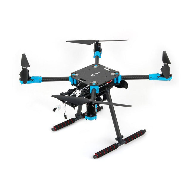
Holybro Holybro X500 V2 ARF Drohnen-Kit
Das X500 V2 ARF-Kit ist ein erschwingliches, leichtes und robustes professionelles Drohnen-Kit aus Kohlefaser, das einfach zusammenzubauen ist (weniger als 15 Minuten). Es wird mit dem X500 V2-Rahmenkit und vorinstallierten Motoren, Reglern, Stromverteilerplatinen und Propellern geliefert. Es ist perfekt kompatibel mit verschiedenen Flugsteuerungen wie der Holybro Pixhawk-Serie, Durandal, Pix32 V5 usw. Im Vergleich zum Vorgängermodell gibt es zahlreiche Verbesserungen. Technische Daten Radstand: 500 mm Motormontagemuster: 16x16 mm Rahmenkörper: 144x144 mm, 2 mm dick Fahrwerkshöhe: 215 mm Abstand zwischen Ober- und Unterplatte: 28 mm Gewicht: 610 g Flugzeit: ca. 18 Minuten im Schwebeflug ohne zusätzliche Nutzlast. Getestet mit 5000 mAh-Akku. Nutzlast: 1500 g (ohne Akku) Batterieempfehlung: 4S 3000-5000 mAh 20C+ mit XT60 Lipo-Batterie (nicht im Lieferumfang enthalten) Lieferumfang X500 V2 Rahmenkit Mit vorinstallierten Elementen: 4x Motoren: Holybro 2216 KV920 Motor (4 Stück) mit XT30-Stecker 4x Regler (BLHeli S ESC 20A) 6x 1045 Propeller Stromverteilungsplatine – XT60-Stecker für Batterie & XT30-Stecker für ESCs & Peripheriegeräte Hinweis: Die Tiefenkamerahalterung ist separat erhältlich.
€ 379,95
Bestpreis
-

Siglent Siglent SDS1104X-E 4-Kanal Oszilloskop (100 MHz)
Das Siglent SDS1104X-E verwendet eine neue Generation der SPO (Super Phosphor Oscilloscope) Technologie, die eine exzellente Signalgenauigkeit und -leistung bietet. Das Systemrauschen ist auch niedriger als bei ähnlichen Produkten in der Branche. Es kommt mit einem minimalen vertikalen Eingangsbereich von 500 uV/div, einem innovativen digitalen Trigger-System mit hoher Empfindlichkeit und geringem Jitter sowie einer Wellenform-Aufnahme-Rate von 400.000 Bildern/sek (Sequenzmodus). Das SDS1104X-E verfügt auch über eine 256-Stufen-Intensitätsgradierungsfunktion und einen Farbtemperatur-Anzeigemodus, die in anderen Modellen dieser Klasse nicht zu finden sind. Die neuesten Oszilloskope von SIGLENT unterstützen mehrere leistungsstarke Trigger-Modi, einschließlich Serial Bus Triggering. Die serielle Dekodierung ist kostenlos und umfasst IIC, SPI, UART, CAN und LIN. Die Aufzeichnung von Verlaufs-Wellenformen und sequentielles Triggern ermöglichen eine erweiterte Wellenform-Aufzeichnung und -Analyse. Eine weitere leistungsstarke Ergänzung ist die neue 1-Mpt-FFT-Mathematikfunktion, die dem SDS1104X-E eine sehr hohe Frequenzauflösung beim Beobachten von Signal-Spektren gibt. Features Intelligenter Trigger: Edge, Slope, Pulse Width, Window, Runt, Interval, Timeout (Dropout) und Pattern Kostenloses Serial Bus Triggering und Dekodierung: IIC, SPI, UART, RS232, CAN und LIN Video-Trigger und Unterstützung für HDTV Niedriges Hintergrundrauschen und Spannungsbereiche von 500 μV/div bis 10 V/div 10 Arten von Ein-Knopf-Verknüpfungen, unterstützt Auto Setup, Default, Cursors, Measure, Roll, History, Display/Persist, Clear Sweep, Zoom und Print Segmentierte Erfassung (Sequenz) Modus, der die maximale Aufzeichnungslänge in mehrere Segmente (bis zu 80.000) unterteilt, je nach vom Benutzer festgelegten Triggerbedingungen, mit einem sehr kleinen Segment mit geringer Verzögerungszeit, um das qualifizierende Ereignis zu erfassen. Verlaufs-Wellenaufzeichnung (History) Funktion, die maximale aufgezeichnete Wellenformlänge beträgt 80.000 Bilder Automatische Messfunktion für 38 Parameter, unterstützt Statistik-, Gate-Messung, Math-Messung, History-Messung und Ref-Messung 1 Mpt FFT Echte Messung und Mathematik können alle 14 Mpts des Speichers nutzen Voreinstellungstasten können für Benutzereinstellungen oder werkseitige 'Standardeinstellungen' angepasst werden Sicherheits-Löschmodus Highspeed-Hardware-basierte Pass/Fail-Funktion Großer 7-Zoll-TFT-LCD-Bildschirm mit 800 * 480 Auflösung Mehrere Schnittstellentypen: USB-Host, USB-Gerät (USB-TMC), LAN (VXI-11), Pass/Fail, Trigger Out Unterstützt SCPI-Fernsteuerbefehle Mehrsprachige Anzeige und eingebettete Hilfe Browser-Steuerung/Onboard-Webseite zur softwarefreien Überwachung (nur 4-Kanal-Modelle) Lieferumfang 1x Siglent SDS1104X-E Oszilloskop 4x 100 MHz Sonden 1x Garantiekarte 1x Netzkabel 1x USB-Kabel 1x Schnellstartanleitung Downloads Datasheet Manual Programming Guide
€ 508,71
Bestpreis


