Quite unintentionally a one-page story on an old Heathkit tube tester in the December 2004 edition of Elektor magazine spawned dozens of ‘Retronics’ tales appearing with a monthly cadence, and attracting a steady flow of reader feedback and contributions to the series. Since launching his Retronics columns, Elektor Editor Jan Buiting has never been short of copy to print, or vintage equipment to marvel at.
This book is a compilation of about 80 Retronics installments published between 2004 and 2012. The stories cover vintage test equipment, prehistoric computers, long forgotten components, and Elektor blockbuster projects, all aiming to make engineers smile, sit up, object, drool, or experience a whiff of nostalgia.
To reflect that our memories are constantly playing tricks on us, and honoring that “one man’s rubbish is another man’s gem”, the tales in the book purposely have no chronological order, and no bias in favor of transistor or tube, microprocessor or discrete part, audio or RF, DIY or professional, dry or narrative style.
Although vastly diff erent in subject matter, all tales in the book are told with personal gusto because Retronics is about sentiment in electronics engineering, construction and repair, be it to reminisce about a 1960s Tektronix scope with a cleaning lady as a feature, or a 1928 PanSanitor box for dubious medical use.
Owners of this book are advised to not exceed one Retronics tale per working day, preferably consumed in the evening hours under lamp light, in a comfortable chair, with a piece of vintage electronic equipment close and powered up.
Elektor GREEN en GOLD leden kunnen deze uitgave hier downloaden.
Nog geen lid? Klik hier om een lidmaatschap af te sluiten.
DHZ-accusysteem voor zonne-energiebouw uw eigen energieopslag voor zonnepanelen
Simulator voor zonnepanelentest en optimaliseer MPP-trackers en omvormers
De STM32 Edge-AI-ContestOntdek de nieuwe STM32N6 en ding mee naar € 5000!
Vergroten van de bandgapdaarom is er zoveel interesse in SiC en GaN
Powerbank voor noteboekgeef uw oude laptop een tweede leven
Medische robotshet overwinnen van technische en regelgevende barrières
Vorstbescherming voor fruitbomenmet temperatuurlogger
Het analoge dingde Arduino onder de analoge computers?
Zuinige relaisdriverspaart 90% spoelstroom
Verbetering van de ET5410A+ DC-belastingblijf koel en stil
electronica 2024een terugblik
Elektromagnetische compatibiliteitEMC in een notendop!
Alle begin......filtert actief
Reduceer vermogensverlies met seriecondensatorenslim gebruik van capacitieve reactantie
De betaalbare MCP4725 12-bit digitaal/analoog-omzetterEEPROM-functie zorgt voor veilig inschakelgedrag
FNIRSI LCR-ST1 smart LCR-meetpincet
Raspberry Pi-gebaseerd test- en meetlabals eerste: de ADC
Elektronische belastingweerstandmet onderdelen die u waarschijnlijk hebt liggen
2025: een AI-odysseeenkele projecten voor het nieuwe jaar
Project-update: AmpVolt v2.0100 ampère en meer!
Project 2.0correcties, updates en brieven van lezers
Ethische transparantie ontsluierdinzichten uit het Ethics in Electronics 2024 onderzoek
Audio DSP FX Processor Boarddeel 2: toepassingen maken
If you have the right tools, designing a microprocessor shouldn’t be complicated. The Verilog hardware description language (HDL) is one such tool. It can enable you to depict, simulate, and synthesize an electronic design, and thus increase your productivity by reducing the overall workload associated with a given project.Monte Dalrymple’s Microprocessor Design Using Verilog HDL is a practical guide to processor design in the real world. It presents the Verilog HDL in a straightforward fashion and serves as a detailed introduction to reducing the computer architecture and as an instruction set to practice. You’re led through the microprocessor design process from start to finish, and essential topics ranging from writing in Verilog to debugging and testing are laid bare.The book details the following, and more:
Verilog HDL Review: data types, bit widths/labeling, operations, statements, and design hierarchy
Verilog Coding Style: files vs. modules, indentation, and design organization
Design Work: instruction set architecture, external bus interface, and machine cycle
Microarchitecture: design spreadsheet and essential worksheets (e.g., Operation, Instruction Code, and Next State)
Writing in Verilog: choosing encoding, assigning states in a state machine, and files (e.g., defines.v, hierarchy.v, machine.v)
Debugging, Verification, and Testing: debugging requirements, verification requirements, testing requirements, and the test bench
Post Simulation: enhancements and reduction to practice
Monte Dalrymple received a BSEE (with highest honors) and an MSEE from the University of California at Berkeley, where he was elected to Phi Beta Kappa. Monte started his career at Zilog, where he designed a number of successful products, including the Serial Communication Controller (SCC) family and the Universal Serial Controller (USC) family. He was also the architect and lead designer of the Z380 microprocessor. Monte started his own company, Systemyde International Corp., in 1995, and has been doing contract design work ever since. He designed all five generations of Rabbit microprocessors, a Z180 clone that is flying on the Juno mission to Jupiter, and a Z8000 clone that flies in a commercial avionics air data computer. Monte holds 16 patents as well as both amateur and commercial radio licenses. Monte wrote 10 articles for Circuit Cellar magazine between 1996 and 2010. He recently completed a side project to replace the CPU in an HP-41C calculator with a modern FPGA-based version.
Das Siglent SDS1104X-E verwendet eine neue Generation der SPO (Super Phosphor Oscilloscope) Technologie, die eine exzellente Signalgenauigkeit und -leistung bietet. Das Systemrauschen ist auch niedriger als bei ähnlichen Produkten in der Branche. Es kommt mit einem minimalen vertikalen Eingangsbereich von 500 uV/div, einem innovativen digitalen Trigger-System mit hoher Empfindlichkeit und geringem Jitter sowie einer Wellenform-Aufnahme-Rate von 400.000 Bildern/sek (Sequenzmodus).
Das SDS1104X-E verfügt auch über eine 256-Stufen-Intensitätsgradierungsfunktion und einen Farbtemperatur-Anzeigemodus, die in anderen Modellen dieser Klasse nicht zu finden sind. Die neuesten Oszilloskope von SIGLENT unterstützen mehrere leistungsstarke Trigger-Modi, einschließlich Serial Bus Triggering. Die serielle Dekodierung ist kostenlos und umfasst IIC, SPI, UART, CAN und LIN. Die Aufzeichnung von Verlaufs-Wellenformen und sequentielles Triggern ermöglichen eine erweiterte Wellenform-Aufzeichnung und -Analyse. Eine weitere leistungsstarke Ergänzung ist die neue 1-Mpt-FFT-Mathematikfunktion, die dem SDS1104X-E eine sehr hohe Frequenzauflösung beim Beobachten von Signal-Spektren gibt.
Features
Intelligenter Trigger: Edge, Slope, Pulse Width, Window, Runt, Interval, Timeout (Dropout) und Pattern
Kostenloses Serial Bus Triggering und Dekodierung: IIC, SPI, UART, RS232, CAN und LIN
Video-Trigger und Unterstützung für HDTV
Niedriges Hintergrundrauschen und Spannungsbereiche von 500 μV/div bis 10 V/div
10 Arten von Ein-Knopf-Verknüpfungen, unterstützt Auto Setup, Default, Cursors, Measure, Roll, History, Display/Persist, Clear Sweep, Zoom und Print
Segmentierte Erfassung (Sequenz) Modus, der die maximale Aufzeichnungslänge in mehrere Segmente (bis zu 80.000) unterteilt, je nach vom Benutzer festgelegten Triggerbedingungen, mit einem sehr kleinen Segment mit geringer Verzögerungszeit, um das qualifizierende Ereignis zu erfassen.
Verlaufs-Wellenaufzeichnung (History) Funktion, die maximale aufgezeichnete Wellenformlänge beträgt 80.000 Bilder
Automatische Messfunktion für 38 Parameter, unterstützt Statistik-, Gate-Messung, Math-Messung, History-Messung und Ref-Messung
1 Mpt FFT
Echte Messung und Mathematik können alle 14 Mpts des Speichers nutzen
Voreinstellungstasten können für Benutzereinstellungen oder werkseitige 'Standardeinstellungen' angepasst werden
Sicherheits-Löschmodus
Highspeed-Hardware-basierte Pass/Fail-Funktion
Großer 7-Zoll-TFT-LCD-Bildschirm mit 800 * 480 Auflösung
Mehrere Schnittstellentypen: USB-Host, USB-Gerät (USB-TMC), LAN (VXI-11), Pass/Fail, Trigger Out
Unterstützt SCPI-Fernsteuerbefehle
Mehrsprachige Anzeige und eingebettete Hilfe
Browser-Steuerung/Onboard-Webseite zur softwarefreien Überwachung (nur 4-Kanal-Modelle)
Lieferumfang
1x Siglent SDS1104X-E Oszilloskop
4x 100 MHz Sonden
1x Garantiekarte
1x Netzkabel
1x USB-Kabel
1x Schnellstartanleitung
Downloads
Datasheet
Manual
Programming Guide
Elektor GREEN en GOLD leden kunnen deze uitgave hier downloaden.
Nog geen lid? Klik hier om een lidmaatschap af te sluiten.
OBD2-sensordashboardOude meters vormden het startpunt van een zoektocht naar echte gegevens
OBD2: voeg een toerenteller en schakelindicator toe aan je autoRetro, maar uiterst nuttig
LiDAR- en Visiesensoren voor Robotica
Sensor+Test 2025 en PCIM 2025
Contactloze E-Veldmetingen (1)Een Trillende Membraan voor het Detecteren van Gelijkspanningen of Statische Elektrische Velden
Draadloze brievenbusmeldervan optische sensoren tot radar: enkele mogelijkheden
Elektor Mini-Wheelieeen zelfbalancerende robot
ZonnecellenVreemde onderdelen, de serie
Aan de slag met een moderne radarsensorStaat een nauwkeurige meting op uw radar?
Uit het leven gegrepenpapierfabriek
CybersecurityZware tijden voor hackers
Infographics: IoT en sensoren 2025
Bluetooth 6.0 brengt verbeterde toepassingen voor afstandsbepalingNieuwe versie biedt betere apparaatpositionerings- en -locatieservices
Draadloze communicatie verkennen met BeagleY-AI
Err-lectronicsCorrecties, updates en lezerspost
Alle begin......sluit het thema opamps af
Een krachtige AI-codeerassistentsneller ontwikkelen met Continue en Visual Studio Code
Zonne-laadregelaar met MPPT (2)Het schema
Ultrasone obstakeldetectoreen eenvoudig project om slechtzienden te helpen
2025: Een AI-odysseeHalfjaaroverzicht
Raspberry Pi Standalone MIDI-synthesizer (3)Het slimmer maken en een gebruikersinterface toevoegen
Meshtastic: een demonstratieprojectEen slim netwerk van LoRa-radio's
Analoge audio-frequentiegeneratorHoogwaardige sinusgenerator met instelbare frequentie
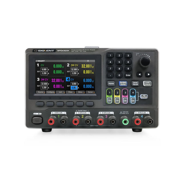
The Siglent SPD4323X is a 4-channel DC Linear Programmable Power Supply equipped with a 4.3-inch TFT-LCD display, friendly human-machine interface, and excellent performance indicators. Real-time waveform display provides engineers with an informative user interface.
SPD4323X offers a total output power of 240 W with a resolution of 1 mV/1 mA. The maximum voltage and current for each channel are as follows:
CH1: 6 V/3.2 A
CH2: 32 V/3.2 A
CH3: 32 V/3.2 A
CH4: 6 V/3.2 A
Features
Rated output power: 240 W
Rated voltage: 32 V, 12 V, 30 V
Up to four high-precision power supplies with independent controllable outputs, supporting CH2 and CH3 series and parallel connections
Clear graphical interface with waveform and timer display modes
5-digit voltage and current display with minimum resolution of 1 mV, 1 mA
Fast output response time: <50us
The high current channel support remote voltage compensation sense function. The maximum compensation voltage is 0.6 V
Overvoltage protection and overcurrent protection or safe and accurate operation
Equipped with a 4.3-inch TFT-LCD display (480 x 272 resolution)
USB and LAN standard communication
USB-GPIB module is optional
Excellent channel density with up to 4 channels in a 3U half rack package
Internal data storage for setups and parameters
Embedded Web Server with instrument communication that doesn’t require software installation
Fully SCPI programming command set support as well as a LabView driver for remote control and system automation
Technische Daten
SPD4323X
SPD4121X
SPD4306X
Channel Output
CH1: Voltage 0 to 6 V Current 0 to 3.2 ACH2: Voltage 0 to 32 V Current 0 to 3.2 ACH3: Voltage 0 to 32 V Current 0 to 3.2 ACH4: Voltage 0 to 6 V Current 0 to 3.2 A
CH1: Voltage 0 to 15 V Current 0 to 1.5 ACH2: Voltage 0 to 12 V Current 0 to 10 ACH3: Voltage 0 to 12 V Current 0 to 10 ACH4: Voltage 0 to 15 V Current 0 to 1.5 A
CH1: Voltage 0 to 15 V Current 0 to 1.5 ACH2: Voltage 0 to 30 V Current 0 to 6 ACH3: Voltage 0 to 30 V Current 0 to 6 ACH4: Voltage 0 to 15 V Current 0 to 1 A
Resolution
1 mV, 1 mA
1 mV, 1 mA
1 mV, 1 mA
Setting Accuracy
Voltage: ±(0.03% of reading+10) mV, Current: ±(0.3% of reading+10) mA
Voltage: ±(0.03% of reading+10) mV, Current: ±(0.3% of reading+10) mA
Voltage: ±(0.03% of reading+10) mV, Current: ±(0.3% of reading+10) mA
Readback Accuracy
Voltage: ±(0.03% of reading+10) mV, Current: ±(0.3% of reading+10) mA
Voltage: ±(0.03% of reading+10) mV, Current: ±(0.3% of reading+10) mA
Voltage: ±(0.03% of reading+10) mV, Current: ±(0.3% of reading+10) mA
Display
4.3" TFT-LCD 5-digit voltage and current display
4.3" TFT-LCD 5-digit voltage and current display
4.3" TFT-LCD 5-digit voltage and current display
Output power
240 W
285 W
400 W
Lieferumfang
1x Siglent SPD4323X Power Supply
1x Power cord (EU)
1x Output test cord (3 A)
1x USB cable
1x Quick start guide
Downloads
Datasheet
Manual
Quick start
Although the Arduino isn’t a novelty any longer, there are still many beginners who want to try programming and development with a microcontroller, and to them, it is all new. All beginnings can be difficult, though they should be light and enjoyable.
You do not need much or expensive equipment for the examples. The circuits are built on a small breadboard, and, if necessary, connected to an Arduino Uno, which you can program on a Windows PC. You will find clear examples of how to build all circuits, ensuring easy and error-free reproduction.
Projects Discussed
Current & Voltage – How it all began
Arduino Hardware
Arduino Programming
The Electrical Circuit
Measuring with the Multimeter
Circuit Diagrams and Breadboards
Creating Circuit Diagrams
Breadboard Views with Fritzing
Online Circuit Simulation
Indispensable: Resistors (Part 1)
Hands-on with Resistors (Part 2)
Variable Resistors
Diodes: One-way Street for Current
The Transistor Switch
Electromagnetism
Relays and Motors
op-amps: Operational Amplifiers
Capacitors
The NE555 Timer
PWM and Analogue Values with Arduino
7-Segment Temperature Display
Introduction to Soldering and LCDs
The BB830T is a solderless (plug-in) transparent breadboard with 830 connection tie-points (i.e. 830 wire insertion holes). It has 4 power rails. Solderless breadboards are great for building and testing new circuits because parts can be easily inserted and removed. They are completely re-usable. The BB830T has a 630 tie-point IC-circuit area plus four 50 tie-point power rails.
Specifications
830 tie points total: 630 tie-point IC-circuit area plus two 100 tie-point distribution strips providing 4 power rails.
ABS plastic/transparent body with black printed legend. Color legend on distribution strips.
Contacts are Phosphor Bronze with Plated Nickel Finish, rated for 50,000 insertions.
Rated at 36 Volts, 2 Amps.
Insertion Wire Size is 21 to 26 AWG, 0.016 to 0.028 inches diameter (0.4 to 0.7mm diameter).
Peelable adhesive tape backing provided for attaching to a surface. Metal back plate provided.
Elektor GREEN and GOLD members can download their digital edition here.
Not a member yet? Click here.
The RISC-V Open-Source Processor Architecture16 Boards and MCUs You Should Know
An FPGA-Based Audio Player with Equalizer (1)Mixing Digital Audio with an Arduino MKR Vidor 4000
Laser Head for Pico-Based Sand ClockDrawing with Light
Enter the STM32 Edge AI Contest
A Multi-Sensor Environmental Monitoring System for PlantsWireless Measurement of Water Supply and Light Conditions
Maixduino AI-Powered Automatic DoormanFace Detection with a Camera
Embedded Electronics 2024AI Is Set to Redefine the Industry
Charge-Based In-Memory Compute at EnCharge AI
AI Inferencing at 10 Times Lower Power and 20 Fold Lower Cost
Click Board Helps Develop and Train ML Models for Vibration Analysis
The Elektor Mini-WheelieA Self-Balancing Robot Kit
MCU, I See YouMCUViewer Open-Source Multiplatform Debugging Tool
USB 2.0 IsolatorElectrically Isolated Connections for USB Devices
Intervention Before DamagePredictive Maintenance in Practice
SPoE – Electromagnetic CompatibilitySingle-Pair with Power-Over-Ethernet Through the Eyes of EMC
Color TV: A Wonder of Its TimeCreating a New World
ECG Graph MonitoringAn Implementation with Hexabitz Modules and an STM32CubeMonitor
The Battle for AI at the Edge
HaLow Hits Record 16-km Wi-Fi Distance at 900 MHz
First CHERI RISC-V Embedded Chip and Early Access Programme
Third-Generation Wildfire Detection Uses Satellite Links
From Life’s ExperienceChoice Overload
Starting Out in Electronics……Continues Filtering and Controls Tone
Quasi-Analog ClockworkA Remake of an Elektor Classic
A Modular Approach to Sensor TestingThe ESP32-S3-Based Sensor Evaluation Board
2025: An AI OdysseyThe Rise of Foundation Models and Their Role in Democratizing AI
Raspberry Pi Standalone MIDI Synthesizer (1)Preparing a Platform for Some Edge AI Experiments
Err-lectronicsCorrections, Updates, and Readers’ Letters
Universal AI RISC-V Processor Does It All — CPU, GPU, DSP, FPGA
CEO Interview: Ventiva’s Thin and Cool Tech
Dual-Core Programming with a Raspberry Pi PicoVenture Into the World of Parallel Programming
FLUX Ador ist der weltweit erste Farbdruck-Laserschneider. Angetrieben von drei hochwertigen, austauschbaren Modulen ermöglicht Ador Ihnen das Gravieren und Schneiden einer Vielzahl von Materialien und verleiht Ihren Projekten gleichzeitig einen Hauch von Farbe.
Neue kreative Möglichkeiten mit Ador
Egal, ob Sie Ausbilder, Kleinunternehmer, Bastler oder Designer sind, mit Ador können Sie die Grenzen der Anwendung selbst festlegen.
Einfach zu bedienen
Material platzieren und dann automatisch fokussieren
Drag & Drop deines Designs
Gravieren, schneiden oder drucken
Projekt fertig!
Großer Arbeitsbereich, große Ideen
Ador bietet einen großen Arbeitsraum von 430 x 300 mm und einer Tiefe von 30 mm und erweitert so den Horizont Ihrer Kreativität.
Technische Daten
Abmessungen
637 x 488 x 226 mm
Gewicht
19 kg
Arbeitsbereich
X&Y: 20 W Diodenlaser: 430 x 300 mm (X & Y variiert je nach Modul)Z: 30 mm (für alle Module) & 20 mm (mit Prisma)
Kameravorschaubereich
Gesamter Arbeitsbereich
Spannung
Wechselstrom 110–240 V
Touchpanel
Ja, 8 Zoll (diagonal)
Kamera
8 MP
I/O
USB / WLAN
Laserspezifikation
W-Diodenlasermodul
Laserbewegungsgeschwindigkeit
0~400 mm/s
Laserschnittdicke
Variiert je nach Material
Softwaremodus
Vektor/Grafik (monochrom, Graustufen)
Betriebssystem
Windows / macOS / Linux
Softwaredateityp
JPG / PNG / SVG / DXF
Enthalten
FLUX Ador
20 W Diodenlasermodul
6-facher Prismenlift
Netzteil
Netzkabel
Hex-Schlüssel
Entlüftungsschlauch
Entlüftungsschlauch-Kanalklemme
Teststück aus Holz
Laserschneider-Schmiermittel
Downloads
Firmware
Das FNIRSI TMP-610S ist ein kompaktes 3-in-1-Messgerät, das ein True-RMS-Multimeter, ein 10-MHz-Oszilloskop und einen 50-kHz-DDS-Signalgenerator vereint. Es wurde für die Fehlersuche in der Elektronik, das Testen von Schaltkreisen sowie für Entwicklungsarbeiten im Labor oder im Außeneinsatz konzipiert.
Das Multimeter bietet eine Auflösung von 60.000 Counts und unterstützt Messungen von Spannung, Strom, Widerstand, Kapazität, Frequenz und Temperatur sowie Dioden- und Durchgangsprüfungen. Das integrierte Oszilloskop ermöglicht eine Echtzeit-Signalformanalyse mit bis zu 48 MSa/s, während der Signalgenerator 13 Signalformen mit einstellbarer Frequenz, Amplitude und Tastverhältnis (Duty Cycle) bereitstellt.
Ein 3,5-Zoll-IPS-Touchscreen, eine intelligente Auto-Scan-Funktion, Bluetooth-Konnektivität für die DMM-Funktionen, Signalformspeicherung, USB-Export sowie ein 3.000-mAh-Akku machen das TMP-610S zu einem vielseitigen All-in-One-Werkzeug für Elektronik-Profis und Enthusiasten.
Features
3-in-1-Design: Digitalmultimeter + Oszilloskop + Signalgenerator
Hochpräzise True-RMS-Messung mit 60.000 Counts
10-MHz-Oszilloskop mit 48 MSa/s Abtastrate
Bluetooth-App-Synchronisierung (nur Multimeter-Funktion)
3,5-Zoll-Smart-Touchscreen mit verschiedenen Anzeigemodi
50-kHz-DDS-Signalgenerator mit 13 Signalformen
Integrierte Sicherung für einfachen Austausch
Technische Daten
Multimeter
Funktion
Messbereich
Genauigkeit
DC voltage
600mV/6V/60V/600V/1000V
±(0.03%+5d)
AC voltage
600mV/6V/60V /600V/750V
±(0.3%+15d)
DC current
600uA/6000uA/60mA/600mA
±(0.15%+5d)
6A/10A
±(0.2%+5d)
AC current
600uA/6000uA/60mA/600mA
±(0.5%+15d)
6A/10A
±(0.75%+15d)
Resistance
600Ω/6KΩ/60KΩ/600KΩ/6MΩ
±(0.1%+5d)
60MΩ
±(0.2%+10d)
Capacitance
60nF/600nF/6uF/60uF
±(2.5%+30d)
600uF/6mF/60mF
±(3.5%+30d
Frequency
10 Hz~60 MHz
±(0.01%+5d)
Temperature
-40℃~1000℃
±(1.0%+5℃)
Continuity
0Ω~1KΩ
±(0.2%+5d)
Diode
0V~3.0V, 0Ω~1 Ω
±(1%+5d)
AC frequency response
10KHz
/
Oszilloskop
Real-time Sampling Rate
48 MSa/s
Analog Bandwidth
10 MHz
Input Impedance
1MΩ
Coupling Mode
AC/DC
Test Voltage Range
1:1 Probe - 80Vpp (±40V)
10:1 Probe - 800Vpp (±400V)
Vertical Sensitivity
10mV/div~10V/div
Vertical Displacement
Adjustable with indication
Horizontal Time Base Range
50 ns ~ 20 s
Trigger Mode
Auto, Normal, Single
Trigger Type
Rising, Falling, 50%
Trigger Level
Adjustable with indication
Measurement Parameters
Freq, Period, +Duty, ‒Duty, +Width, ‒Width, Max, Min, P‒P, Amp, RMS, Avg
Persistence
Off / 500ms / 1s / ∞
Cursor Measurement
Yes
Waveform Screenshot Saving
Yes
Signalgenerator
Output Waveform
Supports 13 waveform types
Frequency
0~50kHz
Amplitude
0.0V~3.0V
Duty Cycle
0~100%, adjustable for Square and Sawtooth waves
Lieferumfang
1x FNIRSI TMP-610S Multimeter + Oszilloskop + Signalgenerator
1x P6100 Sonde
1x Adapter
2x Krokodilklemmen
2x Multimeter-Sonden
Sondenzubehör
1x Aufbewahrungstasche
1x USB-C Kabel
1x Manual
Downloads
Manual
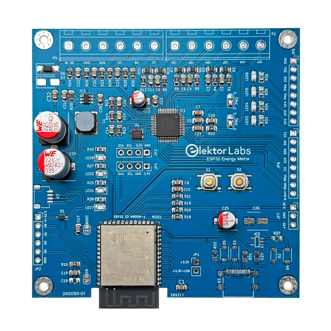
Das Elektor ESP32-Energiemessgerät wurde für die Echtzeit-Energieüberwachung und die Smart Home-Integration entwickelt. Angetrieben durch den ESP32-S3 Mikrocontroller bietet es robuste Leistung mit modularen und skalierbaren Funktionen.
Das Gerät verwendet einen 110/230 VAC auf 12 VAC Abwärtstransformator zur Spannungsabtastung, der eine galvanische Trennung und Sicherheit gewährleistet. Sein kompaktes Platinenlayout umfasst Schraubklemmenblöcke für sichere Verbindungen, einen Qwiic-Anschluss für zusätzliche Sensoren und einen Programmier-Header für die direkte ESP32-S3-Konfiguration. Der Energiezähler ist mit einphasigen und dreiphasigen Systemen kompatibel und somit für verschiedene Anwendungen anpassbar.
Das Energiemessgerät ist einfach einzurichten und lässt sich in Home Assistant integrieren. Er bietet Echtzeitüberwachung, Verlaufsanalysen und Automatisierungsfunktionen. Es liefert genaue Messungen von Spannung, Strom und Leistung und ist damit ein wertvolles Werkzeug für das Energiemanagement in Haushalten und Unternehmen.
Features
Umfassende Energieüberwachung: Erhalten Sie detaillierte Einblicke in Ihren Energieverbrauch für eine intelligentere Verwaltung.
Anpassbare Software: Passen Sie die Funktionalität an Ihre Bedürfnisse an, indem Sie eigene Sensoren programmieren und integrieren.
Smart Home Ready: Kompatibel mit ESPHome, Home Assistant und MQTT für vollständige Smart Home-Integration.
Sicher & Flexibles Design: Funktioniert mit einem 110/230 VAC auf 12 VAC Abwärtstransformator und verfügt über eine vormontierte SMD-Platine.
Schnellstart: Enthält einen Stromwandlersensor und Zugang zu kostenlosen Einrichtungsressourcen.
Technische Daten
Mikrocontroller
ESP32-S3-WROOM-1-N8R2
Energiemess-IC
ATM90E32AS
Statusanzeigen
4x LEDs zur Anzeige des Stromverbrauchs2x programmierbare LEDs für benutzerdefinierte Statusbenachrichtigungen
Benutzereingabe
2x Drucktasten zur Benutzersteuerung
Ausgabe anzeigen
I²C-OLED-Display zur Echtzeit-Anzeige des Stromverbrauchs
Eingangsspannung
12~16 VAC (über einen Abwärtstransformator von 110/230 VAC auf 12 VAC)
Klemmstromsensor
YHDC SCT013-000 (100 A/50 mA) im Lieferumfang enthalten
Smart Home-Integration
ESPHome, Home Assistant und MQTT für nahtlose Konnektivität
Konnektivität
Header für die Programmierung, Qwiic für Sensorerweiterung
Anwendungen
Unterstützt einphasige und dreiphasige Energieüberwachungssysteme
Abmessungen
79,5 x 79,5 mm
Lieferumfang
1x Teilbestückte Platine (SMD-Bauteile sind vormontiert)
2x Schraubklemmenblock-Anschlüsse (nicht montiert)
1x YHDC SCT013-000 Stromwandler
Erforderlich
Netztransformator nicht enthalten
Downloads
Datasheet (ESP32-S3-WROOM-1)
Datasheet (ATM90E32AS)
Datasheet (SCT013-000)
Frequently Asked Questions (FAQ)
Vom Prototyp zum fertigen Produkt
Was als innovatives Projekt zur Entwicklung eines zuverlässigen und benutzerfreundlichen Energiemessgeräts mithilfe des ESP32-S3-Mikrocontrollers begann, hat sich zu einem robusten Produkt entwickelt. Ursprünglich als Open-Source-Projekt entwickelt, zielte das Gerät darauf ab, eine präzise Energieüberwachung, Smart-Home-Integration und mehr zu ermöglichen. Durch sorgfältige Hardware- und Firmware-Entwicklung ist das Energiemessgerät heute eine kompakte, vielseitige Lösung für das Energiemanagement.