
Suchergebnisse für "elektor OR raspberry OR pi OR ruler"
-

Elektor Classics The Ton Giesberts Collection (USB-Stick)
Praxisprojekte aus Analogtechnik, Audiotechnik und darüber hinaus Entdecken Sie eine bemerkenswerte Sammlung mit mehr als 250 Elektronikprojekten, die im Elektor Magazin veröffentlicht und vom renommierten Elektor-Laboringenieur Ton Giesberts sorgfältig ausgewählt wurden. Der USB-Stick vereint eine große Vielfalt an Schaltungen, Entwicklungen und praxisnahen Projektideen, die im Laufe der Jahre von zahlreichen Elektor-Autoren und Ingenieuren erstellt wurden. Das umfangreiche Archiv deckt ein breites Spektrum an Elektronikthemen ab und ist eine wertvolle Wissens- und Inspirationsquelle für Ingenieure, Maker, Studierende und Elektronikbegeisterte. Mehr als 250 ausgewählte Elektor-Projekte Sorgfältig zusammengestellt von Elektor-Ingenieur Ton Giesberts Ideal zum Nachbauen, Experimentieren und Entdecken neuer Ideen Entdecken Sie Jahrzehnte geballter Elektor-Kompetenz in einer umfassenden Projektsammlung. Highlights Q-Watt Audio-Endstufe Fortissimo-100 High-End-Verstärker Pufferplatine für den Raspberry Pi 400 USB-zu-Multiprotokoll-Seriell-Wandler DDS-Funktionsgenerator AC/DC-Leistungsmesser Charge-a-Phone Technische Daten Speicher 8 GB Anschlüsse 1x USB-A1x USB-C Systemvoraussetzungen Rechner geeignet für Adobe Reader ab Version 7.0 Web-Browser
€ 49,95
Mitglieder: € 44,96
-
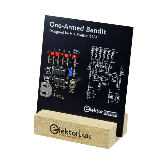
Elektor Labs Elektor Einarmiger Bandit
Ziehen Sie den Hebel nach unten, um die höchste Punktzahl zu erzielen!Dieser Elektor-Schaltungsklassiker aus dem Jahr 1984 zeigt eine spielerische Anwendung von Logik-ICs der CMOS-400x-Serie in Kombination mit LEDs, einer damals sehr beliebten Kombination. Das Projekt imitiert einen Spielautomaten mit rotierenden Ziffern.Das SpielUm das Spiel zu spielen, vereinbaren Sie zunächst die Anzahl der Runden. Spieler 1 betätigt den Schalthebel so lange wie gewünscht und lässt ihn los. Die LEDs zeigen dann die Punktzahl an, die sich aus der Summe der 50-20-10-5 aufleuchtenden Ziffern ergibt. Wenn die Play Again!-LED aufleuchtet, hat Spieler 1 eine weitere, „freie“ Runde. Wenn nicht, ist Spieler 2 am Zug. Die Spieler behalten ihre Punkte im Auge und der Spieler mit der höchsten Punktzahl gewinnt.FeaturesLEDs zeigen den Punktestand anMulti-Player und Play Again!Symbole des Elektor Heritage CircuitGetestet und geprüft von Elektor LabsEdukatives und geekiges ProjektNur Teile mit DurchgangslochLieferumfangPlatineAlle KomponentenHolzständerStücklisteWiderstände (5%, 250 mW)R1,R2,R3,R4 = 100kΩR5,R6,R7,R8,R9,R10 = 1kΩKondensatorenC1 = 4.7nF, 10%, 50V, 5mmC2 = 4.7μF, 10%, 63V, axialC3,C4 = 100nF, 10 %, 50V, Keramik X7R, 5mmHalbleiterLED1-LED6 = rot, 5mm (T1 3/4)IC1 = 74HC4024IC2 = 74HC132SonstigesS1 = Schalter, Kipphebel, 21-mm-Hebel, SPDT, tastendS2 = Schalter, taktil, 24V, 50mA, 6x6mmS3 = Schalter, Schieber, SPDTIC1,IC2 = IC-Sockel, DIP14BT1 = CR2032-Batteriehalteklammer für PlatinenmontageTischständerPCB 230098-1Nicht im Lieferumfang enthalten: BT1 = CR2032-Knopfzellenbatterie
€ 39,95€ 24,95Bestpreis
-

Elektor Digital Raspberry Pi 3 – Basic to Advanced Projects (E-book)
This book is about the Raspberry Pi 3 computer and its use in various control and monitoring applications. The book explains in simple terms and with tested and working example projects, how to configure the Raspberry Pi 3 computer, how to install and use the Linux operating system, and how to write hardware based applications programs using the Python programming language. The nice feature of this book is that it covers many Raspberry Pi 3 based hardware projects using the latest hardware modules such as the Sense HAT, Swiss Pi, MotoPi, Camera module, and many other state of the art analog and digital sensors. An important feature of the Raspberry Pi 3 is that it contains on-board Bluetooth and Wi-Fi modules. Example projects are given in the book on using the Wi-Fi and the Bluetooth modules to show how real-data can be sent to the Cloud using the Wi-Fi module, and also how to communicate with an Android based mobile phone using the Bluetooth module. The book is ideal for self-study, and is intended for electronic/electrical engineering students, practising engineers, research students, and for hobbyists. It is recommended that the book should be followed in the given Chapter order. Over 30 projects are given in the book. All the projects in the book are based on the Python programming language and they have been fully tested. Full program listings of every project are given in the book with comments and full descriptions. Experienced programmers should find it easy to modify and update the programs to suit their needs. The following sub-headings are given for each project to make it as easy as possible for the readers to follow the projects: Project title Description Aim of the project Raspberry Pi type Block diagram Circuit diagram Program listing
€ 29,95
Mitglieder: € 26,96
-

Elektor Labs Elektor Rauscharmes Labornetzteil
Das rauscharme Labornetzteil von Elektor ist ein vollständig analoges, einstellbares, symmetrisches Gerät mittlerer Leistung, das ohne Schalt- oder digitale Komponenten auskommt. Es bietet eine Ausgangsspannung, die zwischen 0 V und ±22 V einstellbar ist, sowie einen Ausgangsstrom, der von 0 A bis 1 A eingestellt werden kann. Da auf jegliche Art von Schalttechnik verzichtet wird, liefert das Design extrem geringes Rauschen. Zur Anzeige beider Ausgangsspannungen und -ströme werden vier kleine analoge Einbauinstrumente mit Drehspulmesswerk verwendet. Die meisten modernen Labornetzgeräte und AC-Adapter arbeiten mit Schaltnetzteiltechnik. Selbst die besten Ausführungen weisen zwangsläufig hochfrequente Restwelligkeit und andere Schaltartefakte am Ausgang auf, die die Prüfung empfindlicher analoger Schaltungen stören und Messungen kleiner Signale beeinträchtigen können. Um dieses Problem zu vermeiden, setzt dieses Konzept auf ein vollständig analoges Netzgerät. Obwohl es weniger effizient ist als vergleichbare Schaltnetzteile, spielt die geringere Effizienz beim Einsatz auf dem Prüfstand kaum eine Rolle und sorgt für sauberere und zuverlässigere Messergebnisse. Da viele analoge Schaltungen eine symmetrische Versorgung benötigen, liefert dieses Design positive und negative Ausgangsspannungen gleicher Höhe. Eine geringfügige Nachjustierung ist möglich, um eventuelle Ungleichgewichte auszugleichen. Selbstverständlich ist auch eine einstellbare Strombegrenzung integriert. Das Kit enthält die für den Aufbau des Netzteils erforderlichen Komponenten, mit Ausnahme der Transformatoren. Technische Daten Ausgangsspannung 0…+22 V, 0, −22 V Ausgangsstrom 0…+1 A, 0…−1 A Rauschen −85 dBV (bei 0,95 A/20 V, B = 22 kHz) −84 dBV (bei 0,95 A/20 V, B > 500 kHz) Restwelligkeit 50 µVRMS (bei 950 mA/20 V, B = 22 kHz, hauptsächlich 100-Hz-Anteil) Lieferumfang 3x Platinen: Regler (PCB-1), Netzfilter (PCB-2) und Transformator (PCB-3) Alle Bauteile mit Ausnahme der Netztransformatoren 4x Drehspulmesswerke Zusätzliche Teile für die Verdrahtung (Drähte, Bananenbuchsen, Kaltgeräte-Netzmodul usw.) Nicht enthalten Die drei Netztransformatoren Ein Gehäuse Stückliste Für die Spannungsregler-Platine (240386-1) Widerstände (250 mW, 1%) R1 = 12 Ω R2, R8, R37, R62 = 1 MΩ R3, R7, R10, R13, R17, R20, R22, R30, R35, R42, R45, R47, R55, R60 = 100 Ω, 600 mW R4, R5 = 4.7 kΩ R6 = 100 kΩ R9, R12, R14, R36, R38, R39, R61, R63, R66, R72, R78, R79 = 10.0 kΩ, 600 mW R11 = 9.76 kΩ, 600 mW R15, R40 = 44.2 kΩ, 600 mW R16, R41, R77 = 1 kΩ R18, R43 = 1.5 kΩ, 1 W, 5% R19, R44 = 470 Ω, 1 W, 5% R21, R46 = 330 Ω, 600 mW R23, R24, R48, R49 = 1.0 Ω, 1 W R25, R50 = 1 kΩ, 1 W, 5% R26, R28, R51, R53 = 1.000 kΩ 0.1%, 15 ppm/C R27, R29, R52, R54 = 10.00 kΩ 0.1%, 15 ppm/C R31, R56 = 1.2 kΩ, 1 W, 5% R32, R57 = 47 kΩ R33, R58 = 270 Ω R34, R59 = 27 kΩ R64, R69 = 12.0 kΩ R65 = 3.0 kΩ, 600 mW R67, R80 = 470 Ω, 600 mW R68, R70 = 6.8 kΩ, 600 mW R71 = 30.0 kΩ,, 600 mW R73, R74, R75, R76 = 10 MΩ P1, P2, P3 = 10 kΩ, 200 mW, 20%, potentiometer, 1 turns, single, lin., panel mount P4, P5 = 500 Ω, 500 mW, 10%, trimmer, 25 turns, 3296Y-1-501LF Bourns P6, P7 = 10 kΩ, 500 mW, 10%, trimmer, 25 turns, 3296Y-1-501LF Bourns Kondensatoren C1 = 100 nF, 50 V, 10%, ceramic X7R, LS 5 mm C2, C3, C6, C7, C30 = 10 µF, 63V, 20%, LS 2.5 mm, 3000hours@105°C C4, C5, C8, C9, C13, C14, C18, C19, C23, C24, C28, C29, C31, C32, C38, C39 = 100 nF, 250 V, 10%, PET, LS 7.5 mm C10, C20 = 47 nF, 100 V, 5%, PET, LS 5 mm C11, C21 = 10 nF, 100 V, 5%, PET, LS 5 mm C12, C22 = 220 µF, 35 V, 20%, 0.024 Ω, LS2.5/3.5 mm, Ir 3.4 A, 2000hours@125°C, polymer C15, C25 = 120 µF, 50 V, 20%, ESR 0.02 Ω, Diam. 10 mm max., LS 5 mm C16, C26 = 15 nF, 100 V, 5%, PET, LS 5 mm C17, C27 = 47 nF, 100 V, 5%, PET, LS 5 mm C33, C34 = 22 µF, 50 V, 20%, LS 2 mm, 10000 hours @ 105°C C35, C36, C44, C45 = 1 µF, 100 V, 10%, LS 5 mm, ceramic X7R C37 = 100 uF, 50 V, 20%. LS 3.5 mm C40, C41, C42, C43, C46, C47, C48, C49 = 1000 µF, 50 V, 20%, LS 5/7.5 mm, Ir 3.32 A, 10000hours@105°C, D 16 mm C50, C51, C52, C53 = 47 nF, 100 V, 10%, ceramic X7R, LS 5 mm Induktivitäten L1, L2 = 4.7 µH, 3.2 A, 0.033 Ω, LS 5 mm, RLB0914-4R7ML Bourns L3 = Commom mode choke, 14.5 mH, 3 A, SSRH24NH-30145 Kemet Halbleiter D1, D2, D3, D4, D5, D9, D10, D11, D15 = BAT85, DO-34 D6, D7, D12, D13 = SR560, DO-201AD D8, D14, D16 = 1N4148, DO-35 D17 = Zenerdiode, 5.6 V, 0.5 W, DO-41 D18, D19 = 1N4004, DO-41 D20, D21 D22, D23 = V30100CI-M3/P, dual common cathode, TO-220 D24 = Zener diode, 30 V, 1 W, DO-41 LED1, LED2 = LED, red, T-1 (3 mm) LED3, LED4 = LED, green, T-1 (3 mm) TVS1, TVS2 = BZW50-33B, R6 T1, T2, T4 = BC337.25, TO-92 T3 = NJW0302G, TO-3P T5, T6, T8 = BC327.25, TO-92 T7 = NJW0281G, TO-3P T9 = BD139, TO-126 (SOT-32) IC1 = LM334Z, TO-92 IC2 = LM4040AIZ-5.0/NOPB, TO-92 (TO-226AA-3) IC3, IC4 = OPA2992IDR, SOIC-8 IC5, IC6 = OPA4992IDR, SOIC-14 IC7 = OPA992IDBVR, SOT-23-5 IC8 = LM339N, DIP-14 IC9 = LM317, TO-220 IC10 = LM337, TO-220 Sonstiges F1, F2 = 5×20 mm fuse, 1.6 A, fast acting HS1, HS2 = Heatsink MC33271 (for T3/T7), 2.7°C/W, PCB mount, height 63.5 mm K1, K4 = 3-way screw terminal block, LS 3.5 mm, max. 1.5 mm² K2, K3 = 3-way screw terminal block, LS 3.5 mm, max. 1 mm² M1, M3 = Moving coil meter, Range 30 V, type 91C4, 45×45 mm M2, M4 = Moving coil meter, Range 1 A, type 91C4, 45×45 mm² RE1 = Relay DPDT,5V, UA2-5NU Verschiedenes 3× 3-way screw terminal block, LS 3.5 mm, max. 1 mm² (for P1, P2, P3) 4× Pin header, 1×2, vertical, pitch 2.54 mm (for LED1, LED2, LED3, LED4) 4× Pin socket, 1×2, vertical. pitch 2.54 mm (for LED1, LED2, LED3, LED4) 2× Heatsink FK222SA220, 20°C/W, PCB mount (for IC9 & IC10) 2× Mica thermal pad for TO-220, 12×18×0.05 mm (for IC9 & IC10) 2× Insulating bushing IB 6, TO-220 (for IC9 & IC10) 2× Ceramic thermal pad, 23×20×2 mm (for T3 & T7) 2× PCB Fuse Holder, for 5×20 mm fuse, 10 A (for F1, F2) 2× Cover for PCB Fuse Holder, transparent (for F1, F2) 2× 2-way screw terminal block, LS 3.5 mm, max. 1 mm² (for M1 & M3) 2× 2-way screw terminal block, LS 3.5 mm, max. 1.5 mm² (for M2 & M4) 8× M3 solder lug, thickness 0.35 mm (for M1…M4) M4 solder lug, thickness 0.35 mm (to connect 4 mm banana connectors) Screened cable, 1 pair, 2×24 AWG/0.22 mm², 1 m (for P1, P2 & P3) IC socket, DIP, 14 contacts (for IC8) M3 washer, plain, steel M3 screw, 16 mm, steel, pan head M3 nut M3 spring washer 50 mm M3 standoff, steel, male-female 12 mm M3 standoff, steel, male-female 10 mm M3 standoff, steel, male-female M3 screw, 8 mm, steel, pan head Für die Netzfilter-Platine (240386-2) Widerstand R1 = 220 kΩ, 1 W, 500 V, 5% Kondensatoren C1, C2 = 470 nF, 305 VAC, Class X2, 11 × 27 mm max., LS 15/22.5 mm C3, C4, C5, C6 = 2.2 nF, 300 VAC, Class Y2, 13 × 4 mm, LS 10 mm, PP Induktivitäten L1, L2 = Common-mode choke, 6.8 mH, 1.7 A, TDK B82732R2172B030 Halbleiter MOV1 = TVS varistor, 300 VAC, S14K300 (230 VAC, B72214S0301K101) and SK14K150 (150 VAC, B72214S0151K101) Sonstiges K1, K2 = 3-way screw terminal block, LS 7.62 mm F1 = Time-delay fuse, 0.5 A (230 VAC) or 1 A (115 VAC) Verschiedenes 1× Fuse holder, 5×20 mm, 10 A, 500 VAC 1× Transparent fuse cover 4× 10 mm M3 standoff, steel, male–female 4× M3 screw, 8 mm, steel, pan head 4× M3 nut Für die Transformator-Platine (240386-3) Widerstände R1, R2 = 2.7 kΩ, 600 mW, 1% R3 = 10.0 kΩ, 600 mW, 1% Kondensator C1 = 220 µF, 50 V, 20%, Ø10 mm, LS 5 mm, 4000 h @ 105°C Transformatoren (nicht im Lieferumfang dieses Kits enthalten!) TR1, TR2, TR3 = 2×7 V, 25 VA, PCB-mounted toroid, 70060K Talema Halbleiter D1–D4 = 1N4148, DO-35 D5, D6 = 1N4004, DO-41 D7 = Zener 5.6 V, 1.3 W, DO-41 LED1 = LED, red, T-1 (3 mm) IC1, IC2 = MOC8021M, CTR ≥ 1000%, DIP-6 Sonstiges F1, F2, F3 = 160 mA time-delay fuse (230 VAC) or 315 mA time-delay fuse (115 VAC) K1 = 2-way screw terminal block, LS 7.62 mm K2 = 3-way screw terminal block, LS 3.5 mm, max 1.5 mm² K3, K4 = 3-way screw terminal block, LS 3.5 mm, max 1 mm² RE1, RE2 = Relay DPDT, 5 A/250 VAC / 24 VDC Verschiedenes 1× Pin header 1×2, pitch 2.54 mm + matching socket for LED1 3× Fuse holder 5 × 20 mm, 10 A, 500 VAC + transparent cover 3× M4 screw, 8 mm, pan head + washer for TR1-TR3 8× M3 screw, 8 mm, pan head + nut + washer 8× 10 mm M3 standoff, steel, male–female 2× IC socket, DIP-6 for IC1 & IC2 Weitere Bauteile 1 m red insulated wire, stranded, 1.5 mm² 0.5 m blue insulated wire, stranded, 1.5 mm² 0.5 m black insulated wire, stranded, 1.5 mm², 0.5 m 2 m red insulated wire, stranded, D 0.56 mm (0.25 mm²) 2 m black insulated wire, stranded, D 0.56 mm (0.25 mm²) 0.5 m Multicore Cable, Flexible, 3 Core, 0.75 mm² (24 x 0.2 mm) Red banana socket Black banana socket Blue banana socket Green banana socket IEC Power Entry Module with switch, IEC C14 3 crimp terminals, FASTON, 4.75 x 0.81 mm 3 knobs Links Elektor Labs JumpStarter Page Artikel (Teil 1) Artikel (Teil 2)
€ 249,00
Bestpreis
-
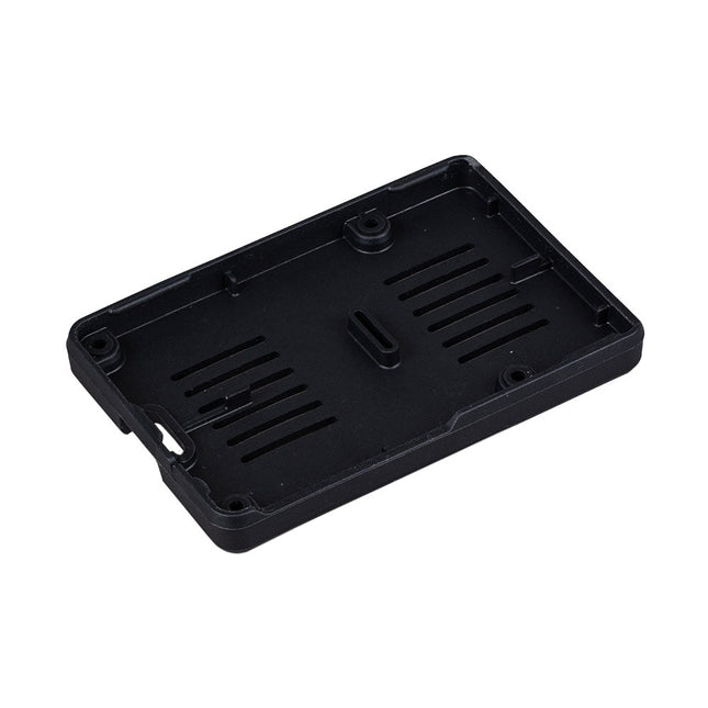
Raspberry Pi Foundation Bumper für Raspberry Pi 5
Der Raspberry Pi Bumper ist eine aufsteckbare Silikonabdeckung, die die Unterseite und die Kanten des Raspberry Pi 5 schützt. Features Einteiliger flexibler Bumper aus Silikonkautschuk Ermöglicht einfachen Zugriff auf den Power-Button Montagelöcher bleiben unter dem Bumper zugänglich Downloads Datasheet
€ 3,50€ 1,95Bestpreis
-
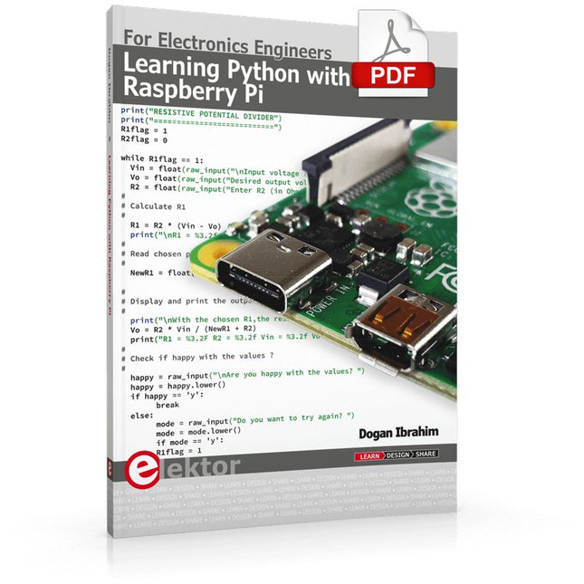
Elektor Digital Learning Python with Raspberry Pi (E-book)
This book is about teaching the Python programming language using the Raspberry Pi 4 computer. The book makes an introduction to Raspberry Pi 4 and then teaches Python with the topics: variables, strings, arrays, matrices, tuples, lists, dictionaries, user functions, flow of control, printing, keyboard input, graphics, GUI, object oriented programming and many more topics. The book is aimed for beginners, students, practising engineers, hobbyists, and for anyone else who may want to learn to program in Python. The book includes many example programs and case studies. All the example programs and case studies have been tested fully by the author and are all working. The example programs aim to teach the various programming concepts of Python. The case studies cover the use of Python in the analysis and design of electronic circuits. Some of the case study topics are: Resistor colour code identification Resistive potential divider circuits Resistive attenuator design Zener diode voltage regulator design RC and RLC transient circuits Circuit frequency response Saving data on external memory stick Mesh and node circuit analysis using matrices Resonance in RLC circuits Transistor Biasing analysis Transistor amplifier design Design of active filters Interfacing hardware with GPIO, I²C and SPI Using Wi-Fi with Python and TCP/IP and UDP programs Using Bluetooth from Python Full program listings of all the programs used in the book are available at the Elektor website of the book. Readers should be able just to copy and use these programs in their Raspberry Pi projects without any modifications.
€ 32,95
Mitglieder: € 29,66
-
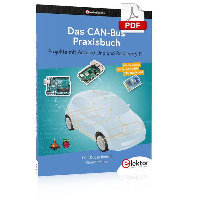
Elektor Digital Das CAN-Bus Praxisbuch (PDF)
Projekte mit Arduino Uno und Raspberry Pi In diesem Buch werden Anwendungen von Arduino Uno und Raspberry Pi 4 in praxisnahen Projekten auf Basis von CAN-Bus detailliert beschrieben. Durch den Einsatz von entweder Arduino Uno oder Raspberry Pi in Verbindung mit handelsüblichen CAN-Bus-Schnittstellenmodulen werden die Entwicklung, Fehlersuche und Fehlerbeseitigung sowie die Überprüfung von Projekten auf CAN-Bus-Basis erheblich erleichtert. Dieses Buch richtet sich an jeden, der mehr über den CAN-Bus lernen möchte und mit den Grundlagen der Elektronik vertraut ist. Hilfreich ist auch, Erfahrungen mit den Programmiersprachen C und Python sowie mit der Programmierung von Arduino Uno unter Verwendung seiner IDE und von Raspberry Pi zu haben. Das Buch ist eine nützliche Informationsquelle und ein Nachschlagewerk für jeden, der Antworten auf eine oder mehrere der folgenden Fragen sucht: Welche Bussysteme stehen für die Automobilindustrie zur Verfügung? Was sind die Grundprinzipien des CAN-Bus? Welche Arten von Frames (oder Datenpaketen) stehen in einem CAN-Bussystem zur Verfügung? Wie können Fehler in einem CAN-Bussystem erkannt werden, und wie zuverlässig ist ein CAN-Bussystem? Welche Arten von CAN-Bus-Controllern gibt es? Was sind die Funktionsprinzipien des MCP2515 CAN-Bus-Controllers? Wie kann ich ein CAN-Bus-Projekt mit Arduino Uno realisieren? Wie kann ich Arduino- oder Raspberry Pi-CAN-Bus-Projekte mit 2 und 3 Knoten erstellen? Wie kann ich die Daten auf dem CAN-Bus analysieren? Wie kann ich ein CAN-Bus-Projekt mit Raspberry Pi ausführen?
€ 29,80
Mitglieder: € 26,82
-
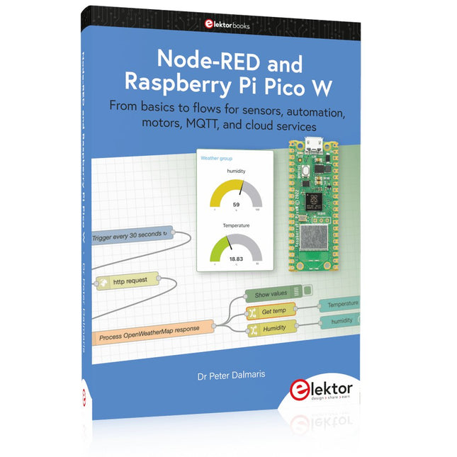
Elektor Publishing Node-RED and Raspberry Pi Pico W
From basics to flows for sensors, automation, motors, MQTT, and cloud services This book is a learning guide and a reference. Use it to learn Node-RED, Raspberry Pi Pico W, and MicroPython, and add these state-of-the-art tools to your technology toolkit. It will introduce you to virtual machines, Docker, and MySQL in support of IoT projects based on Node-RED and the Raspberry Pi Pico W. This book combines several elements into a platform that powers the development of modern Internet of Things applications. These elements are a flow-based server, a WiFi-enabled microcontroller, a high-level programming language, and a deployment technology. Combining these elements gives you the tools you need to create automation systems at any scale. From home automation to industrial automation, this book will help you get started. Node-RED is an open-source flow-based development tool that makes it easy to wire together devices, APIs, and online services. Drag and drop nodes to create a flowchart that turns on your lights at sunset or sends you an email when a sensor detects movement. Raspberry Pi Pico W is a version of the Raspberry Pi Pico with added 802.11n Wi-Fi capability. It is an ideal device for physical computing tasks and an excellent match to the Node-RED. Quick book facts Project-based learning approach. Assumes no prior knowledge of flow-based programming tools. Learn to use essential infrastructure tools in your projects, such as virtual machines, Docker, MySQL and useful web APIs such as Google Sheets and OpenWeatherMap. Dozens of mini-projects supported by photographs, wiring schematics, and source code. Get these from the book GitHub repository. Step-by-step instructions on everything. All experiments are based on the Raspberry Pi Pico W. A Wi-Fi network is required for all projects. Hardware (including the Raspberry Pi Pico W) is available as a kit. Downloads GitHub
€ 49,95
Mitglieder: € 44,96
-

Elektor Digital Elektor July/August 2023 (PDF)
Elektor GREEN and GOLD members can download their digital edition here. Not a member yet? Click here. Rotary Dial Phone as Remote ControlTo Switch On the Lights, Dial 1; For the Coffee Maker, Dial 2 GPS-Based Speed MonitorNo More Speeding Tickets RGB Stroboscope with ArduinoA Colorful Adaptation of a Useful Instrument Wireless Emergency Push ButtonEnhanced Safety with LoRa Starting Out in ElectronicsFollow the Emitter Arbitrary, Independent Hysteresis Levels for Comparatorswith Simulations, Spreadsheets and Algebra ESP32-Based Impedance AnalyzerSimple, Low-Part-Count, and Inexpensive! HomeLab ToursEncouraging DIY The MCCAB Arduino Nano Training BoardAll-in-One Hardware for the “Microcontrollers Hands-On Course” From Life’s ExperienceModern Luddism Sensor 101: The DS18B20 Temperature SensorConnection to the 1-Wire Bus Is Matter the Thread to Save the Smart Home?New Standards to Simplify the Smart Home A Matter of CollaborationDeveloping with the Thing Plus Matter Board and Simplicity Studio Infographics: IoT and Sensors Matter, ExpressLink, Rainmaker — What Is This All About?Q&A with Amey Inamdar, Technical Marketing Director at Espressif Selecting Microcontroller Dev Kits for IoT and IIoT ApplicationsAn Introductory Guide Capacitors Do Not Always Behave Capacitively! An NTP Clock with CircuitPythonWhy Should You Use This Programming Language? Build a Cool IoT DisplayWith the Phambili Newt The HB100 Doppler Motion SensorTheory and Practice A Bare-Metal Programming Guide (Part 1)For STM32 and Other Controllers Siglent SDM3045X Multimeter Microprocessors for Embedded SystemsPeculiar Parts, the Series Microcontroller Documentation Explained (Part 3)Block Diagrams and More Low-Power LoRa Weather StationBuild a long-range weather station by yourself Transverter for the 70 cm Band Climate Calling EngineersMove Fast and Fix Things Hexadoku
€ 7,50
-

Elektor Digital Raspberry Pi 5 for Radio Amateurs (E-book)
Program and Build Raspberry Pi 5 Based Ham Station Utilities with the RTL-SDR The RTL-SDR devices (V3 and V4) have gained popularity among radio amateurs because of their very low cost and rich features. A basic system may consist of a USB based RTL-SDR device (dongle) with a suitable antenna, a Raspberry Pi 5 computer, a USB based external audio input-output adapter, and software installed on the Raspberry Pi 5 computer. With such a modest setup, it is possible to receive signals from around 24 MHz to over 1.7 GHz. This book is aimed at amateur radio enthusiasts and electronic engineering students, as well as at anyone interested in learning to use the Raspberry Pi 5 to build electronic projects. The book is suitable for both beginners through experienced readers. Some knowledge of the Python programming language is required to understand and eventually modify the projects given in the book. A block diagram, a circuit diagram, and a complete Python program listing is given for each project, alongside a comprehensive description. The following popular RTL-SDR programs are discussed in detail, aided by step-by-step installation guides for practical use on a Raspberry Pi 5: SimpleFM GQRX SDR++ CubicSDR RTL-SDR Server Dump1090 FLDIGI Quick RTL_433 aldo xcwcp GPredict TWCLOCK CQRLOG klog Morse2Ascii PyQSO Welle.io Ham Clock CHIRP xastir qsstv flrig XyGrib FreeDV Qtel (EchoLink) XDX (DX-Cluster) WSJT-X The application of the Python programming language on the latest Raspberry Pi 5 platform precludes the use of the programs in the book from working on older versions of Raspberry Pi computers.
€ 32,95
Mitglieder: € 29,66
-

Elektor Digital Elektor September/October 2022 (PDF)
Elektor GREEN and GOLD members can download their digital edition here. Not a member yet? Click here. electronica fast forward 2022 Start- & Scale-Up AwardsPreparations Speeding Up! Bluetooth Low Energy with ESP32-C3 and ESP32You Don’t Always Need to Choose Wi-Fi! Bluetooth Low Energy SnifferHacking a makerdiary nRF52840 MDK USB Dongle Magic RGB LED CubeHardware Design Around an RP2040 Auto On/Off for Solder Paste Compressor Elektor Video ContentLivestreams, Webinars, and Courses for Engineers and Pro Makers Bicycle ElectrificationHands-On with an E-Bike Retrofit Kit Starting Out in ElectronicsMultiplying Voltages From Life’s ExperienceSidelines Teensy 4.0Why Is This Board So Fast? Audio Power Amplifier Simulation with TINAThe Try-Before-You-Build Approach Develop and Operate Your LoRaWAN IoT NodesSample Chapter: Dragino LHT65, LDS01, and LDS02 LoRaWAN Modules Err-lectronicsCorrections, Updates and Readers’ Letters 5G Just for MeGaining Complete Control of 5G Deployments with Private Cellular Networks Infographics 7-8/2022 How Does My Device Learn to Transmit?Applications with Wi-Fi Interfaces Smartphones are the Heart of the IoT Audio Spectrum Analyzer with DekatronsA New Way to Use Vintage Tubes Sending Data to TelegramGet It Done with an ESP32 and a Few Parts A Fliege Notch Filter for Audio MeasurementsMake Better Measurements with a Notch Filter CO2 Meter TeardownIs It Hackable for Your Projects? PUT-ting It All TogetherThe Programmable Unijunction Transistor Explained Round Touchscreen for Raspberry PiHyperPixel 2.1 Round from Pimoroni Remote Sensing with Connection Loss DetectionUsing nRF24L01+ Modules Digital FM Receiver with Arduino and TEA5767Stayed Tuned with an Arduino Nano Changing an OLED Interface from SPI to I²C HomeLab ToursA Hobby Does Not Retire A Decade of Ethics in ElectronicsTessel Renzenbrink Reflects on the Digital Society and More HexadokuThe Original Elektorized Sudoku
€ 7,50
-

Elektor Classics The Elektor Circuit Collection 2026 (USB-Stick)
3K5 bemerkenswerte Schaltungen (1975-2026) Dieser USB-Stick enthält über 3.500 bemerkenswerte Schaltungen aus allen Bereichen der Elektronik (Audio & Video, Spiel & Hobby, Haus & Hof, Prozessor & Controller, Messen & Testen, PC & Peripherie, Stromversorgung & Ladetechnik), die seit 1975 in der Zeitschrift Elektor veröffentlicht wurden. Mit der Artikelsuchfunktion können Sie im Volltext nach bestimmten Inhalten suchen. Die Ergebnisse werden immer als vorformatierte PDF-Dokumente angezeigt. Mit dem Adobe Reader können Sie sowohl in den Artikeln blättern als auch einzelne Wörter und Begriffe über die integrierte Suchfunktion des Programms finden. Bitte beachten Sie, dass zwischen 2014 und 2022 keine Summer Circuits-Ausgaben veröffentlicht wurden und diese Jahre daher nicht im Verzeichnis enthalten sind. Technische Daten Speicher 16 GB Anschlüsse 1x USB-A1x USB-C
€ 49,95
Mitglieder: € 44,96


