
Suchergebnisse für "support"
-

JOY-iT Joy-Pi Advanced Entwicklungsplattform (inkl. Raspberry Pi 4, 8 GB)
Der Joy-Pi Advanced ist ein kompaktes und leistungsstarkes Gerät, welches Ihnen ermöglicht, Ihre Projekte schnell und einfach zu realisieren. Egal, ob Sie bereits viel Erfahrung haben, oder noch so gut wie gar keine – mit dem Joy-Pi Advanced können Sie Ihrer Kreativität freien Lauf lassen. Dank der Kompatibilität mit einer Vielzahl von Plattformen, einschließlich Raspberry Pi, Raspberry Pi Pico, Arduino Nano, BBC micro:bit und NodeMCU ESP32, können Sie einfach und schnell auf Ihre bevorzugte Plattform zugreifen. Darüber hinaus bietet der Joy-Pi Advanced mehr als 30 Stationen, Lektionen und Module, die Ihnen eine unbegrenzte Vielzahl an Möglichkeiten bieten, um Ihre Projekte zu realisieren. Mit der eigenentwickelten Lernzentrale, können Sie nicht nur Ihre Fähigkeiten verbessern, sondern auch neue Projekte erstellen. Die Lernzentrale bietet eine Fülle an Informationen und Tutorials, die Sie Schritt für Schritt durch Ihre Projekte führen. Joy-Pi Advanced zeichnet sich insbesondere durch seine intelligenten Schaltereinheiten aus, die eine erweiterte Nutzung der verfügbaren Pins erlauben. Dabei sind insgesamt drei Schaltereinheiten integriert, jede mit 12 einzelnen Schaltern ausgestattet, die für eine präzise Steuerung der verbundenen Sensoren und Module sorgen. Dieses System löst das bekannte Problem der begrenzten Pin-Anzahl, das bei herkömmlichen Mikrocontrollern auftritt. Die Schaltereinheiten ermöglichen es Ihnen, eine Vielzahl von Sensoren und Modulen parallel zu betreiben, indem sie einzeln ein- und ausgeschaltet werden können. Dadurch wird eine Mehrfachbelegung der Pins simuliert, die es Ihnen ermöglicht, die volle Leistungsfähigkeit Ihrer Projekte auszuschöpfen, ohne Kompromisse bei der Funktionalität eingehen zu müssen. Durch der Kombination von innovativen Adapterplatinen und dem micro:bit-Slot erreicht man eine nahtlose Kompatibilität mit einer Vielzahl von Mikrocontrollern wie Raspberry Pi Pico, NodeMCU ESP32, micro:bit und Arduino Nano. Die speziell entwickelten Adapterplatinen sind so konzipiert, dass sie perfekt auf den jeweiligen Mikrocontroller abgestimmt sind. Durch das Aufstecken des Mikrocontrollers auf die passende Adapterplatine und das anschließende Einstecken in den micro:bit-Slot wird der Joy-Pi Advanced schnell und unkompliziert mit den unterschiedlichen Mikrocontrollern kompatibel. Dies ermöglicht eine nahtlose Integration Ihrer bevorzugten Plattform und die Möglichkeit, die Stärken der verschiedenen Mikrocontroller in Ihren Projekten zu kombinieren. Auf diese Weise können Sie sich voll und ganz auf Ihre kreativen Projekte konzentrieren, ohne sich Gedanken über die Kompatibilität verschiedener Mikrocontroller machen zu müssen. Der Joy-Pi Advanced vereinfacht den Entwicklungsprozess und gibt Ihnen die Möglichkeit, Ihre Projekte flexibel und individuell zu gestalten. Features Hochintegrierte Entwicklungsplattform & Lernzentrale Schnelles, einfaches & kabelloses Kombinieren von verschiedensten Sensoren & Aktoren Einbaumöglichkeit für Raspberry Pi 4 Kompatibel mit verschiedensten Mikrocontrollern Eigenentwickelte, didaktische Lernplattform für Raspberry Pi & Windows Technische Daten Kompatibel mit Raspberry Pi 4, Arduino Nano, NodeMCU ESP32, BBC micro:bit, Raspberry Pi Pico Verbaute Sensoren, Aktoren & Komponenten 39 Lernplattform Über 40 Einträge in der Wissensdatenbank, 10 Projekte, 10 Lernaufgaben, 14 Visionen Displays 7-Segment Display, 16x2 Display, 1,8“ TFT Display, 0,96“ OLED Display, 8x8 RGB Matrix Sensoren DS18B20, Schock-Sensor, Hall-Sensor, Barometer, Sound-Sensor, Gyroskop, PIR-Sensor, Lichtschranke, NTC, Lichtsensor, 6x Touchsensor, Farb-Sensor, Ultraschall-Abstandssensor, DHT11 Temperatur- & Feuchtigkeitssensor Steuerung Joystick, 5x Schalter, Potentiometer, Drehencoder, 4x4 Button-Matrix, Relais, PWM-Lüfter Motoren Servo-Schnittstelle, Schrittmotor-Schnittstelle, Vibrationsmotor Mess- und Wandelmodule Analog-Digital Converter, Pegelwandler, Voltmeter, Variable Spannungsversorgung Sonstige Komponenten RTC Echtzeituhr, Buzzer, EEPROM-Speicher, Infrarot-Empfänger, Breadboard, RFID-Lesegerät Adapterboards Adapter für NodeMCU ESP32, Arduino Nano & Raspberry Pi Pico, Boardconnectoren für Raspberry Pi & Externe Boards Elektronische Komponenten Infrarot-Fernbedienung, RFID-Chip, RFID-Karte, 6x Krokodilklemmen, microSD-Karten-Lesegerät, Servomotor, Schrittmotor, 32 GB microSD-Karte Bauteile 40x Widerstände, 3x grüne LEDs, 3x gelbe LEDs, 3x rote LEDs, 1x Transistor, 5x Buttons, 1x Potentiometer, 2x Kondensatoren Weiteres Zubehör Schraubensortiment, Schraubendreher, Zubehör-Aufbewahrungstasche, Netzgerät & Netzkabel, Servohalterung Stromversorgung Verbautes Netzgerät: 36 W, 12 V, 3 A Gehäuseanschluss: Kleingeräte-Stecker C8 Spannungsausgänge 12 V, 5 V, 3,3 V, Variabler Spannungsausgang (2-11 V) Ausgeführte Datenbusse & Signalausgänge I²C, SPI, Analog-Digital-Wandler Batterie (RTC) CR2032 Abmessungen 327 x 200 x 52 mm Inbegriffen Raspberry Pi 4 (8 GB RAM) Downloads Joy-Pi Website Datenblatt Anleitung
€ 469,00
Bestpreis
-

Elektor Digital Microcontroller Basics (E-book)
Microcontrollers have become an indispensable part of modern electronics. They make things possible that vastly exceed what could be done previously. Innumerable applications show that almost nothing is impossible. There’s thus every reason to learn more about them, but that raises the question of where to find a good introduction to this fascinating technology. The answer is easy: this Microcontroller Basics book, combined with the 89S8252 Flash Board project published by Elektor Electronics. However, this book offers more than just a basic introduction. It clearly explains the technology using various microcontroller circuits and programs written in several different programming languages. Three microcontrollers from the 8051 family are used in the sample applications, ranging from the simple 89C2051 to the AN2131, which is designed to support USB applications. The programming tools include assemblers, Basic-52 and BASCOM-51, and several C compilers. Every reader can thus find the programming environment most suitable to his or her needs. In the course of the book, the reader gradually develops increased competence in converting his or her ideas into microcontroller circuitry. All of the sample programs can be downloaded from the Elektor Electronics website or the author’s website. That has the added advantage that the latest versions are always available.
€ 19,95
Mitglieder: € 17,96
-

Édition spéciale : Les capteurs météorologiques et environnementaux
Construisez votre station météo idéale ou explorez les données environnementales avec le monde entier. Avec de nombreux projets pratiques pour Arduino, Raspberry Pi, NodeMCU, ESP32 et autres cartes de développement. Les stations météo jouissent d’une grande popularité depuis des décennies. Tous les magazines d’électronique, qu’ils soient récents ou non, ont publié et publient régulièrement des articles sur la construction d’une station météo. Au fil des années, elles sont devenues de plus en plus sophistiquées et peuvent aujourd’hui être entièrement intégrées dans la maison intelligente. Ceci implique toutefois souvent une fidélité à un fabricant de produits de marque (coûteux) pour tous les composants. Cependant, avec votre propre station météo, vous pouvez facilement suivre le rythme et même capturer des relevés que les appareils commerciaux ne peuvent pas réaliser. Le plaisir ne manque pas : vous développerez de manière ludique vos connaissances en électronique, en cartes de développement de microcontrôleurs modernes et en langages de programmation. Pour moins de dix euros, vous pouvez collecter des données environnementales initiales et étendre votre système au fur et à mesure que votre intérêt grandit. Dans ce numéro Sur la route du vent et de la météo Écran météo OpenWeatherMap à affichage fluorescent Les composés organiques volatils dans l‘air que nous respirons Travailler avec les capteurs MQ : mesurer le monoxyde de carbone Détecteur de CO2 avec connexion IdO vers ThingSpeak Un arrosage automatique pour vos plantes Un climat intérieur sain : la température et l‘humidité de l‘air sont importants Thermomètre avec tubes Nixie Une maison météo rétro pour toute la famille Mesurez la pression atmosphérique et la température avec précision Un détecteur de coups de soleil Capteur maison pour la durée d‘ensoleillement Le smartphone l‘indique : brouillard ou bonne visibilité ? Détecter les tremblements de terre Les niveaux des cours d‘eau et des réservoirs Évaluer la valeur du pH de l’eau Détecter les rayonnements radioactifs Avec le GPS, vous savez où se trouve votre capteur Enregistrer les fichiers journaux avec horodatage sur des cartes SD LoRaWAN, The Things Network et ThingSpeak Exploiter la passerelle LoRaWAN pour le TTN Affichage géant à led avec prévisions météo
€ 15,50
Mitglieder: € 13,95
-

Sensepeek Sensepeek 6023 SQ350 (350 MHz Freihand-Oszilloskopsonde)
Die Freihandsonden der SQ-Serie von Sensepeek haben einen niedrigeren Schwerpunkt, was sie im Vergleich zur ursprünglichen Freihandsonde der SP-Serie noch stabiler macht. Alle Sonden der SQ-Serie sind außerdem isoliert und können wie jede herkömmliche Sonde in der Hand verwendet werden, ihr volles Potenzial wird jedoch bei freihändigen Messungen genutzt. Die Oszilloskopsonden der SQ-Serie umfassen außerdem mehr Erdungsoptionen, verfügen über einen Sondenspitzenschutz, ein längeres Kabel und unterstützen Oszilloskope mit automatischer Skalierung (10:1). Alle beliebten Funktionen der freihändigen Messung, der austauschbaren Prüfnadel mit feiner Gewindespitze und der farbcodierten Kabelhalter sowie des minimalistischen Designs bleiben erhalten und machen herkömmliche Handsonden überflüssig. Sowohl Länge als auch Gewicht der SQ-Sonden sind perfekt ausbalanciert für die Verwendung mit PCBite-PCB-Haltern und Grundplatten, die für die Freisprechfunktion unerlässlich sind. Features Passiver 10:1-Tastkopf mit Unterstützung für Oszilloskope mit automatischer Skalierung Gefederte Prüfnadel für Feinabstandsmessungen Mehrere Bodenoptionen Farbcodierte Kabelhalter Schutz der Sondenspitze Isoliert, kann in der Hand verwendet werden Verbesserter Sondenhalter für freihändige Messungen bei Verwendung mit PCBite-Leiterplattenhaltern Lieferumfang 1x SQ350 350 MHz Sonde mit federnder Prüfnadel 1x SQ-Sondenhalter für freihändige Messungen 1x Prüfhaken mit abnehmbaren Kabeln (5 cm und 10 cm) für bequemen Erdungsanschluss 1x Krokodilkabel für bequemen Erdungsanschluss 1x Standard-Erdungsfeder für Handmessungen bei Nennbandbreite 1x Einzigartige Erdungsfeder für völlig freihändige Messungen bei Nennbandbreite 1x Set farbcodierte Kabelhalter (4 Farben) 1x Tastspitzenschutz 1x Zusätzliche Prüfnadel Downloads Benutzerhandbuch SQXX0 Rev1.1
€ 105,91
-

Elektor Digital Elektor Special: Power Supplies and Batteries (PDF)
Whatever the methods or even then financial means you have to make your circuits work, the power supply should rank high if not Number One in your considerations. The design block simply called “power supply” is hugely underrated both in electronics creation and repair. Yet, the “PSU” has enormous diversity and comes in wildly differing guises like AC/DC, generator, battery (rechargeable or not), PV panel, benchtop, linear or switch-mode, to mention but a few. The output ranges are also staggering like nano-amps to kiloamps and the same for voltages.This special covers the features and design aspects of power supplies.ContentsBasics Battery ManagementWhat to be aware of when using (Lithium) batteries. Fixed-Voltage Power Supply using Linear RegulatorsThe best result right after batteries. Light Energy HarvestingA small solar panel is used in an energy harvesting project to manage and charge four AAA cells. Mains Powered Adapter DesignBasic circuits and tips for transformers, rectification, filtering and stabilization. LM317 Soft StartThe high inrush current pulse should be avoided. Controllable RectifiersSome suggestions to keep the power loss in the linear regulator as low as possible. Components Worksheet: The LM117 / LM217 / LM317 Voltage Regulators SupercapsLow voltage but lots of current… or not? Reviews JOY-iT RD6006 Benchtop Power Supply Kit Siglent SDL1020X Programmable DC Electronic Load Projects Balcony Power PlantDIY solar balcony = speedy payback! DIY LiPo Supercharger KitFrom handcrafted to mass market Dual-Anode MOSFET ThyristorFaster and less wasteful than the old SCR Battery JuicerDo not throw away, squeeze! High-Voltage Power Supply with Curve TracerGenerate voltages up to 400 V and trace characteristics curves for valves and transistors High Voltage Supply for RIAAFor RIAA tube preamps and other applications. MicroSupplyA lab power supply for connected devices Phantom Power Supply using Switched CapacitorsVoltage tripler using three ICs The SMPS800RE Switch-Mode Supply for the Elektor Fortissimo-100Reliable, light and affordable Soft Start for PSUBe nice to your power supply – and its load UniLab 20-30 V, 3 A compact switch-mode lab power supply Tips Soft Start for Step-Down Switching Regulators Low Loss Current Limit Powerbank Surprise A Virtual Ground Battery Maintainer Battery Pack Discharger Connecting Voltage Regulators in Parallel
€ 11,95
Mitglieder: € 10,76
-
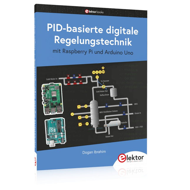
Elektor Publishing PID-basierte digitale Regelungstechnik mit Raspberry Pi und Arduino Uno
Der Arduino Uno ist ein Open-Source-Mikrocontroller-Entwicklungssystem, das Hardware, eine integrierte Entwicklungsumgebung (IDE) und eine Vielzahl von Bibliotheken umfasst. Es wird von einer riesigen Gemeinschaft von Programmierern, Elektronikern, Enthusiasten und Akademikern unterstützt. Insbesondere die Bibliotheken erleichtern die Programmierarbeit und reduzieren die Entwicklungszeiten, da sie das Erstellen von Programmen erheblich erleichtern. Der Raspberry Pi 4 kann in vielen Projekten wie Audio- und Videoanwendungen, aber auch in Industriesteuerungen, Robotik, Spielen usw. eingesetzt werden. Dazu bietet er auch WiFi- und Bluetooth-Fähigkeiten, wodurch er sich zudem hervorragend für internetbasierte Steuerungs- und Überwachungsanwendungen eignet. In diesem Buch werden sowohl der Raspberry Pi 4 als auch der Arduino Uno in PID-basierten automatischen Steuerungsanwendungen eingesetzt. Nach einer grundlegenden Theorie der Regelsysteme werden funktionierende und getestete Projekte zur Steuerung realer Systeme mit PID-Reglern vorgestellt. Die Open-Loop-Eigenschaften, die Abstimmung der PID-Parameter und das Closed-Loop-Zeitverhalten der Systeme werden zusammen mit Blockdiagrammen, Schaltplänen und PID-Regelalgorithmen ausführlich diskutiert. Vollständige Programme für den Raspberry Pi und den Arduino Uno runden die im Buch vorgestellten Projekte ab. Die Regelsysteme können problemlos auch auf andere Projekte angewendet werden und die für den Raspberry Pi 4 angegebenen Programme sollten auch mit anderen Modellen der Raspberry Pi-Familie reibungslos funktionieren. Das Buch behandelt folgende Themen: Steuer- und Regelsysteme Analoge und digitale Sensoren Übertragungsfunktionen und zeitkontinuierliche Systeme Systemantwortfunktionen erster und zweiter Ordnung Zeitdiskrete digitale Systeme Zeitkontinuierliche PID-Regler Zeitdiskrete PID-Regler Zweipunkt-Temperaturregelung mit Raspberry Pi und Arduino Uno PID-basierte Temperaturregelung mit Raspberry Pi und Arduino Uno Motorsteuerung mit Raspberry Pi und Arduino Uno Wasserstandsregelung mit Raspberry Pi und Arduino Uno PID-basierte LED-Helligkeitsregelung mit Raspberry Pi und Arduino Uno
€ 39,80
Bestpreis
-

FNIRSI FNIRSI HS-03 Kabelloser Lötkolben
Der kabellose Lötkolben FNIRSI HS-03 vereint Mobilität mit präziser Temperaturregelung – ideal für Elektronikreparaturen, SMD-Lötarbeiten und den mobilen Einsatz. Dank eines austauschbaren 2600-mAh-Akkus, schneller Aufheizzeit und Unterstützung für USB-C-Stromversorgung bietet er flexible und zuverlässige Leistung, ganz gleich, wo Sie arbeiten. Features Austauschbarer 2600-mAh-Akku für kabellosen Betrieb Dualer Stromversorgungsmodus: Akku oder USB-C Schnelles Aufheizen: Schmilzt Lötzinn in nur 7 Sekunden Temperaturbereich: 100–450°C PID-Temperaturregelung für konstante Hitze 5 voreingestellte Temperaturen für schnelle Anpassungen 0,96"-IPS-Display zur Echtzeitüberwachung Automatischer Schlaf- und Standby-Modus zum Energiesparen F210-Lötspitzen für präzises Arbeiten Kompaktes, ergonomisches Design mit Silikongriff Technische Daten Betriebsspannung 5 V Temperaturbereich 100–450°C Display 0,96"-IPS-HD-Farbbildschirm Lötspitze F210 Akku 18650 Li-Ion (2600 mAh) Leistung 10 W (max.) Stromversorgung USB-C Gewicht 134 g Lieferumfang 1x FNIRSI HS-03 Lötkolben mit integriertem Akku 3x Lötspitzen: 1x K-Spitze (Messerform), 1x I-Spitze (extra spitz), 1x IS-Spitze (gebogen/hakenförmig) 1x Schutzkappe 1x Schraubendreher 1x USB-Kabel 1x Aufbewahrungstasche 1x Manual Downloads Manual Firmware V1.2.0
€ 64,95
Bestpreis
-

Elektor Digital Elektor Special: Arduino Shields (PDF) EN
Make your project dreams come true: an odometer for the hamster wheel, a fully automatic control of your ant farm with web interface, or the Sandwich-O-Mat – a machine that toasts and grills sandwiches of your choice. With the Arduino and the DIY or Maker movement, not only did entry into microcontroller programming become child's play, but a second development also took place: Resourceful developers brought small boards – so-called shields or modules – to the market, which greatly simplified the use of additional hardware. The small modules contain all the important electronic parts to be connected to the microcontroller with a few plug-in cables, eliminating the need for a fiddly and time-consuming assembly on the plug-in board. In addition, it is also possible to handle tiny components that do not have any connecting legs (so-called SMDs). Projects Discussed Arduino seeks connection BMP and introduction to libraries, I²C Learn I/O basics with the multi-purpose shield I²C LCD adapter and DOT matrix displays LCD keypad shield Level converter W5100: Internet connection I/O expansion shield Relays and solid-state relays The multi-function shield: A universal control unit Connecting an SD card reader via SPI Keys and 7-segment displays 16-bit ADC MCP4725 DAC 16-way PWM servo driver MP3 player GPS data logger using an SD card Touch sensor Joystick SHT31: Temperature and humidity VEML6070 UV-A sensor VL53L0X time-of-flight Ultrasonic distance meter MAX7219-based LED DOT matrix display DS3231 RTC Port expander MCP23017 433 MHz radio MPU-650 gyroscope ADXL345 accelerometer WS2812 RGB LEDs Power supply MQ-xx gas sensors CO2 gas sensor ACS712 current sensor INA219 current sensor L298 motor driver MFRC522 RFID 28BYJ-48 stepper motor TMC2209 silent step stick X9C10x digital potentiometer ST7735 in a color TFT display e-Paper display Bluetooth Geiger counter SIM800L GSM module I²C multiplexer Controller Area Network
€ 11,95
Mitglieder: € 10,76
-

Seeed Studio Seeed Studio RF Explorer 3G Combo Spektrum-Analyzer
The Seeed Studio RF Explorer 3G Combo is a handheld digital spectrum analyzer and an affordable tool for working across a wide range of popular frequency bands. It is based on a highly integrated frequency synthesizer and a double-balanced mixer, providing high performance, compact dimensions, low power consumption, and excellent value. Designed for both indoor and outdoor use, the RF Explorer 3G Combo can also be connected to a PC via a standard Mini-USB 2.0 connector for additional functionality. This model combines a WSUB1G base unit with an RFEMWSUB3G expansion module, supplied fully assembled and tested. It features two SMA connectors and includes two antennas: a dual-band 144/430 MHz telescopic antenna for sub-GHz frequencies and a helical whip antenna for the 2.4 GHz band. Additional frequency-specific antennas may be required for optimal performance in certain supported frequency ranges. This combination provides the wide frequency coverage of the WSUB3G module together with the high sensitivity and fast response of the WSUB1G unit in the commonly used sub-1 GHz frequency range. Features Pocket size and light weight Solid aluminum metal case Includes a transport EVA carry case for RF Explorer Spectrum Analyzer mode with Peak Max and Hold, Normal, Overwrite and Averaging modes Lifetime free firmware upgrades available, open to community requested features High capacity Lipo for 16+ hours of continuous run, rechargeable by USB Windows PC client Open Source Can be extended with internal Expansion Modules for additional band and functionality Wide band coverage to all popular RF frequencies, starting at 15 MHz and going up to 2.7 GHz. This includes very interesting frequency areas such as 2 m HAM radio, all VHF and UHF, FM radio, GPS, WiFi and WiMax, Bluetooth, etc. Firmware: RF Explorer 3G Combo is delivered with upgraded firmware v1.09. Note some of the features and operation accuracy will be improved in upcoming free firmware revisions. Technische Daten Battery Lithium Cells / Batteries contained in equipment UN3481 - PI967 Frequency band 15-2700 MHz Frequency span 112 KHz - 600 MHz Graphics LCD 128 x 64 pixels, great visibility outdoors PC Windows client Supports Windows (32 and 64 bits) Backlight For great indoor visibility 2 standard SMA 50 ohms connector, One for Sub-GHz wideband Nagoya NA-773 telescopic antenna included and another 2.4 GHz one for 15-2700 MHz band with helical antenna included. Amplitude resolution 0.5 dBm Dynamic range Left SMA port (WSUB1G) -115 dBm to 0 dBm Right SMA port (WSUB3G) -110 dBm to -10 dBm Absolute Max input power Left SMA port (WSUB1G) +5 dBm Right SMA port (WSUB3G) +30 dBm Average noise level (typical) -110 dBm Frequency stability and accuracy (typical) ±10 ppm Amplitude stability and accuracy (typical) ±6 dBm Frequency resolution 1 KHz Resolution bandwidth (RBW) Automatic 3 KHz to 600 KHz Weight 185 g Dimensions 113 x 70 x 25 mm Lieferumfang Seeed Studio RF Explorer 3G Combo Spectrum Analyzer Nagoya NA-773 wideband telescopic antenna 2.4 GHz band antenna EVA Case Dokumentation For more info and to get started with your RF Explorer, visit the start page. For questions and support, please visit https://support.rf-explorer.com
€ 275,32
-

Elektor Labs Elektor Rauscharmes Labornetzteil
Das rauscharme Labornetzteil von Elektor ist ein vollständig analoges, einstellbares, symmetrisches Gerät mittlerer Leistung, das ohne Schalt- oder digitale Komponenten auskommt. Es bietet eine Ausgangsspannung, die zwischen 0 V und ±22 V einstellbar ist, sowie einen Ausgangsstrom, der von 0 A bis 1 A eingestellt werden kann. Da auf jegliche Art von Schalttechnik verzichtet wird, liefert das Design extrem geringes Rauschen. Zur Anzeige beider Ausgangsspannungen und -ströme werden vier kleine analoge Einbauinstrumente mit Drehspulmesswerk verwendet. Die meisten modernen Labornetzgeräte und AC-Adapter arbeiten mit Schaltnetzteiltechnik. Selbst die besten Ausführungen weisen zwangsläufig hochfrequente Restwelligkeit und andere Schaltartefakte am Ausgang auf, die die Prüfung empfindlicher analoger Schaltungen stören und Messungen kleiner Signale beeinträchtigen können. Um dieses Problem zu vermeiden, setzt dieses Konzept auf ein vollständig analoges Netzgerät. Obwohl es weniger effizient ist als vergleichbare Schaltnetzteile, spielt die geringere Effizienz beim Einsatz auf dem Prüfstand kaum eine Rolle und sorgt für sauberere und zuverlässigere Messergebnisse. Da viele analoge Schaltungen eine symmetrische Versorgung benötigen, liefert dieses Design positive und negative Ausgangsspannungen gleicher Höhe. Eine geringfügige Nachjustierung ist möglich, um eventuelle Ungleichgewichte auszugleichen. Selbstverständlich ist auch eine einstellbare Strombegrenzung integriert. Das Kit enthält die für den Aufbau des Netzteils erforderlichen Komponenten, mit Ausnahme der Transformatoren. Technische Daten Ausgangsspannung 0…+22 V, 0, −22 V Ausgangsstrom 0…+1 A, 0…−1 A Rauschen −85 dBV (bei 0,95 A/20 V, B = 22 kHz) −84 dBV (bei 0,95 A/20 V, B > 500 kHz) Restwelligkeit 50 µVRMS (bei 950 mA/20 V, B = 22 kHz, hauptsächlich 100-Hz-Anteil) Lieferumfang 3x Platinen: Regler (PCB-1), Netzfilter (PCB-2) und Transformator (PCB-3) Alle Bauteile mit Ausnahme der Netztransformatoren 4x Drehspulmesswerke Zusätzliche Teile für die Verdrahtung (Drähte, Bananenbuchsen, Kaltgeräte-Netzmodul usw.) Nicht enthalten Die drei Netztransformatoren Ein Gehäuse Stückliste Für die Spannungsregler-Platine (240386-1) Widerstände (250 mW, 1%) R1 = 12 Ω R2, R8, R37, R62 = 1 MΩ R3, R7, R10, R13, R17, R20, R22, R30, R35, R42, R45, R47, R55, R60 = 100 Ω, 600 mW R4, R5 = 4.7 kΩ R6 = 100 kΩ R9, R12, R14, R36, R38, R39, R61, R63, R66, R72, R78, R79 = 10.0 kΩ, 600 mW R11 = 9.76 kΩ, 600 mW R15, R40 = 44.2 kΩ, 600 mW R16, R41, R77 = 1 kΩ R18, R43 = 1.5 kΩ, 1 W, 5% R19, R44 = 470 Ω, 1 W, 5% R21, R46 = 330 Ω, 600 mW R23, R24, R48, R49 = 1.0 Ω, 1 W R25, R50 = 1 kΩ, 1 W, 5% R26, R28, R51, R53 = 1.000 kΩ 0.1%, 15 ppm/C R27, R29, R52, R54 = 10.00 kΩ 0.1%, 15 ppm/C R31, R56 = 1.2 kΩ, 1 W, 5% R32, R57 = 47 kΩ R33, R58 = 270 Ω R34, R59 = 27 kΩ R64, R69 = 12.0 kΩ R65 = 3.0 kΩ, 600 mW R67, R80 = 470 Ω, 600 mW R68, R70 = 6.8 kΩ, 600 mW R71 = 30.0 kΩ,, 600 mW R73, R74, R75, R76 = 10 MΩ P1, P2, P3 = 10 kΩ, 200 mW, 20%, potentiometer, 1 turns, single, lin., panel mount P4, P5 = 500 Ω, 500 mW, 10%, trimmer, 25 turns, 3296Y-1-501LF Bourns P6, P7 = 10 kΩ, 500 mW, 10%, trimmer, 25 turns, 3296Y-1-501LF Bourns Kondensatoren C1 = 100 nF, 50 V, 10%, ceramic X7R, LS 5 mm C2, C3, C6, C7, C30 = 10 µF, 63V, 20%, LS 2.5 mm, 3000hours@105°C C4, C5, C8, C9, C13, C14, C18, C19, C23, C24, C28, C29, C31, C32, C38, C39 = 100 nF, 250 V, 10%, PET, LS 7.5 mm C10, C20 = 47 nF, 100 V, 5%, PET, LS 5 mm C11, C21 = 10 nF, 100 V, 5%, PET, LS 5 mm C12, C22 = 220 µF, 35 V, 20%, 0.024 Ω, LS2.5/3.5 mm, Ir 3.4 A, 2000hours@125°C, polymer C15, C25 = 120 µF, 50 V, 20%, ESR 0.02 Ω, Diam. 10 mm max., LS 5 mm C16, C26 = 15 nF, 100 V, 5%, PET, LS 5 mm C17, C27 = 47 nF, 100 V, 5%, PET, LS 5 mm C33, C34 = 22 µF, 50 V, 20%, LS 2 mm, 10000 hours @ 105°C C35, C36, C44, C45 = 1 µF, 100 V, 10%, LS 5 mm, ceramic X7R C37 = 100 uF, 50 V, 20%. LS 3.5 mm C40, C41, C42, C43, C46, C47, C48, C49 = 1000 µF, 50 V, 20%, LS 5/7.5 mm, Ir 3.32 A, 10000hours@105°C, D 16 mm C50, C51, C52, C53 = 47 nF, 100 V, 10%, ceramic X7R, LS 5 mm Induktivitäten L1, L2 = 4.7 µH, 3.2 A, 0.033 Ω, LS 5 mm, RLB0914-4R7ML Bourns L3 = Commom mode choke, 14.5 mH, 3 A, SSRH24NH-30145 Kemet Halbleiter D1, D2, D3, D4, D5, D9, D10, D11, D15 = BAT85, DO-34 D6, D7, D12, D13 = SR560, DO-201AD D8, D14, D16 = 1N4148, DO-35 D17 = Zenerdiode, 5.6 V, 0.5 W, DO-41 D18, D19 = 1N4004, DO-41 D20, D21 D22, D23 = V30100CI-M3/P, dual common cathode, TO-220 D24 = Zener diode, 30 V, 1 W, DO-41 LED1, LED2 = LED, red, T-1 (3 mm) LED3, LED4 = LED, green, T-1 (3 mm) TVS1, TVS2 = BZW50-33B, R6 T1, T2, T4 = BC337.25, TO-92 T3 = NJW0302G, TO-3P T5, T6, T8 = BC327.25, TO-92 T7 = NJW0281G, TO-3P T9 = BD139, TO-126 (SOT-32) IC1 = LM334Z, TO-92 IC2 = LM4040AIZ-5.0/NOPB, TO-92 (TO-226AA-3) IC3, IC4 = OPA2992IDR, SOIC-8 IC5, IC6 = OPA4992IDR, SOIC-14 IC7 = OPA992IDBVR, SOT-23-5 IC8 = LM339N, DIP-14 IC9 = LM317, TO-220 IC10 = LM337, TO-220 Sonstiges F1, F2 = 5×20 mm fuse, 1.6 A, fast acting HS1, HS2 = Heatsink MC33271 (for T3/T7), 2.7°C/W, PCB mount, height 63.5 mm K1, K4 = 3-way screw terminal block, LS 3.5 mm, max. 1.5 mm² K2, K3 = 3-way screw terminal block, LS 3.5 mm, max. 1 mm² M1, M3 = Moving coil meter, Range 30 V, type 91C4, 45×45 mm M2, M4 = Moving coil meter, Range 1 A, type 91C4, 45×45 mm² RE1 = Relay DPDT,5V, UA2-5NU Verschiedenes 3× 3-way screw terminal block, LS 3.5 mm, max. 1 mm² (for P1, P2, P3) 4× Pin header, 1×2, vertical, pitch 2.54 mm (for LED1, LED2, LED3, LED4) 4× Pin socket, 1×2, vertical. pitch 2.54 mm (for LED1, LED2, LED3, LED4) 2× Heatsink FK222SA220, 20°C/W, PCB mount (for IC9 & IC10) 2× Mica thermal pad for TO-220, 12×18×0.05 mm (for IC9 & IC10) 2× Insulating bushing IB 6, TO-220 (for IC9 & IC10) 2× Ceramic thermal pad, 23×20×2 mm (for T3 & T7) 2× PCB Fuse Holder, for 5×20 mm fuse, 10 A (for F1, F2) 2× Cover for PCB Fuse Holder, transparent (for F1, F2) 2× 2-way screw terminal block, LS 3.5 mm, max. 1 mm² (for M1 & M3) 2× 2-way screw terminal block, LS 3.5 mm, max. 1.5 mm² (for M2 & M4) 8× M3 solder lug, thickness 0.35 mm (for M1…M4) M4 solder lug, thickness 0.35 mm (to connect 4 mm banana connectors) Screened cable, 1 pair, 2×24 AWG/0.22 mm², 1 m (for P1, P2 & P3) IC socket, DIP, 14 contacts (for IC8) M3 washer, plain, steel M3 screw, 16 mm, steel, pan head M3 nut M3 spring washer 50 mm M3 standoff, steel, male-female 12 mm M3 standoff, steel, male-female 10 mm M3 standoff, steel, male-female M3 screw, 8 mm, steel, pan head Für die Netzfilter-Platine (240386-2) Widerstand R1 = 220 kΩ, 1 W, 500 V, 5% Kondensatoren C1, C2 = 470 nF, 305 VAC, Class X2, 11 × 27 mm max., LS 15/22.5 mm C3, C4, C5, C6 = 2.2 nF, 300 VAC, Class Y2, 13 × 4 mm, LS 10 mm, PP Induktivitäten L1, L2 = Common-mode choke, 6.8 mH, 1.7 A, TDK B82732R2172B030 Halbleiter MOV1 = TVS varistor, 300 VAC, S14K300 (230 VAC, B72214S0301K101) and SK14K150 (150 VAC, B72214S0151K101) Sonstiges K1, K2 = 3-way screw terminal block, LS 7.62 mm F1 = Time-delay fuse, 0.5 A (230 VAC) or 1 A (115 VAC) Verschiedenes 1× Fuse holder, 5×20 mm, 10 A, 500 VAC 1× Transparent fuse cover 4× 10 mm M3 standoff, steel, male–female 4× M3 screw, 8 mm, steel, pan head 4× M3 nut Für die Transformator-Platine (240386-3) Widerstände R1, R2 = 2.7 kΩ, 600 mW, 1% R3 = 10.0 kΩ, 600 mW, 1% Kondensator C1 = 220 µF, 50 V, 20%, Ø10 mm, LS 5 mm, 4000 h @ 105°C Transformatoren (nicht im Lieferumfang dieses Kits enthalten!) TR1, TR2, TR3 = 2×7 V, 25 VA, PCB-mounted toroid, 70060K Talema Halbleiter D1–D4 = 1N4148, DO-35 D5, D6 = 1N4004, DO-41 D7 = Zener 5.6 V, 1.3 W, DO-41 LED1 = LED, red, T-1 (3 mm) IC1, IC2 = MOC8021M, CTR ≥ 1000%, DIP-6 Sonstiges F1, F2, F3 = 160 mA time-delay fuse (230 VAC) or 315 mA time-delay fuse (115 VAC) K1 = 2-way screw terminal block, LS 7.62 mm K2 = 3-way screw terminal block, LS 3.5 mm, max 1.5 mm² K3, K4 = 3-way screw terminal block, LS 3.5 mm, max 1 mm² RE1, RE2 = Relay DPDT, 5 A/250 VAC / 24 VDC Verschiedenes 1× Pin header 1×2, pitch 2.54 mm + matching socket for LED1 3× Fuse holder 5 × 20 mm, 10 A, 500 VAC + transparent cover 3× M4 screw, 8 mm, pan head + washer for TR1-TR3 8× M3 screw, 8 mm, pan head + nut + washer 8× 10 mm M3 standoff, steel, male–female 2× IC socket, DIP-6 for IC1 & IC2 Weitere Bauteile 1 m red insulated wire, stranded, 1.5 mm² 0.5 m blue insulated wire, stranded, 1.5 mm² 0.5 m black insulated wire, stranded, 1.5 mm², 0.5 m 2 m red insulated wire, stranded, D 0.56 mm (0.25 mm²) 2 m black insulated wire, stranded, D 0.56 mm (0.25 mm²) 0.5 m Multicore Cable, Flexible, 3 Core, 0.75 mm² (24 x 0.2 mm) Red banana socket Black banana socket Blue banana socket Green banana socket IEC Power Entry Module with switch, IEC C14 3 crimp terminals, FASTON, 4.75 x 0.81 mm 3 knobs Links Elektor Labs JumpStarter Page Artikel (Teil 1) Artikel (Teil 2)
€ 249,00
Bestpreis
-

Andonstar Andonstar Max Station Upgrade-Set für AD409-Modelle
Rüsten Sie Ihre Andonstar AD409, AD409 Pro oder AD409 Pro-ES mit diesem Erweiterungssatz zum Max-Modell auf. Die neu gestaltete, übergroße Max-Station bietet reichlich Arbeitsfläche und eignet sich damit perfekt für größere Projekte sowie für professionelle Lötarbeiten. Lieferumfang 1x Metallstativ mit 2 LEDs 1x Reparaturmatte 1x Träger 1x Säule 1x Werkzeughalter 1x Helfende Löthände
€ 59,01
-
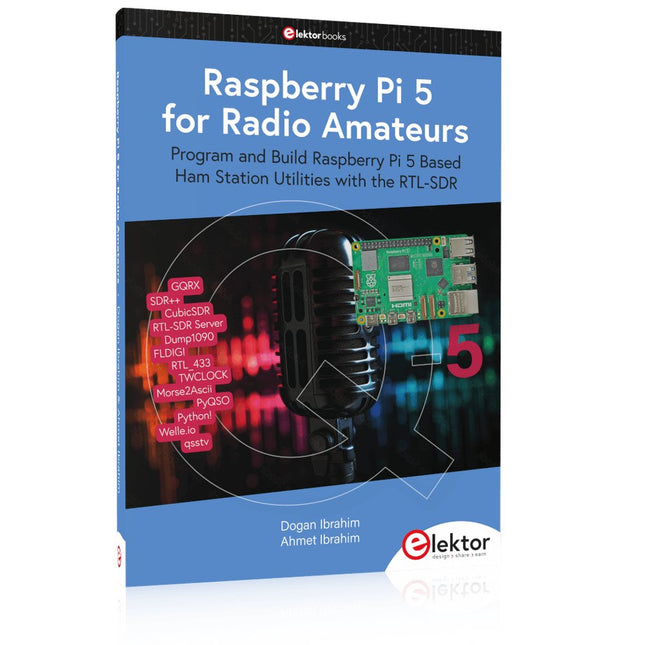
Elektor Publishing Raspberry Pi 5 for Radio Amateurs
Program and Build Raspberry Pi 5 Based Ham Station Utilities with the RTL-SDR The RTL-SDR devices (V3 and V4) have gained popularity among radio amateurs because of their very low cost and rich features. A basic system may consist of a USB based RTL-SDR device (dongle) with a suitable antenna, a Raspberry Pi 5 computer, a USB based external audio input-output adapter, and software installed on the Raspberry Pi 5 computer. With such a modest setup, it is possible to receive signals from around 24 MHz to over 1.7 GHz. This book is aimed at amateur radio enthusiasts and electronic engineering students, as well as at anyone interested in learning to use the Raspberry Pi 5 to build electronic projects. The book is suitable for both beginners through experienced readers. Some knowledge of the Python programming language is required to understand and eventually modify the projects given in the book. A block diagram, a circuit diagram, and a complete Python program listing is given for each project, alongside a comprehensive description. The following popular RTL-SDR programs are discussed in detail, aided by step-by-step installation guides for practical use on a Raspberry Pi 5: SimpleFM GQRX SDR++ CubicSDR RTL-SDR Server Dump1090 FLDIGI Quick RTL_433 aldo xcwcp GPredict TWCLOCK CQRLOG klog Morse2Ascii PyQSO Welle.io Ham Clock CHIRP xastir qsstv flrig XyGrib FreeDV Qtel (EchoLink) XDX (DX-Cluster) WSJT-X The application of the Python programming language on the latest Raspberry Pi 5 platform precludes the use of the programs in the book from working on older versions of Raspberry Pi computers.
€ 39,95
Mitglieder: € 35,96


