Das OWON XDM1241 ist ein schnelles, hochpräzises digitales True RMS Tisch-Multimeter mit einem hochauflösenden 3,5-Zoll-LCD und 50.000 Counts. Seine Gleichspannungsgenauigkeit beträgt bis zu 0,05% und es kann bis zu 65 Werte pro Sekunde messen.
Features
3,5" hochauflösendes LCD (480x320 Pixel)
55.000 Counts
DC-Spannungsgenauigkeit bis zu 0,05%
Bis zu 65 Messwerte pro Sekunde
Zweizeilige Anzeige unterstützt
Trendanalyse im Diagrammmodus zugänglich
AC True RMS-Messungen (Bandbreite: 20 Hz – 1 kHz)
SCPI-Unterstützung: Fernsteuerung des Multimeters über PC-Software über USB-Anschluss
Datenaufzeichnungsfunktion: Sie können die gemessenen Daten im internen Speicher aufzeichnen und die aufgezeichneten Daten dann mit Ihrem Computer lesen und verarbeiten.
Technische Daten
Messbereich
Auflösung
Genauigkeit
Gleichspannung
50.000 mV
0,001 mV
0,1% +10
500,00 mV
0,01 mV
0,05% +5
5,0000 V
0,0001 V
0,05% +5
50.000 V
0,001 V
0,05% +5
500,00 V
0,01 V
0,1% +5
1000,0 V
0,1 V
0,1% +10
Wechselspannung
500 mV ~ 750 V
20 Hz ~ 45 Hz
1% +30
45 Hz ~ 65 Hz
0,5% +30
65 Hz ~ 1 kHz
0,7% +30
Gleichstrom
500 uA
0,01 uA
0,15% +20
5000 uA
0,1 uA
0,15% +10
50 mA
0,001 mA
0,15% +20
500 mA
0,01 mA
0,15% +10
5 A
0,0001 A
0,5% +10
10 A
0,001 A
0,5% +10
Wechselstrom
500 uA ~ 500 mA
20 Hz ~ 1 KHz
0,5% +20
5 A ~ 10 A
1,5% +20
Widerstand
500 Ω
0,01 Ω
0,15% +10
5 KΩ
0,0001 KΩ
0,15% +5
50 KΩ
0,001 KΩ
0,15% +5
500 kΩ
0,01 kΩ
0,15% +5
5 MΩ
0,0001 MΩ
0,3% +5
50 MΩ
0,001 MΩ
1% +10
Häufigkeit
10.000 Hz ~ 60 MHz
/
±(0,2% +10)
Kapazität
50nF ~ 500uF
/
2,5% +10
5mF ~ 50mF
5% +10
Diode
3,0000 V
0,0001 V
/
Kontinuität
1000 Ω
0,1 Ω
Einstellbarer Schwellenwert
Temperatur
Typ K, PT100
Max. Anzeige
55.000 Counts
Datenprotokollierungsfunktion
Protokollierungsdauer
15 ms ~ 9999,999 s
Protokollierungslänge
1.000 Punkte
Anzeige
3,5" TFT LCD (480x320 Pixel)
Stromversorgung
Lithium-Akku über USB-C oder 5 V DC Eingang
Abmessungen
200 x 88 x 150 mm
Gewicht
ca. 0,5 kg
Lieferumfang
1x OWON XDM1241 Multimeter
2x Messleitungen
1x USB-Kabel
1x USB auf DC Kabel
1x Manual
Downloads
Programming Manual
PC Software
Dieses hochempfindliche Picoammeter ist für die Messung und Aufzeichnung sehr kleiner Ströme bis hinunter in den pA-Bereich konzipiert und damit ein ideales Instrument für wissenschaftliche und Forschungsanwendungen, einschließlich Physik, Materialwissenschaft und Elektronenmikroskopie.
Das SPA100 verfügt über alle Funktionen zu einem erschwinglichen Preis und kombiniert Empfindlichkeit, Genauigkeit und Stabilität, so dass der Benutzer niedrige Ströme mit hoher Präzision messen und bequem Biasspannungen für Experimente erzeugen kann. Das SPA100 kann auch als Ultrahochohm-Messgerät eingesetzt werden und misst präzise bis in den Teraohm-Bereich.
Das SPA100 wird über USB an den PC angeschlossen und nutzt die kostenlose Software SPA, die es dem Benutzer ermöglicht, auf einfache Weise zu messen, Grafiken zu erstellen und Messwerte mit Zeitstempeln und Informationen zur Messstabilität zu erfassen.
Technische Daten
Eingang: ±2 mA bis ±200 pA in 8 Bereichen
Genauigkeit und Auflösung (2 Hz):
±2 mA Bereich: ±0,1%, Auflösung <20 nA
±200 uA Bereich: ±0,1%, Auflösung <2 nA
±20 uA Bereich: ±0,2%, Auflösung <200 pA
±2 uA Bereich: ±0,2%, Auflösung <20 pA
±200 nA Bereich: ±0,5%, Auflösung <2 pA
±20 nA Bereich: ±0,5%, Auflösung <200 fA
±2 nA Bereich: ±1,0%, Auflösung <20 fA
±200 pA Bereich: ±1,5%, Auflösung <2 fA
Abtastrate: 2 Hz (18 Bit) oder 10 Hz (16 Bit)
Einstellbarer Filter: 1 Sample bis 64 Samples
Ausgangsspannung: -40 V bis +40 V (in 1 V Schritten), Ausgangswiderstand 2,7 KOhm
Widerstandsmessung: ~1 Kohm bis 40 Tohm (z. B. 40 V Quelle, 1 pA Messung)
Genauigkeit: >±0,5% 1 Mohm bis 1 Tohm
Stromversorgung über USB 2.0 (das Instrument verbraucht im Betrieb bis zu 0,3 A)
Lieferumfang
1x SPA100 Source Picoammeter
1x USB-Kabel
Downloads
Manual
Software
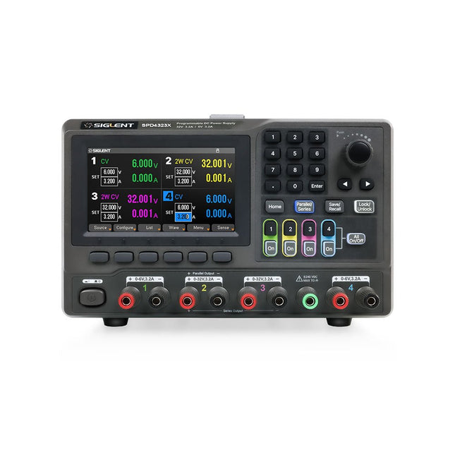
The Siglent SPD4323X is a 4-channel DC Linear Programmable Power Supply equipped with a 4.3-inch TFT-LCD display, friendly human-machine interface, and excellent performance indicators. Real-time waveform display provides engineers with an informative user interface.
SPD4323X offers a total output power of 240 W with a resolution of 1 mV/1 mA. The maximum voltage and current for each channel are as follows:
CH1: 6 V/3.2 A
CH2: 32 V/3.2 A
CH3: 32 V/3.2 A
CH4: 6 V/3.2 A
Features
Rated output power: 240 W
Rated voltage: 32 V, 12 V, 30 V
Up to four high-precision power supplies with independent controllable outputs, supporting CH2 and CH3 series and parallel connections
Clear graphical interface with waveform and timer display modes
5-digit voltage and current display with minimum resolution of 1 mV, 1 mA
Fast output response time: <50us
The high current channel support remote voltage compensation sense function. The maximum compensation voltage is 0.6 V
Overvoltage protection and overcurrent protection or safe and accurate operation
Equipped with a 4.3-inch TFT-LCD display (480 x 272 resolution)
USB and LAN standard communication
USB-GPIB module is optional
Excellent channel density with up to 4 channels in a 3U half rack package
Internal data storage for setups and parameters
Embedded Web Server with instrument communication that doesn’t require software installation
Fully SCPI programming command set support as well as a LabView driver for remote control and system automation
Technische Daten
SPD4323X
SPD4121X
SPD4306X
Channel Output
CH1: Voltage 0 to 6 V Current 0 to 3.2 ACH2: Voltage 0 to 32 V Current 0 to 3.2 ACH3: Voltage 0 to 32 V Current 0 to 3.2 ACH4: Voltage 0 to 6 V Current 0 to 3.2 A
CH1: Voltage 0 to 15 V Current 0 to 1.5 ACH2: Voltage 0 to 12 V Current 0 to 10 ACH3: Voltage 0 to 12 V Current 0 to 10 ACH4: Voltage 0 to 15 V Current 0 to 1.5 A
CH1: Voltage 0 to 15 V Current 0 to 1.5 ACH2: Voltage 0 to 30 V Current 0 to 6 ACH3: Voltage 0 to 30 V Current 0 to 6 ACH4: Voltage 0 to 15 V Current 0 to 1 A
Resolution
1 mV, 1 mA
1 mV, 1 mA
1 mV, 1 mA
Setting Accuracy
Voltage: ±(0.03% of reading+10) mV, Current: ±(0.3% of reading+10) mA
Voltage: ±(0.03% of reading+10) mV, Current: ±(0.3% of reading+10) mA
Voltage: ±(0.03% of reading+10) mV, Current: ±(0.3% of reading+10) mA
Readback Accuracy
Voltage: ±(0.03% of reading+10) mV, Current: ±(0.3% of reading+10) mA
Voltage: ±(0.03% of reading+10) mV, Current: ±(0.3% of reading+10) mA
Voltage: ±(0.03% of reading+10) mV, Current: ±(0.3% of reading+10) mA
Display
4.3" TFT-LCD 5-digit voltage and current display
4.3" TFT-LCD 5-digit voltage and current display
4.3" TFT-LCD 5-digit voltage and current display
Output power
240 W
285 W
400 W
Lieferumfang
1x Siglent SPD4323X Power Supply
1x Power cord (EU)
1x Output test cord (3 A)
1x USB cable
1x Quick start guide
Downloads
Datasheet
Manual
Quick start
Der SDRplay RSPduo ist ein hochleistungsfähiger 14-Bit-SDR-Empfänger mit zwei Tunern. In einem hochwertigen Stahlgehäuse untergebracht, kann jeder Tuner einzeln im Bereich von 1 kHz bis 2 GHz mit bis zu 10 MHz Bandbreite oder beide Tuner können gleichzeitig im Bereich von 1 kHz bis 2 GHz mit bis zu 2 MHz Bandbreite pro Tuner arbeiten.
Dank einer hochstabilen Referenz und externen Taktgebern eignet sich dieses Gerät ideal für industrielle, wissenschaftliche und Bildungsanwendungen.
Features
Dual-Tuner bietet unabhängige Abdeckung von 1 kHz bis 2 GHz unter gleichzeitiger Verwendung von 2 Antennenanschlüssen
14-Bit-ADC-Siliziumtechnologie
Bis zu 10 MHz sichtbare Bandbreite (Single-Tuner-Modus) oder 2 Slices von 2 MHz Spektrum (Dual-Tuner-Modus)
3 per Software auswählbare Antennenanschlüsse (2x 50Ω und 1x 1kΩ hochohmiger symmetrischer/unsymmetrischer Eingang)
Hochohmiger Antennenanschluss (1 kHz bis 30 MHz) mit wählbarem MW-Sperrfilter und 2 Vorselektionsfiltern zur Auswahl
Per Software wählbare AM/FM- und DAB-Rundfunkband-Sperrfilter für die 2 SMA-Antennenanschlüsse (1 kHz bis 2 GHz)
Externer Takteingang und -ausgang ermöglichen die einfache Synchronisierung mit mehreren RSPs oder einem externen Referenztakt
Stromversorgung über das USB-Kabel mit einer einfachen Typ-B-Buchse
11 hochselektive, eingebaute Front-End-Vorwahlfilter an den beiden SMA-Antennenanschlüssen
Per Software wählbarer mehrstufiger rauscharmer Vorverstärker
Bias-T-Netzteil zur Versorgung des an der Antenne montierten LNA
In einem robusten, schwarz lackierten Stahlgehäuse untergebracht
SDRuno – SDR-Software der Extraklasse (für Windows)
Dokumentierte API für die Entwicklung neuer Anwendungen
Technische Daten
Frequenzbereich
1 kHz – 2 GHz
Antennenanschluss
SMA
Antennenimpedanz
50 Ohm
Stromverbrauch (typisch)
Single-Tuner Mode: 180 mA (ohne Bias-T)Dual-Tuner Mode: 280 mA (ohne Bias-T)
USB-Anschluss
USB-B
Maximale Eingangsleistung
+0 dBm kontinuierlich+10 dBm kurzzeitig
ADC Abtastraten
2-10,66 MSPS
ADC Anzahl der Bits
14 bit 2-6,048 MSPS12 bit 6,048-8,064 MSPS10 bit 8,064-9,216 MSPS8 bit >9,216 MSPS
Bias-T
4,7 V100 mA garantiert
Referenz
0,5ppm 24 MHz TCXO.Frequenzfehler auf 0,01ppm im Feld trimmbar.
Betriebstemperatur
−10˚C bis +60˚C
Abmessungen
98 x 94 x 33 mm
Gewicht
315 g
Downloads
Datasheet
Detailed Technical Information
Software
RSPdx-R2 vs RSPduo
RSPdx-R2
RSPduo
Kontinuierlicher Bereich von 1 kHz bis 2 GHz
✓
✓
Bis zu 10 MHz sichtbare Bandbreite
✓
✓
14-Bit-ADC-Siliziumtechnologie plus mehrere Hochleistungs-Eingangsfilter
✓
✓
Per Software wählbare AM/FM- und DAB-Rundfunkband-Sperrfilter
✓
✓
4,7 V Bias-T für die Versorgung eines externen Antennenverstärkers
✓
✓
Stromversorgung über das USB-Kabel mit einer einfachen Typ-B-Buchse
✓
✓
50Ω SMA-Antenneneingang(e) für 1 kHz bis 2 GHz Betrieb (per Software wählbar)
2
2
Zusätzlicher per Software wählbarer Hi-Z-Eingang für bis zu 30 Mhz-Betrieb
✓
Zusätzlicher per Software wählbarer 50-Ω-BNC-Eingang für den Betrieb mit bis zu 200 MHz
✓
Zusätzlicher LF/VLF-Filter für unter 500 kHz
✓
24 MHz Referenztakt-Eingang (+ Ausgang auf RSPduo)
✓
✓
Duale Tuner ermöglichen den Empfang auf 2 völlig unabhängigen 2-MHz-Bereichen
✓
Zwei Tuner ermöglichen Diversity-Empfang mit SDRuno
✓
Robustes schwarz lackiertes Stahlgehäuse
✓
✓
Gesamtleistung unter 2 MHz für MW und LF
++
+
Mehrere gleichzeitige Anwendungen
+
++
Leistung unter schwierigen Fading-Bedingungen (*mit Diversity-Abstimmung)
+
*++
Die digitalen Speicheroszilloskope der SDS2000X Plus-Serie von Siglent sind in Bandbreiten von 100 MHz, 200 MHz und 350 MHz erhältlich, haben eine maximale Abtastrate von 2 GSa/s, eine maximale Aufzeichnungslänge von 200 Mpts/Kanal und bis zu 4 analoge Kanäle + 16 digitale Kanäle, Mixed-Signal-Analysefähigkeit.
Die SDS2000X Plus-Serie nutzt die SPO-Technologie von Siglent mit einer maximalen Wellenformerfassungsrate von bis zu 120.000 wfm/s (Normalmodus, bis zu 500.000 wfm/s im Sequenzmodus), einer Anzeigefunktion mit 256 Intensitätsstufen sowie einer Farbtemperatur Anzeigemodus. Es verwendet außerdem ein innovatives digitales Triggersystem mit hoher Empfindlichkeit und geringem Jitter. Das Triggersystem unterstützt mehrere leistungsstarke Triggermodi, einschließlich serieller Bus-Triggerung. Verlaufsaufzeichnung von Wellenformen, Sequenzerfassung sowie Such- und Navigationsfunktionen ermöglichen die Erfassung, Speicherung und Analyse erweiterter Wellenformaufzeichnungen. Eine beeindruckende Auswahl an Mess- und Mathematikfunktionen, Optionen für einen 50-MHz-Wellenformgenerator sowie serielle Dekodierung, Maskentest, Bode-Plot und Leistungsanalyse sind weitere Merkmale des SDS2000X Plus. Ein 10-Bit-Erfassungsmodus hilft dabei, Anwendungen zu erfüllen, die eine Auflösung von mehr als 8 Bit erfordern.
Der große kapazitive 10,1"-Touchscreen unterstützt Multi-Touch-Gesten, während die Remote-Websteuerung sowie die Unterstützung für Maus und externe Tastatur die Bedieneffizienz des SDS2000X Plus erheblich verbessern.
Features
Erhältlich mit 100 MHz, 200 MHz, 350 MHz Bandbreite (aufrüstbar auf 500 MHz)
Echtzeit-Abtastrate bis zu 2 GSa/s
Aufzeichnungslänge bis zu 200 Mpts
Serieller Bus-Trigger und Decoder, unterstützt I²C, SPI, UART, CAN, LIN, CAN FD, FlexRay, I²S und MIL-STD-1553B
Bietet 10-Bit-Modus, vertikalen und horizontalen Zoom
Der kapazitive Touchscreen unterstützt Multi-Touch-Gesten
Siglent SDS2000X Plus Oszilloskope
SDS2102X Plus
SDS2104X Plus
SDS2204X Plus
SDS2354X Plus
Bandbreite
100 MHz
100 MHz
200 MHz
350 MHz
Kanäle
2
4
4
4
Echtzeit-Abtastrate
2 GSa/s
2 GSa/s
2 GSa/s
2 GSa/s
Erfassungsrate
120,000 wfm/s
120,000 wfm/s
120,000 wfm/s
120,000 wfm/s
Speichertiefe
200 Mpts/ch
200 Mpts/ch
200 Mpts/ch
200 Mpts/ch
Lieferumfang
Siglent SDS2102X Plus Oszilloskop
Passive Sonden
Netzkabel
USB-Kabel
Manual
Downloads
Datasheet
Manual
Quick guide
User manual
Firmware
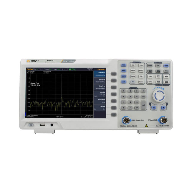
Der OWON XSA815-TG 9 kHz-1,5 GHz ist ein kostengünstiger Spektrumanalysator mit Tracking-Generator und einer Frequenzauflösung von 1 Hz.FeaturesFrequenzbereich von 9 kHz bis 1,500009 GHz9-Zoll-Display9 kHz bis 1 MHz -95 dBm Angezeigter durchschnittlicher Geräuschpegel, 1 MHz bis 500 MHz 140 dBm (typisch), Phasenrauschen-10 kHz 100 kHz 1 MHz Auflösungsbandbreite (-3 dB): 1 Hz bis 1 MHz, in der Reihenfolge 1-3-5-10Tracking-Generator-Kit: 100 kHz bis 1,500009 GHzTechnische DatenFrequenzbereich9 kHz bis 500.009 MHzFrequenzauslösung1 HzFrequenzspanne9 kHz bis 1.500009 GHzSpan Range0 Hz, 100 Hz to max frequency of instrumentSpan Uncertainty± span / (sweep points-1)SSB Phase Noise (20°C to 30°C, fc=1 GHz) Carrier Offset10 kHz Resolution Bandwidth (-3 dB)1 Hz to 1 MHz, in 1-3-5-10 sequenceRBW AccuracyResolution Filter Shape Factor (60 dB: 3 dB)Video Bandwidth (-3 dB)10 Hz to 1 MHz, in 1-3-5-10 sequenceAmplitude measurement rangeDANL to +10 dBm, 100 kHz to 10 MHz, Preamp Off DANL to +20 dBm, 10 MHz to 1.5 GHz, Preamp OffReference Level-80 dBm to +30 dBm, 0.01dB by stepPreamp20 dB, nominal, 100 kHz to 1.5 GHzInput Attenuator0 to 40 dB, 1 dB by step Display Average Noise Level Input attenuation = 0 dB, RBW = VBW = 100 Hz, sample detector, trace average ≥ 50, 20°C to 30°C, input impedance = 50 Ω)Preamp Off 9 kHz to 1 MHz-95 dBm (Typical), Preamp Off 1 MHz to 500 MHz-140 dBm (Typical), Preamp On 100 kHz to 1 MHz-135 dBm (Typical), Preamp On 1 MHz to 500 MHz-160 dBm (Typical),Tracking Generator (optional) Frequency Range100 kHz to 1.500009 GHzOutput power level range-40 dBm to 0 dBmOutput level resolution 1 dB Output flatnessRelative to 50 MHz | ±3 dBTracking generator spuriousHarmonic spurious -30 dBc (Tracking generator output power -10 dBm) Non-harmonic spurious -40 dBc (Tracking generator output power -10 dBm)Tracking generator to input terminal isolation-60 dB (Tracking generator output power 0 dBm)Tracking generator to input terminal isolation-60 dB (Tracking generator output power 0 dBm)Tracking generator to input terminal isolation-60 dB (Tracking generator output power 0 dBm)Abmessungen375 x 185 x 120 mmGewicht3,7 kgLieferumfang1x XSA815-TG1x 220 V AC-Netzkabel1x USB-Kabel1x SchnellstartanleitungDownloadsQuick GuideSpecifications
Cool Projects for Test, Measurement, and Control
The Raspberry Pi has dominated the maker scene for many years. Freely accessible I/O pins have made it one of the most popular processor boards of all time. However, the classic Raspberry Pi has no analog inputs. Direct measurement of analog values is therefore not possible. Consequently, photodiodes, NTCs, Hall sensors, etc. cannot be read directly. In addition, the pins are connected directly to the exposed contacts, i.e. without a driver or protection circuit. This can quickly destroy the central controller and thus the entire Raspberry Pi.
These problems can be elegantly solved with the Pico. As a front-end, it can easily handle a wide range of measurement tasks. In addition, the Pico is much cheaper than a classic Raspberry Pi 4 or 5. If a faulty circuit leads to the destruction of the Pico, this is relatively easy to handle. This makes the combination of a classic Raspberry Pi 4 or 5 and the Pico an ideal pair.
The book introduces the broad and highly topical field of modern controller technology using the combined force of a Raspberry Pi 4 or 5 and a Raspberry Pi Pico. In addition to a detailed introduction to the operation and functionality of the controller boards themselves, the book also focuses on data acquisition and processing with digital processors. Especially the combination of both systems offers a wide range of interesting possibilities.
Some practical projects from the contents:
USB between Raspberry Pi 4 or 5 and Pico
I²C Communication and Pico as an I²C device
Voltmeter and Computer Thermometer
Pico W as a Web Server and WLAN Scanner
Frequency Meters and Generators
OLED Displays on Raspberry Pi 4 or 5 and Pico
Energy Saving Monitor
Which Astronauts are in Orbit?
Mini Monitor for Current Bitcoin Exchange Rate
Das OWON SPE6103 ist ein 1-Kanal Labornetzteil (300 W) in einem kleinen Gehäuse mit Funktionen wie Überspannungs- und Überstromschutz. Es verfügt über eine hohe Auflösung von 10 mV/1 mA. Das 2,8-Zoll-LCD zeigt die folgenden Informationen an (Konstantspannungsausgang, Konstantstromausgang, kumulierte Laufzeit, tatsächliche Ausgangsleistung, Kanalausgangsstatus, tatsächlicher Spannungsausgang, tatsächlicher Stromausgang). Features Kleines Gehäuse zum einfachen Tragen Hohe Auflösung: 10 mV/1 mA Wellenformbearbeitungsausgabe auflisten, 10 Gruppen von Timing-Ausgabefunktionen bearbeitbar Geringe Welligkeit/Geräusch Überspannungs-/Überstromschutz Überwachungsfunktion für Ausgangsspannung und Stromkurve Intelligente Temperaturregelung der Lüfterkühlung 2,8-Zoll-TFT-LCD-Display USB-Kommunikationsschnittstelle, unterstützt SCPI Technische Daten Modell SPE6102 SPE6103 Nennleistung (0-40°C) Spannung 0-60 V 0-60 V Strom 10 A 10 A Ausgangsleistung 200 W 300 W USB-Ausgang 5 V/1 A (SPE-Serie) oder Unterstützung der Schnellladeprotokolle QC2.0, QC3.0, BC1.2, Apple, Huawei, Samsung (optional) Lastregulierung Spannung ≤30 mV Strom ≤20 mA Leistungsregulierung Spannung ≤30 mV Strom ≤20 mA Einstellung der Auflösung Spannung 10 mV Strom 1 mA Auflösung der Rücklesung Spannung 10 mV Strom 1 mA Wertauflösung (innerhalb von 12 Monaten) (25 ±5°C) Spannung ≤0.1% ±30 mV ≤0.1% ±30 mV Strom ≤0.05% ±10 mA Rücklesung Wertauflösung (25 ±5°C) Spannung ≤0.1% ±30 mV ≤0.1% ±30 mV Strom Welligkeit/Rauschen Spannung (Vp-p) ≤50mVp-p ≤50mVp-p Spannung (rms) ≤5mVrms ≤5mVrms Strom (rms) ≤30mAp-p Ausgangstemperaturkoeffizient (0-40°C) Spannung 100ppm/°C Strom 200ppm/°C Rücklese-Temperaturkoeffizient Spannung 100ppm/°C Strom 200ppm/°C Reaktionszeit (50-100% Nennlast) ≤1,0ms Speicher 4 Gruppen von Daten Betriebstemperatur 0-40°C Included 1x OWON SPE6103 1x Netzkabel 1x Kurzanleitung 1x USB-Kabel 1x Sicherung Downloads User Manual Programming Manual Software
Learn to interface and program hardware devices in a wide range of useful applications, using ARM7 microcontrollers and the C programming language. Examples covered in full detail include a simple LED to a multi-megabyte SD card running the FAT file system.
Features of this book
Build prototype circuits on breadboard or Veroboard and interface to ARM microcontrollers.
A 32-bit ARM7 microcontroller is used in interfacing and software examples.
Interfacing principles apply to other ARM microcontrollers and other non-ARM microcontrollers as well.
Example programs are written in the C programming language.
Use only free or open source software.
Download and install all programming tools from the Internet.
Template project files are provided for easy project creation.
Hardware
Interface to LEDs, transistors, optocouplers, relays, solenoids, switches, keypads, LCD displays, seven segment displays, DC motors, stepper motors, external analogue signals using the ADC, RS232, RS-485, TWI, USB, SPI and SD memory cards.
Software
Once hardware has been interfaced to a microcontroller, software must be written to control the hardware. You will learn how to write programs to operate externally interfaced hardware devices, use timers and interrupts. Also learn how to port FAT file system code for use with an SD memory card, program the PWM to produce an audio sine wave, program the PWM to speed control a DC motor and more.
A chapter on more advanced ARM microcontrollers is included with an overview of some of the newest ARM microcontrollers and their features.
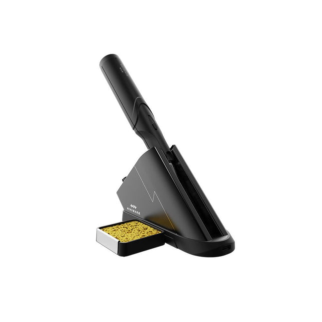
Die Miniware Cordless Soldering Station TS1C (mit integriertem OLED-Bildschirm und Bluetooth) ist ein intelligentes Lötwerkzeug, das in weniger als 20 Sekunden auf bis zu 400°C erhitzt. Dank des eingebauten Akkus liegt der kabellose Lötstift gut in der Hand und lässt sich bequem bedienen.
Features
Neue hocheffiziente Superkondensator-Energiespeichertechnologie, 10.000 Lade- und Entladezeiten
Separates Design + echtes Wireless, genießen Sie kabelloses Löterlebnis
BLE4.2 Bluetooth-Kommunikationstechnologie zur Fernsteuerung und -einstellung
Standard PD2 20 V, 45 W maximale Leistungsaufnahme, bis zu 36 W Lötleistung, kann kontinuierlich mehr als 180 Lötstellen (0805) mit einer einzigen vollen Ladung löten
Vorheizen der Steuerstation zur Verbesserung der Heizeffizienz
3 Erweiterungssteckplätze für Zubehör
Kontrollstation
Standard PD2 20 V 45 W maximale Leistungsaufnahme, Überstrom-Sicherheitsschutz
OLED-Bildschirm mit 128 x 64 Pixeln, Anzeige des Lötstiftstatus in Echtzeit
Vorheizen der Steuerstation, Verbesserung der Heizeffizienz
Fernbedienung und -einstellung: Temperaturregulierung, Menüeinstellung, Anzeige von Geräteinformationen und -status usw.
Funktioniert als Lötständer und Ladestation
3 Erweiterungssteckplätze für mehrere erweiterbare Zubehörteile wie Schwammsteckplatz
Lötstift
Eingebauter 750F hocheffizienter Energiespeicher-Superkondensator, kann über die Kontrollstation (oder in Notfällen über die USB-Typ-C-Schnittstelle) aufgeladen werden
36 W maximale Heizleistung, kann mehr als 180 Lötstellen (0805) kontinuierlich mit einer einzigen vollen Ladung löten
Kompatibel mit Miniware 3,5 mm Audio-Interface-Lötspitzen (Lötspitzenserie TS80/80P)
Boost-Modus (Halten der Taste am Stift)
Lieferumfang
TS1C Lötstift
TS1C-Kontrollstation
Lötspitze (TS-B02)
Silikonkabel
Schwammhalter inkl. Schwamm
Manual
Elektor GREEN and GOLD members can download their digital edition here.
Not a member yet? Click here.
USB Measurement AdapterTesting Current and Signal Quality of USB Ports
4...20 mA Current Output for Arduino UnoA Reliable, EMI-Insensitive Current Loop Interface
Vacuum Cleaner Automatic ControlKeep Your Tools’ Work Area Clean
DDS Generator with ATtiny
Opamp-Tester V2New PCB – Now Also Suitable for SMDs
550-mW “Lamp” Audio AmplifierGet the Warm Sound of Vacuum Tubes With Ease
Fuse GuardMonitoring a Fuse with a Flashing LED
HQ RIAA PreamplifierGet the Most Out of Your Vinyl Records!
Turntable Speed CalibratorAn Arduino-Based 100–120 Hz Strobe Light Generator
Elektor Classics: video buffer/repeater
Infrared Remote-Controlled DimmerControl Your Halogen or LED Floor Lamp Effortlessly and With Style
How to Use switch…case on Strings in C++/Arduino IDE
Magnet FinderWith a Simple Hall-Effect Sensor
Raspberry Pi Smart Power ButtonA Solution for Raspberry Pi Up to Model 4
Essential Maker TipsProfessional Insights for Everyday Making
Practical Projects with the 555 TimerDC Motor Control and Fast Reaction Challenges
Basic AC-Load-On MonitorSave Energy with a Simple Device
Power Banks in ParallelA Three-Day Continuous Power Solution
VFO Up to 15 MHzAn Implementation With Raspberry Pi Pico
Violin Tuner with ATtiny202
Elektor Classics: video amplifier for B/W television sets
Capacitance Meter20 pF to 600 nF
Quasi-Analog Clockwork Mk IITwo LED Rings for Hours and Minutes
You Can Do Anything You Want(with the Arduino Ecosystem at Your Side)
Neon Lamp Dice
Elektor Classics: RTTY calibrator indicator
Inspiring Hardware Designs for Your ESPs
Elektor Classics: variable 3 A power supply
RGB LEDs with Integrated Control CircuitLight with Precision: ICLEDs Set Standards
Experiment: Towards a Mixed-Signal Theremin?Blending Modern Time-of-Flight Sensors With the Timeless XR2206 Analog Generator
ESP32 Audio Transceiver Board (Part 1)SD Card WAV File Player Demo
Infographics: Circuits and Circuit Design 2025
Small Audio MixerA Simple and Versatile Scalable Design
Smart Staircase Light TimerSave More Money on the Energy Bill!
Smarten Up Your ShuttersControlling Velux Hardware With an ESP32 and MQTT
Solid-State Foot WarmerEnergy-Efficient Comfort
Is the M5Stamp Fly Quadcopter the Next Tello?
Boosting Wi-Fi Range of the ESP32-C3 SuperMiniA Simple and Effective Antenna Mod
ZD-8968 Hot-Air Soldering StationA Budget-Friendly Workhorse or Just Hot Air?
Parking Sensor TesterFinding Defects in the PDC System of a Car