
Suchergebnisse für "esp OR 32s OR pinboard OR breakout OR modules"
-
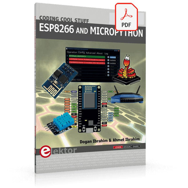
Elektor Digital ESP8266 and MicroPython (E-book)
Recently, the development of a tiny chip called the ESP8266 has made it possible to interface any type of microcontroller to a Wi-Fi AP. The ESP8266 is a low-cost tiny Wi-Fi chip having fully built-in TCP/IP stack and a 32-bit microcontroller unit. This chip, produced by Shanghai based Chinese manufacturer Espressif System, is IEEE 802.11 b/g/n Wi-Fi compatible with on-chip program and data memory, and general purpose input-output ports. Several manufacturers have incorporated the ESP8266 chip in their hardware products (e.g. ESP-xx, NodeMCU etc) and offer these products as a means of connecting a microcontroller system such as the Android, PIC microcontroller or others to a Wi-Fi. The ESP8266 is a low-power chip and costs only a few Dollars. ESP8266 and MicroPython – Coding Cool Stuff is an introduction to the ESP8266 chip and describes the features of this chip and shows how various firmware and programming languages such as the MicroPython can be uploaded to the chip. The main aim of the book is to teach the readers how to use the MicroPython programming language on ESP8266 based hardware, especially on the NodeMCU. Several interesting and useful projects are given in the e-book (pdf) to show how to use the MicroPython in NodeMCU type ESP8266 hardware: Project “What shall I wear today?”: You will be developing a weather information system using a NodeMCU development board together with a Text-to-Speech processor module. Project “The Temperature and Humidity on the Cloud”: You will be developing a system that will get the ambient temperature and humidity using a sensor and then store this data on the cloud so that it can be accessed from anywhere. Project “Remote Web Based Control”: You will be developing a system that will remotely control two LEDs connected to a NodeMCU development board using an HTTP Web Server application.
€ 29,95
Mitglieder: € 26,96
-
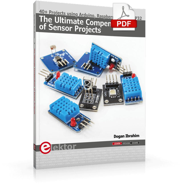
Elektor Digital The Ultimate Compendium of Sensor Projects (E-book)
40+ Projects using Arduino, Raspberry Pi and ESP32 This book is about developing projects using the sensor-modules with Arduino Uno, Raspberry Pi and ESP32 microcontroller development systems. More than 40 different sensors types are used in various projects in the book. The book explains in simple terms and with tested and fully working example projects, how to use the sensors in your project. The projects provided in the book include the following: Changing LED brightness RGB LEDs Creating rainbow colours Magic wand Silent door alarm Dark sensor with relay Secret key Magic light cup Decoding commercial IR handsets Controlling TV channels with IT sensors Target shooting detector Shock time duration measurement Ultrasonic reverse parking Toggle lights by clapping hands Playing melody Measuring magnetic field strength Joystick musical instrument Line tracking Displaying temperature Temperature ON/OFF control Mobile phone-based Wi-Fi projects Mobile phone-based Bluetooth projects Sending data to the Cloud The projects have been organized with increasing levels of difficulty. Readers are encouraged to tackle the projects in the order given. A specially prepared sensor kit is available from Elektor. With the help of this hardware, it should be easy and fun to build the projects in this book.
€ 34,95
Mitglieder: € 31,46
-

Elektor Digital Elektor January/February 2026 (PDF) EN
Elektor GREEN and GOLD members can download their digital edition here. Not a member yet? Click here. Low-Noise Lab Power Supply (1)A Quiet Source for Sensitive Circuits STM32 Edge AI Contest 2025: The Winners Batteries TodayTechnology and Differences in Lithium Batteries Adjustable Electronic LoadStatic + Dynamic DC Load Step-Down Converter from 48 V to 5 VThe Story of Circuit Development Autonomous Sensor Node v2.0Part 2: Hardware Validation and Power Optimizations VaristorsPeculiar Parts, the Series Graphical Grid Frequency MeterMonitor Grid Quality Starting Out in Electronics……Brings Its Own End Peak Current Load SMD FerritesMore Resilient Against Current Peaks Elektor Live! Expert Day 2025 Energy Harvesting Set to Accelerate IoT and IIoT Use CasesHow Energy Harvesting Frees IoT from the Grid Fnirsi DPS-150Compact and Portable Power Supply and Converter Adjustable USB-C Power SourceTurn Your USB-C Charger Into an Adjustable Power Supply Simple Charger and Capacity TesterWith Two Cheap “Off-the-Shelf” Modules Smart Color Detector with AI Voice and Playback PbMonitor v2.0Introduction to the Updated Battery Monitoring System A Fan for the Mini Reflow PlateSmart Modifications That Improve Results From Life’s ExperienceThe Tsunami of Indulgence Err-lectronicsCorrections, Updates, and Readers’ Letters 2026: An AI OdysseyWhen Models Start Dictating the Hardware Precision Picoammeter (2)Assembling, Calibration, and Test Wireless Device Poweringwith Inductive Technology AI-Based Autonomous DrivingThe RDW’s Self Driving Challenge 2024 Sound Card as Signal GeneratorPC as DCF77 Test Transmitter
€ 9,50
-
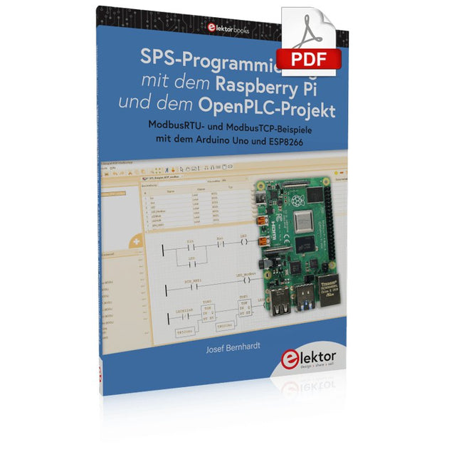
Elektor Digital SPS-Programmierung mit dem Raspberry Pi und dem OpenPLC-Projekt (PDF)
Einführung in die SPS-Programmierung mit dem Open-Source-Projekt auf dem Raspberry Pi und Modbus-Beispiele mit dem Arduino Uno und ESP8266 Die SPS-Programmierung ist heute in der Industrie und in der Hausautomation sehr weit verbreitet. In diesem Buch beschreibt der Autor, wie der Raspberry Pi 4 als SPS eingesetzt werden kann. Angefangen mit der Softwareinstallation auf dem Raspberry Pi und dem SPS-Editor auf dem PC geht es nach einer Beschreibung der Hardware an das Programmieren. Es folgen interessante Beispiele nach IEC 61131-3 in den verschiedenen Programmiersprachen. Ausführlich wird auch erklärt, wie der SPS-Editor benutzt wird und wie die Programme auf den Raspberry Pi geladen und ausgeführt werden. Angefangen mit der Programmierung mit KOP (Kontaktplan) über ST (Structured Control Language) bis zu AS (Special Function Chart) werden alle IEC-Sprachen mit Beispielen behandelt. Diese können auf der Website des Autors heruntergeladen werden. Auch die Vernetzung kommt nicht zu kurz. Der Arduino Uno und der ESP8266 werden als ModbusRTU- bzw. ModbusTCP-Module programmiert, um Zugriff auf externe Peripherie zu erhalten. Damit ist es möglich, Sensoren einzulesen und Verbraucher zu schalten. Interessant dürften auch E/A-Schaltungen sein, die dem 24V-Industriestandard entsprechen. Befehlsübersichten für ST und KOP runden das Buch ab. Nach dem Durcharbeiten des Buches ist der Leser in der Lage, eigene SPS-Steuerungen mit dem Raspberry Pi zu verwirklichen.
€ 32,80
Mitglieder: € 29,52
-
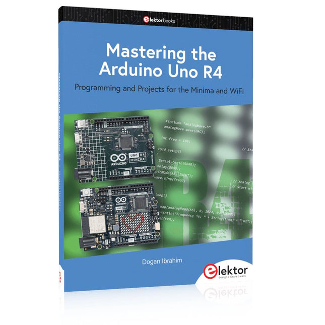
Elektor Publishing Mastering the Arduino Uno R4
Programming and Projects for the Minima and WiFi Based on the low-cost 8-bit ATmega328P processor, the Arduino Uno R3 board is likely to score as the most popular Arduino family member, and this workhorse has been with us for many years. Eleven years later, the long-overdue successor, the Arduino Uno R4, was released. It is built around a 48 MHz, 32-bit Arm Cortex-M4 microcontroller and provides significantly expanded SRAM and Flash memory. Additionally, a higher-precision ADC and a new DAC are added to the design. The Uno R4 board also supports the CAN Bus with an interface. Two versions of the board are available: Uno R4 Minima, and Uno R4 WiFi. This book is about using these new boards to develop many different and interesting projects with just a handful of parts and external modules. All projects described in the book have been fully tested on the Uno R4 Minima or the Uno R4 WiFi board, as appropriate. The project topics include the reading, control, and driving of many components and modules in the kit as well as on the relevant Uno R4 board, including LEDs 7-segment displays (using timer interrupts) LCDs Sensors RFID Reader 4x4 Keypad Real-time clock (RTC) Joystick 8×8 LED matrix Motors DAC (Digital-to-analog converter) LED matrix WiFi connectivity Serial UART CAN bus Infrared controller and receiver Simulators … all in creative and educational ways with the project operation and associated software explained in great detail.
€ 44,95
Mitglieder: € 40,46
-

Elektor Digital Elektor Januari/Februari 2026 (PDF) NL
Elektor GREEN en GOLD leden kunnen deze uitgave hier downloaden. Nog geen lid? Klik hier om een lidmaatschap af te sluiten. Low-noise laboratorium voeding (1)Een stabiele voedingsbron voor gevoelige circuits STM32 Edge-AI Contest 2025: De winnaars Batterijen van vandaagTechnologie en verschillen in lithiumbatterijen Instelbare elektronische belastingStatische en dynamische DC-belasting Step-down converter van 48 V naar 5 VHet verhaal achter de ontwikkeling van een schakeling Autonome sensornode v2.0Deel 2: Hardware-validatie en vermogensoptimalisatie VaristorenVreemde onderdelen Grafische netfrequentiemeterControleer de kwaliteit van het stroomnet Alle begin......maakt er een eind aan Piekstroombelasting SMD-ferrietenBeter bestand tegen stroompieken Elektor Live! Expert Day 2025 Energy harvesting belooft de implementatie van IoT- en IIoT-toepassingen te zullen versnellenHoe energy harvesting IoT loskoppelt van het stroomnet Fnirsi DPS-150Compacte draagbare voeding en converter Instelbare USB-C voedingsbronMaak van uw USB-C-lader een regelbare voeding Eenvoudige lader en capaciteitstesterMet twee goedkope kant-en-klaar modules Slimme kleurendetector met AI-stem en afspeelfunctie PbMonitor v2.0Overzicht van het vernieuwde accu-bewakingssysteem Een ventilator voor de mini-reflow plateSlimme aanpassingen die de resultaten verbeteren Uit het leven gegrepende tsunami der verwendheid Err-lectronicsCorrecties, updates en lezersbrieven 2026: Een AI-odysseeWanneer modellen de hardware bepalen Precisie pico-ampèremeter (2)Montage, kalibratie en test Draadloze energievoorziening van apparatenMet inductieve technologie Autonoom rijden op basis van AIDe Self Driving Challenge 2024 van de RDW Geluidskaart als signaalgeneratorPC als DCF77-testzender
€ 9,95
-

Peak Peak Atlas Pro Pack (LCR45 und DCA75)
Dieses Paket enthält den LCR45, perfekt für erfahrene Bastler und Experten. Es beinhaltet außerdem das sehr populäre DCA Pro (model DCA75), fantastisch für die Identifikation von Komponenten. Kompletiert wird das Paket durch ein USB-Kabel und einem USB-Stick mit der nötigen Software. DCA75 Der DCA75 unterstützt alle Komponenten die von PEAK Atlas DCA55 unterstützt werden und beinhaltet sogar noch weitere: Transistoren (BJT’s mit Darlingtons und “digitale” Transistoren), Silikon und Germanuim Typen. Misst den Verstärkungsfaktor, VBE, Ableitstrom und die Sättigungsspannung. Unijunctiontransistoren (UJT’s) werden nicht unterstützt. MOSFET‘s, Anreicherungstyp und Abreicherungstyp. Misst mit einem Ansprechwert (von ID=5 mA), einer geschätzten Transkonduktanz (in einer Spanne von 3 mA - 5 mA) und RDS(on) mit einer Auflösung von 1 Ω. JFETs, mit SiC-Typen. Misst mit pinch-off Spannung (ID=5μA), geschätzter Transkonduktanz (in einer Spanne von 3 mA – 5 mA) und RDS(on) bei einer Auflösung von 1 Ω. IGBTs (Biopolartransistor). Misst mit einem Ansprechwert (IC=5mA), geschätzter Transkonduktanz (in einer Spanne von 3 mA – 5 mA) und Sättigungsspannung. Dioden und Diodennetzwerke. Misst eine Durchlassspannung bei 5 mA. LED’s und zweifarbige LED’s (2 Leiter und 3 Leiter Typ). Misst Durchlassspannung von jedem LED-Element bei 5 mA. Zener Dioden mit einer gemessenen Zener Spannung bis zu 9 V bei 5 mA. Spannungsregulatoren (misst Spannungsregulierung von < 8 V, Abfallspannung, Ruhestrom). Triac’s und Thyristoren welche weniger als 10 mA von Steuerstrom und Haltestrom benötigen. Unabhängig oder mit PC funktionstüchtig Das ATLAS DCA75 PRO kann eigenständig arbeiten oder mit einem PC verbunden werden. Wie auch immer, das DCA Pro wird automatisch die Komponente und die Kontaktbelegung identifizieren. Außerdem misst es eine Reihe von Komponenteneigenschaften, wie den Transistorfaktor, Ableitungen, MOSFET und IGBT-Spannung. Curve Tracing Wenn das ATLAS DCA75 PRO mit einem PC mit dem beiliegenden USB-Kabel verbunden wird, hat man einen Überblick über eine Reihe von Schwachspannungskurven. Verschiedene Graphen sind nutzbar, weitere folgen: Bipolartransistor Ausgabekennlinie, IC vs VCE Bipolartransistor Verstärkungsfaktoren, hFE vs VCE Bipolartransistor Verstärkungsfaktoren, hFE vs IC MOSFET und IGBT Ausgabefunktion, ID vs VDS MOSFET und IGBT Transferfunktion, ID vs VGS JFET Ausgabefunktion, ID vs VDS JFET Transferfunktion, ID vs VGS Spannungsregulator, VOUT vs VIN Spannungsregulator, IQ vs VIN PN Anschluss I/V Kurven, vorwärts und rückwärts Optionen (für Zener Dioden). Beim Curve tracing werden Testparameter von +/- 12 V, +/- 12 mA eingestellt. Sämtliche curve-tracing Daten können direct in Excel© für weitere Grafikanalysen eingespeist werden. Die Software ist für die Betriebssysteme Windows XP, Vista, 7, 8 and 10 gemacht. LCR45 Ein großartiger LCR Analysator, welcher die passiven Komponenten (Spulen, Kondensatoren und Widerstände) messen kann.Das LCR45 bietet eine erhöhte Messauflösung (besser aks 0.1 uH!). Des Weiteren kann die Test-Frequenz DC manuel oder automatisch auf, 1 kHz, 15 kHz und 200 kHz verändert werden. Nicht hergestellt für schaltungsinterne Messungen. Automatische oder manuelle Komponenten Slektion: Spule, Kondensator oder Widerstand Automatische oder manuelle Test-Frequenz- Selektion: DC, 1 kHz, 15 kHz und 200 kHz Induktivitäten von 0.1 uH bis 10 H Kapazitäten von 0.1 pF bis 10,000 uF Widerstände von 0.1 Ohm bis 2 MOhm Induktivitäten Messung zeigt auch die Spulenwiderstände Zeigt "Component type and values", "Complex Impedance", "Magnitude/Phase" und "Admittance" Test-Frequenz wird für alle Messungen angezeigt Abweichung von 1,5% für Spulen und Kondensatoren (siehe Tabelle für weiterer Details) Abweichung von 1% für Widerständen Tastkopf wird mit 2 mm vergoldeten Steckern und Buchsen komplettiert Vergoldete Prüfspitzen sind austauschbar Lieferumfang LCR45 DCA75 Extra GP23 Batterie Extra AAA Zelle Dual Carry Gehäuse
€ 320,11
-

Elektor Digital Elektor September/Oktober 2023 PDF (NL)
Elektor GREEN- und GOLD-Mitglieder können diese Ausgabe hier herunterladen. Noch kein Mitglied? Klicken Sie hier , um eine Mitgliedschaft abzuschließen. Raspberry Pi Pico als Spektrumanalysator FFTs mit billiger Hardware ±40 V linearer Spannungsregler alternatives Netzteil für die Fortissimo-100 Endstufe... und andere! Flexible drahtlose Kommunikation mit einer MCU EEPROM eröffnet Vernetzungsmöglichkeiten für drahtlose MCUs 5.000 € zu gewinnen! Nehmen Sie am STM32 Wireless Innovation Design Contest teil 2023: eine KI-Odyssee Beginnen Sie mit Code Interpreter von ChatGPT LoRa – ein Schweizer Taschenmesser Teil 1: Das LoRa-Protokoll und seine Vorteile Einstellbare Stromsenke mit integriertem Taktgenerator Testen Sie Netzteile, Spannungswandler und Batterien Zwei neue Arduino UNO R4-Boards: Minima und WiFi Logarithmische Potentiometer sie sind exponentiell! Motortreiber-Breakout-Board ein BoB für einen 5 A DC-Motortreiber von 3×3 mm Elektronik aus Life Periculosa Bietet Mobilfunk den niedrigsten Stromverbrauch für IoT? Energiebedarf von LTE-M und NB-IoT in LPWAN-Bereitstellungen Drahtlose Kommunikation in IoT-Systemen mit Arduino MKR-Modulen das richtige Board für WiFi, LoRa und andere Standards Wechselstromverluste in magnetischen Bauteilen Vermeiden Sie heiße Spulen! Maßnahmen für optimale Cloud-Konnektivität Matter-Implementierung: Was ist für die Bereitstellung von Matter-Geräten erforderlich? YARD Stick Eins Sub-1-GHz-Wireless-Testgerät Halterelais Fremde PIC vor zehn – pünktlich Entwurf eines SDR-Zeitsignalempfängers Sorgfaltspflichtrichtlinie „Business as Usual“ wird nicht funktionieren Aller Anfang... ...verstärkt Spannungen Infraschallrekorder mit dem Arduino Pro Mini ein Beispielprojekt aus der Elektor-Publikation „Arduino & Co“ Cloudbasierter Energiezähler mit einem ESP32-Modul und einem PZEM-004T Spannungs-/Stromsensor Ein Leitfaden zur puristischen Programmierung (Teil 2) genaues Timing, UART und Debugging
€ 9,95
-

Elektor Digital Raspberry Pi Pico Essentials (E-book)
Program, build, and master over 50 projects with MicroPython and the RP2040 microprocessor The Raspberry Pi Pico is a high-performance microcontroller module designed especially for physical computing. Microcontrollers differ from single-board computers, like the Raspberry Pi 4, in not having an operating system. The Raspberry Pi Pico can be programmed to run a single task very efficiently within real-time control and monitoring applications requiring speed. The ‘Pico’ as we call it, is based on the fast, efficient, and low-cost dual-core ARM Cortex-M0+ RP2040 microcontroller chip running at up to 133 MHz and sporting 264 KB of SRAM, and 2 MB of Flash memory. Besides its large memory, the Pico has even more attractive features including a vast number of GPIO pins, and popular interface modules like ADC, SPI, I²C, UART, and PWM. To cap it all, the chip offers fast and accurate timing modules, a hardware debug interface, and an internal temperature sensor. The Raspberry Pi Pico is easily programmed using popular high-level languages such as MicroPython and or C/C++. This book is an introduction to using the Raspberry Pi Pico microcontroller in conjunction with the MicroPython programming language. The Thonny development environment (IDE) is used in all the projects described. There are over 50 working and tested projects in the book, covering the following topics: Installing the MicroPython on Raspberry Pi Pico using a Raspberry Pi or a PC Timer interrupts and external interrupts Analogue-to-digital converter (ADC) projects Using the internal temperature sensor and external temperature sensor chips Datalogging projects PWM, UART, I²C, and SPI projects Using Wi-Fi and apps to communicate with smartphones Using Bluetooth and apps to communicate with smartphones Digital-to-analogue converter (DAC) projects All projects given in the book have been fully tested and are working. Only basic programming and electronics experience is required to follow the projects. Brief descriptions, block diagrams, detailed circuit diagrams, and full MicroPython program listings are given for all projects described. Readers can find the program listings on the Elektor web page created to support the book.
€ 32,95
Mitglieder: € 29,66
-
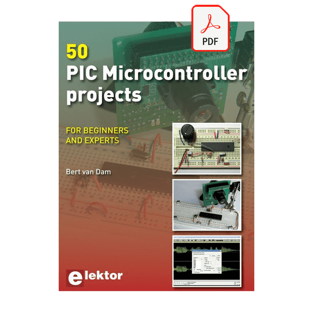
Elektor Digital 50 PIC Microcontroller Projects (E-book)
This book contains 50 fun and exciting projects for PIC microcontrollers such as a laser alarm, USB teasing mouse, eggtimer, youth repellent, soundswitch, capacitive liquid level gauge, 'finger in the water' sensor, guarding a room using a camera, mains light dimmer (110-240 volts), talking microcontroller and much more. Several different techniques are discussed such as relay, alternating current control including mains, I²C, SPI, RS232, USB, pulse width modulation, rotary encoder, interrupts, infrared, analog-digital conversion (and the other way around), 7-segment display and even CAN bus. You can use this book to build the projects for your own use. The clear explanations, schematics and even pictures of each project make this a fun activity. For each project the theory is discussed and why the project has been executed in that particular way. That means you can also use this book as a studybook, or as basis for larger and more complicated projects. All projects use a breadboard so modification and expansion is easy. Three PIC microcontrollers are used, the 16f877A, 18f4455 and 18f4685. It is also discussed how you can migrate your project from one microcontroller to another – 15 types are supported - including two example projects. All software that is used in this book can be downloaded for free. That also applies to the open source programming language JAL. This powerful and yet easy to learn language is used by hobbyists as well as professionals. This book can also be used as a reference guide. It explains all JAL commands, as well as the expansion libraries. Using the index you can easily find example projects that illustrate the use of these commands. Even when you have built all projects in this book you will still want to keep it within arm's reach.
€ 34,95
Mitglieder: € 31,46
-

Elektor Labs Elektor Rauscharmes Labornetzteil
Das rauscharme Labornetzteil von Elektor ist ein vollständig analoges, einstellbares, symmetrisches Gerät mittlerer Leistung, das ohne Schalt- oder digitale Komponenten auskommt. Es bietet eine Ausgangsspannung, die zwischen 0 V und ±22 V einstellbar ist, sowie einen Ausgangsstrom, der von 0 A bis 1 A eingestellt werden kann. Da auf jegliche Art von Schalttechnik verzichtet wird, liefert das Design extrem geringes Rauschen. Zur Anzeige beider Ausgangsspannungen und -ströme werden vier kleine analoge Einbauinstrumente mit Drehspulmesswerk verwendet. Die meisten modernen Labornetzgeräte und AC-Adapter arbeiten mit Schaltnetzteiltechnik. Selbst die besten Ausführungen weisen zwangsläufig hochfrequente Restwelligkeit und andere Schaltartefakte am Ausgang auf, die die Prüfung empfindlicher analoger Schaltungen stören und Messungen kleiner Signale beeinträchtigen können. Um dieses Problem zu vermeiden, setzt dieses Konzept auf ein vollständig analoges Netzgerät. Obwohl es weniger effizient ist als vergleichbare Schaltnetzteile, spielt die geringere Effizienz beim Einsatz auf dem Prüfstand kaum eine Rolle und sorgt für sauberere und zuverlässigere Messergebnisse. Da viele analoge Schaltungen eine symmetrische Versorgung benötigen, liefert dieses Design positive und negative Ausgangsspannungen gleicher Höhe. Eine geringfügige Nachjustierung ist möglich, um eventuelle Ungleichgewichte auszugleichen. Selbstverständlich ist auch eine einstellbare Strombegrenzung integriert. Das Kit enthält die für den Aufbau des Netzteils erforderlichen Komponenten, mit Ausnahme der Transformatoren. Technische Daten Ausgangsspannung 0…+22 V, 0, −22 V Ausgangsstrom 0…+1 A, 0…−1 A Rauschen −85 dBV (bei 0,95 A/20 V, B = 22 kHz) −84 dBV (bei 0,95 A/20 V, B > 500 kHz) Restwelligkeit 50 µVRMS (bei 950 mA/20 V, B = 22 kHz, hauptsächlich 100-Hz-Anteil) Lieferumfang 3x Platinen: Regler (PCB-1), Netzfilter (PCB-2) und Transformator (PCB-3) Alle Bauteile mit Ausnahme der Netztransformatoren 4x Drehspulmesswerke Zusätzliche Teile für die Verdrahtung (Drähte, Bananenbuchsen, Kaltgeräte-Netzmodul usw.) Nicht enthalten Die drei Netztransformatoren Ein Gehäuse Stückliste Für die Spannungsregler-Platine (240386-1) Widerstände (250 mW, 1%) R1 = 12 Ω R2, R8, R37, R62 = 1 MΩ R3, R7, R10, R13, R17, R20, R22, R30, R35, R42, R45, R47, R55, R60 = 100 Ω, 600 mW R4, R5 = 4.7 kΩ R6 = 100 kΩ R9, R12, R14, R36, R38, R39, R61, R63, R66, R72, R78, R79 = 10.0 kΩ, 600 mW R11 = 9.76 kΩ, 600 mW R15, R40 = 44.2 kΩ, 600 mW R16, R41, R77 = 1 kΩ R18, R43 = 1.5 kΩ, 1 W, 5% R19, R44 = 470 Ω, 1 W, 5% R21, R46 = 330 Ω, 600 mW R23, R24, R48, R49 = 1.0 Ω, 1 W R25, R50 = 1 kΩ, 1 W, 5% R26, R28, R51, R53 = 1.000 kΩ 0.1%, 15 ppm/C R27, R29, R52, R54 = 10.00 kΩ 0.1%, 15 ppm/C R31, R56 = 1.2 kΩ, 1 W, 5% R32, R57 = 47 kΩ R33, R58 = 270 Ω R34, R59 = 27 kΩ R64, R69 = 12.0 kΩ R65 = 3.0 kΩ, 600 mW R67, R80 = 470 Ω, 600 mW R68, R70 = 6.8 kΩ, 600 mW R71 = 30.0 kΩ,, 600 mW R73, R74, R75, R76 = 10 MΩ P1, P2, P3 = 10 kΩ, 200 mW, 20%, potentiometer, 1 turns, single, lin., panel mount P4, P5 = 500 Ω, 500 mW, 10%, trimmer, 25 turns, 3296Y-1-501LF Bourns P6, P7 = 10 kΩ, 500 mW, 10%, trimmer, 25 turns, 3296Y-1-501LF Bourns Kondensatoren C1 = 100 nF, 50 V, 10%, ceramic X7R, LS 5 mm C2, C3, C6, C7, C30 = 10 µF, 63V, 20%, LS 2.5 mm, 3000hours@105°C C4, C5, C8, C9, C13, C14, C18, C19, C23, C24, C28, C29, C31, C32, C38, C39 = 100 nF, 250 V, 10%, PET, LS 7.5 mm C10, C20 = 47 nF, 100 V, 5%, PET, LS 5 mm C11, C21 = 10 nF, 100 V, 5%, PET, LS 5 mm C12, C22 = 220 µF, 35 V, 20%, 0.024 Ω, LS2.5/3.5 mm, Ir 3.4 A, 2000hours@125°C, polymer C15, C25 = 120 µF, 50 V, 20%, ESR 0.02 Ω, Diam. 10 mm max., LS 5 mm C16, C26 = 15 nF, 100 V, 5%, PET, LS 5 mm C17, C27 = 47 nF, 100 V, 5%, PET, LS 5 mm C33, C34 = 22 µF, 50 V, 20%, LS 2 mm, 10000 hours @ 105°C C35, C36, C44, C45 = 1 µF, 100 V, 10%, LS 5 mm, ceramic X7R C37 = 100 uF, 50 V, 20%. LS 3.5 mm C40, C41, C42, C43, C46, C47, C48, C49 = 1000 µF, 50 V, 20%, LS 5/7.5 mm, Ir 3.32 A, 10000hours@105°C, D 16 mm C50, C51, C52, C53 = 47 nF, 100 V, 10%, ceramic X7R, LS 5 mm Induktivitäten L1, L2 = 4.7 µH, 3.2 A, 0.033 Ω, LS 5 mm, RLB0914-4R7ML Bourns L3 = Commom mode choke, 14.5 mH, 3 A, SSRH24NH-30145 Kemet Halbleiter D1, D2, D3, D4, D5, D9, D10, D11, D15 = BAT85, DO-34 D6, D7, D12, D13 = SR560, DO-201AD D8, D14, D16 = 1N4148, DO-35 D17 = Zenerdiode, 5.6 V, 0.5 W, DO-41 D18, D19 = 1N4004, DO-41 D20, D21 D22, D23 = V30100CI-M3/P, dual common cathode, TO-220 D24 = Zener diode, 30 V, 1 W, DO-41 LED1, LED2 = LED, red, T-1 (3 mm) LED3, LED4 = LED, green, T-1 (3 mm) TVS1, TVS2 = BZW50-33B, R6 T1, T2, T4 = BC337.25, TO-92 T3 = NJW0302G, TO-3P T5, T6, T8 = BC327.25, TO-92 T7 = NJW0281G, TO-3P T9 = BD139, TO-126 (SOT-32) IC1 = LM334Z, TO-92 IC2 = LM4040AIZ-5.0/NOPB, TO-92 (TO-226AA-3) IC3, IC4 = OPA2992IDR, SOIC-8 IC5, IC6 = OPA4992IDR, SOIC-14 IC7 = OPA992IDBVR, SOT-23-5 IC8 = LM339N, DIP-14 IC9 = LM317, TO-220 IC10 = LM337, TO-220 Sonstiges F1, F2 = 5×20 mm fuse, 1.6 A, fast acting HS1, HS2 = Heatsink MC33271 (for T3/T7), 2.7°C/W, PCB mount, height 63.5 mm K1, K4 = 3-way screw terminal block, LS 3.5 mm, max. 1.5 mm² K2, K3 = 3-way screw terminal block, LS 3.5 mm, max. 1 mm² M1, M3 = Moving coil meter, Range 30 V, type 91C4, 45×45 mm M2, M4 = Moving coil meter, Range 1 A, type 91C4, 45×45 mm² RE1 = Relay DPDT,5V, UA2-5NU Verschiedenes 3× 3-way screw terminal block, LS 3.5 mm, max. 1 mm² (for P1, P2, P3) 4× Pin header, 1×2, vertical, pitch 2.54 mm (for LED1, LED2, LED3, LED4) 4× Pin socket, 1×2, vertical. pitch 2.54 mm (for LED1, LED2, LED3, LED4) 2× Heatsink FK222SA220, 20°C/W, PCB mount (for IC9 & IC10) 2× Mica thermal pad for TO-220, 12×18×0.05 mm (for IC9 & IC10) 2× Insulating bushing IB 6, TO-220 (for IC9 & IC10) 2× Ceramic thermal pad, 23×20×2 mm (for T3 & T7) 2× PCB Fuse Holder, for 5×20 mm fuse, 10 A (for F1, F2) 2× Cover for PCB Fuse Holder, transparent (for F1, F2) 2× 2-way screw terminal block, LS 3.5 mm, max. 1 mm² (for M1 & M3) 2× 2-way screw terminal block, LS 3.5 mm, max. 1.5 mm² (for M2 & M4) 8× M3 solder lug, thickness 0.35 mm (for M1…M4) M4 solder lug, thickness 0.35 mm (to connect 4 mm banana connectors) Screened cable, 1 pair, 2×24 AWG/0.22 mm², 1 m (for P1, P2 & P3) IC socket, DIP, 14 contacts (for IC8) M3 washer, plain, steel M3 screw, 16 mm, steel, pan head M3 nut M3 spring washer 50 mm M3 standoff, steel, male-female 12 mm M3 standoff, steel, male-female 10 mm M3 standoff, steel, male-female M3 screw, 8 mm, steel, pan head Für die Netzfilter-Platine (240386-2) Widerstand R1 = 220 kΩ, 1 W, 500 V, 5% Kondensatoren C1, C2 = 470 nF, 305 VAC, Class X2, 11 × 27 mm max., LS 15/22.5 mm C3, C4, C5, C6 = 2.2 nF, 300 VAC, Class Y2, 13 × 4 mm, LS 10 mm, PP Induktivitäten L1, L2 = Common-mode choke, 6.8 mH, 1.7 A, TDK B82732R2172B030 Halbleiter MOV1 = TVS varistor, 300 VAC, S14K300 (230 VAC, B72214S0301K101) and SK14K150 (150 VAC, B72214S0151K101) Sonstiges K1, K2 = 3-way screw terminal block, LS 7.62 mm F1 = Time-delay fuse, 0.5 A (230 VAC) or 1 A (115 VAC) Verschiedenes 1× Fuse holder, 5×20 mm, 10 A, 500 VAC 1× Transparent fuse cover 4× 10 mm M3 standoff, steel, male–female 4× M3 screw, 8 mm, steel, pan head 4× M3 nut Für die Transformator-Platine (240386-3) Widerstände R1, R2 = 2.7 kΩ, 600 mW, 1% R3 = 10.0 kΩ, 600 mW, 1% Kondensator C1 = 220 µF, 50 V, 20%, Ø10 mm, LS 5 mm, 4000 h @ 105°C Transformatoren (nicht im Lieferumfang dieses Kits enthalten!) TR1, TR2, TR3 = 2×7 V, 25 VA, PCB-mounted toroid, 70060K Talema Halbleiter D1–D4 = 1N4148, DO-35 D5, D6 = 1N4004, DO-41 D7 = Zener 5.6 V, 1.3 W, DO-41 LED1 = LED, red, T-1 (3 mm) IC1, IC2 = MOC8021M, CTR ≥ 1000%, DIP-6 Sonstiges F1, F2, F3 = 160 mA time-delay fuse (230 VAC) or 315 mA time-delay fuse (115 VAC) K1 = 2-way screw terminal block, LS 7.62 mm K2 = 3-way screw terminal block, LS 3.5 mm, max 1.5 mm² K3, K4 = 3-way screw terminal block, LS 3.5 mm, max 1 mm² RE1, RE2 = Relay DPDT, 5 A/250 VAC / 24 VDC Verschiedenes 1× Pin header 1×2, pitch 2.54 mm + matching socket for LED1 3× Fuse holder 5 × 20 mm, 10 A, 500 VAC + transparent cover 3× M4 screw, 8 mm, pan head + washer for TR1-TR3 8× M3 screw, 8 mm, pan head + nut + washer 8× 10 mm M3 standoff, steel, male–female 2× IC socket, DIP-6 for IC1 & IC2 Weitere Bauteile 1 m red insulated wire, stranded, 1.5 mm² 0.5 m blue insulated wire, stranded, 1.5 mm² 0.5 m black insulated wire, stranded, 1.5 mm², 0.5 m 2 m red insulated wire, stranded, D 0.56 mm (0.25 mm²) 2 m black insulated wire, stranded, D 0.56 mm (0.25 mm²) 0.5 m Multicore Cable, Flexible, 3 Core, 0.75 mm² (24 x 0.2 mm) Red banana socket Black banana socket Blue banana socket Green banana socket IEC Power Entry Module with switch, IEC C14 3 crimp terminals, FASTON, 4.75 x 0.81 mm 3 knobs Links Elektor Labs JumpStarter Page Artikel (Teil 1) Artikel (Teil 2)
€ 299,00€ 249,00Bestpreis
-

Elektor Digital Elektor September/Oktober 2023 (PDF)
Der vollständige Download dieser Nummer ist für unsere GOLD- und GREEN-Mitglieder auf der Elektor Magazine- Site verfügbar! Nicht noch einmal Mitglied? Klicken Sie hier . Raspberry Pi Pico als Spektrumanalysator der FFT mit gut handelbarem Material linearer Spannungsregler ±40 V eine hochwertige Stromversorgung für den Leistungsverstärker Fortissimo-100 … und andere! Die Kommunikation ohne Mikrocontroller wird flexibel Das EEPROM bietet Möglichkeiten zur Netzwerkinstallation für Mikrocontroller ohne Kabel 5000 ? zu gewinnen! Nehmen Sie am STM32 Wireless Innovation Design Contest teil 2023: Die Odyssee der IA Starten Sie mit dem ChatGPT-Codeinterpreter LoRa, ein Schweizer Messer (1) das LoRa-Protokoll und seine Vorteile einstellbare Stromstärke mit integriertem Uhrengenerator Testen Sie Ihre Stromversorgung, Spannungswandler und Batterien die neuen Arduino UNO R4 Minima- und WiFi-Karten von logarithmischen Potentiometern das sind Exponentiale! Schnittstellenkarte für Motorsteuerung Ein BoB für einen 5 A Dauerläufermotor mit einer Größe von 3×3 mm über die Lebensgefahr der Elektronik Bietet eine Mobilfunkarchitektur ihnen den geringsten Nutzen für das Objekt-Internet (IdO)? Energieeffizienzmerkmale der LTE-M- und NB-IoT-Technologien für den Einsatz von Niedrigenergienetzen (LPWAN) Drahtlose Kommunikation in IoT-Systemen mithilfe von Arduino MKR-Modulen Kommunikationsnormen für Arduino-Module für IoT bereit für alternativen Strom in den magnetischen Komponenten Vermeiden Sie die Überhitzung der Induktivitäten! Optimieren Sie die Cloud-Bereitstellung mit maßgefertigten Geräten Matter-Implementierung: Was muss ich tun, um Matter-Geräte bereitzustellen? der YARD Stick One ein drahtloses Testwerkzeug für Frequenzen bis zu 1 GHz verriegeltes Relais Drôle de Composant, die Serie Bild Uhr? nimm die Pouls der Zeit Konzeption eines SDR-Sendezeitempfängers Sorgfaltspflichtrichtlinie „Weiter so“ ist nicht genug Starten mit elektronischem Spannungsverstärker Infrarot-Sensoren mit Arduino Pro Mini ein Projektauszug aus dem Buch „Arduino & Co.“ von Elektor Cloudbasierter Energierechner mit einem ESP32-Modul und einem Spannungs-/Stromsensor PZEM-004T Anleitung zur Bare-Metal-Programmierung (2) Präzisions-Timer, UART und Debugging Hexadoku
€ 10,95


