
Suchergebnisse für "the OR arduino OR inside OR measurement OR lab"
-

Elektor Labs Elektor Rauscharmes Labornetzteil
Das rauscharme Labornetzteil von Elektor ist ein vollständig analoges, einstellbares, symmetrisches Gerät mittlerer Leistung, das ohne Schalt- oder digitale Komponenten auskommt. Es bietet eine Ausgangsspannung, die zwischen 0 V und ±22 V einstellbar ist, sowie einen Ausgangsstrom, der von 0 A bis 1 A eingestellt werden kann. Da auf jegliche Art von Schalttechnik verzichtet wird, liefert das Design extrem geringes Rauschen. Zur Anzeige beider Ausgangsspannungen und -ströme werden vier kleine analoge Einbauinstrumente mit Drehspulmesswerk verwendet. Die meisten modernen Labornetzgeräte und AC-Adapter arbeiten mit Schaltnetzteiltechnik. Selbst die besten Ausführungen weisen zwangsläufig hochfrequente Restwelligkeit und andere Schaltartefakte am Ausgang auf, die die Prüfung empfindlicher analoger Schaltungen stören und Messungen kleiner Signale beeinträchtigen können. Um dieses Problem zu vermeiden, setzt dieses Konzept auf ein vollständig analoges Netzgerät. Obwohl es weniger effizient ist als vergleichbare Schaltnetzteile, spielt die geringere Effizienz beim Einsatz auf dem Prüfstand kaum eine Rolle und sorgt für sauberere und zuverlässigere Messergebnisse. Da viele analoge Schaltungen eine symmetrische Versorgung benötigen, liefert dieses Design positive und negative Ausgangsspannungen gleicher Höhe. Eine geringfügige Nachjustierung ist möglich, um eventuelle Ungleichgewichte auszugleichen. Selbstverständlich ist auch eine einstellbare Strombegrenzung integriert. Das Kit enthält die für den Aufbau des Netzteils erforderlichen Komponenten, mit Ausnahme der Transformatoren. Technische Daten Ausgangsspannung 0…+22 V, 0, −22 V Ausgangsstrom 0…+1 A, 0…−1 A Rauschen −85 dBV (bei 0,95 A/20 V, B = 22 kHz) −84 dBV (bei 0,95 A/20 V, B > 500 kHz) Restwelligkeit 50 µVRMS (bei 950 mA/20 V, B = 22 kHz, hauptsächlich 100-Hz-Anteil) Lieferumfang 3x Platinen: Regler (PCB-1), Netzfilter (PCB-2) und Transformator (PCB-3) Alle Bauteile mit Ausnahme der Netztransformatoren 4x Drehspulmesswerke Zusätzliche Teile für die Verdrahtung (Drähte, Bananenbuchsen, Kaltgeräte-Netzmodul usw.) Nicht enthalten Die drei Netztransformatoren Ein Gehäuse Stückliste Für die Spannungsregler-Platine (240386-1) Widerstände (250 mW, 1%) R1 = 12 Ω R2, R8, R37, R62 = 1 MΩ R3, R7, R10, R13, R17, R20, R22, R30, R35, R42, R45, R47, R55, R60 = 100 Ω, 600 mW R4, R5 = 4.7 kΩ R6 = 100 kΩ R9, R12, R14, R36, R38, R39, R61, R63, R66, R72, R78, R79 = 10.0 kΩ, 600 mW R11 = 9.76 kΩ, 600 mW R15, R40 = 44.2 kΩ, 600 mW R16, R41, R77 = 1 kΩ R18, R43 = 1.5 kΩ, 1 W, 5% R19, R44 = 470 Ω, 1 W, 5% R21, R46 = 330 Ω, 600 mW R23, R24, R48, R49 = 1.0 Ω, 1 W R25, R50 = 1 kΩ, 1 W, 5% R26, R28, R51, R53 = 1.000 kΩ 0.1%, 15 ppm/C R27, R29, R52, R54 = 10.00 kΩ 0.1%, 15 ppm/C R31, R56 = 1.2 kΩ, 1 W, 5% R32, R57 = 47 kΩ R33, R58 = 270 Ω R34, R59 = 27 kΩ R64, R69 = 12.0 kΩ R65 = 3.0 kΩ, 600 mW R67, R80 = 470 Ω, 600 mW R68, R70 = 6.8 kΩ, 600 mW R71 = 30.0 kΩ,, 600 mW R73, R74, R75, R76 = 10 MΩ P1, P2, P3 = 10 kΩ, 200 mW, 20%, potentiometer, 1 turns, single, lin., panel mount P4, P5 = 500 Ω, 500 mW, 10%, trimmer, 25 turns, 3296Y-1-501LF Bourns P6, P7 = 10 kΩ, 500 mW, 10%, trimmer, 25 turns, 3296Y-1-501LF Bourns Kondensatoren C1 = 100 nF, 50 V, 10%, ceramic X7R, LS 5 mm C2, C3, C6, C7, C30 = 10 µF, 63V, 20%, LS 2.5 mm, 3000hours@105°C C4, C5, C8, C9, C13, C14, C18, C19, C23, C24, C28, C29, C31, C32, C38, C39 = 100 nF, 250 V, 10%, PET, LS 7.5 mm C10, C20 = 47 nF, 100 V, 5%, PET, LS 5 mm C11, C21 = 10 nF, 100 V, 5%, PET, LS 5 mm C12, C22 = 220 µF, 35 V, 20%, 0.024 Ω, LS2.5/3.5 mm, Ir 3.4 A, 2000hours@125°C, polymer C15, C25 = 120 µF, 50 V, 20%, ESR 0.02 Ω, Diam. 10 mm max., LS 5 mm C16, C26 = 15 nF, 100 V, 5%, PET, LS 5 mm C17, C27 = 47 nF, 100 V, 5%, PET, LS 5 mm C33, C34 = 22 µF, 50 V, 20%, LS 2 mm, 10000 hours @ 105°C C35, C36, C44, C45 = 1 µF, 100 V, 10%, LS 5 mm, ceramic X7R C37 = 100 uF, 50 V, 20%. LS 3.5 mm C40, C41, C42, C43, C46, C47, C48, C49 = 1000 µF, 50 V, 20%, LS 5/7.5 mm, Ir 3.32 A, 10000hours@105°C, D 16 mm C50, C51, C52, C53 = 47 nF, 100 V, 10%, ceramic X7R, LS 5 mm Induktivitäten L1, L2 = 4.7 µH, 3.2 A, 0.033 Ω, LS 5 mm, RLB0914-4R7ML Bourns L3 = Commom mode choke, 14.5 mH, 3 A, SSRH24NH-30145 Kemet Halbleiter D1, D2, D3, D4, D5, D9, D10, D11, D15 = BAT85, DO-34 D6, D7, D12, D13 = SR560, DO-201AD D8, D14, D16 = 1N4148, DO-35 D17 = Zenerdiode, 5.6 V, 0.5 W, DO-41 D18, D19 = 1N4004, DO-41 D20, D21 D22, D23 = V30100CI-M3/P, dual common cathode, TO-220 D24 = Zener diode, 30 V, 1 W, DO-41 LED1, LED2 = LED, red, T-1 (3 mm) LED3, LED4 = LED, green, T-1 (3 mm) TVS1, TVS2 = BZW50-33B, R6 T1, T2, T4 = BC337.25, TO-92 T3 = NJW0302G, TO-3P T5, T6, T8 = BC327.25, TO-92 T7 = NJW0281G, TO-3P T9 = BD139, TO-126 (SOT-32) IC1 = LM334Z, TO-92 IC2 = LM4040AIZ-5.0/NOPB, TO-92 (TO-226AA-3) IC3, IC4 = OPA2992IDR, SOIC-8 IC5, IC6 = OPA4992IDR, SOIC-14 IC7 = OPA992IDBVR, SOT-23-5 IC8 = LM339N, DIP-14 IC9 = LM317, TO-220 IC10 = LM337, TO-220 Sonstiges F1, F2 = 5×20 mm fuse, 1.6 A, fast acting HS1, HS2 = Heatsink MC33271 (for T3/T7), 2.7°C/W, PCB mount, height 63.5 mm K1, K4 = 3-way screw terminal block, LS 3.5 mm, max. 1.5 mm² K2, K3 = 3-way screw terminal block, LS 3.5 mm, max. 1 mm² M1, M3 = Moving coil meter, Range 30 V, type 91C4, 45×45 mm M2, M4 = Moving coil meter, Range 1 A, type 91C4, 45×45 mm² RE1 = Relay DPDT,5V, UA2-5NU Verschiedenes 3× 3-way screw terminal block, LS 3.5 mm, max. 1 mm² (for P1, P2, P3) 4× Pin header, 1×2, vertical, pitch 2.54 mm (for LED1, LED2, LED3, LED4) 4× Pin socket, 1×2, vertical. pitch 2.54 mm (for LED1, LED2, LED3, LED4) 2× Heatsink FK222SA220, 20°C/W, PCB mount (for IC9 & IC10) 2× Mica thermal pad for TO-220, 12×18×0.05 mm (for IC9 & IC10) 2× Insulating bushing IB 6, TO-220 (for IC9 & IC10) 2× Ceramic thermal pad, 23×20×2 mm (for T3 & T7) 2× PCB Fuse Holder, for 5×20 mm fuse, 10 A (for F1, F2) 2× Cover for PCB Fuse Holder, transparent (for F1, F2) 2× 2-way screw terminal block, LS 3.5 mm, max. 1 mm² (for M1 & M3) 2× 2-way screw terminal block, LS 3.5 mm, max. 1.5 mm² (for M2 & M4) 8× M3 solder lug, thickness 0.35 mm (for M1…M4) M4 solder lug, thickness 0.35 mm (to connect 4 mm banana connectors) Screened cable, 1 pair, 2×24 AWG/0.22 mm², 1 m (for P1, P2 & P3) IC socket, DIP, 14 contacts (for IC8) M3 washer, plain, steel M3 screw, 16 mm, steel, pan head M3 nut M3 spring washer 50 mm M3 standoff, steel, male-female 12 mm M3 standoff, steel, male-female 10 mm M3 standoff, steel, male-female M3 screw, 8 mm, steel, pan head Für die Netzfilter-Platine (240386-2) Widerstand R1 = 220 kΩ, 1 W, 500 V, 5% Kondensatoren C1, C2 = 470 nF, 305 VAC, Class X2, 11 × 27 mm max., LS 15/22.5 mm C3, C4, C5, C6 = 2.2 nF, 300 VAC, Class Y2, 13 × 4 mm, LS 10 mm, PP Induktivitäten L1, L2 = Common-mode choke, 6.8 mH, 1.7 A, TDK B82732R2172B030 Halbleiter MOV1 = TVS varistor, 300 VAC, S14K300 (230 VAC, B72214S0301K101) and SK14K150 (150 VAC, B72214S0151K101) Sonstiges K1, K2 = 3-way screw terminal block, LS 7.62 mm F1 = Time-delay fuse, 0.5 A (230 VAC) or 1 A (115 VAC) Verschiedenes 1× Fuse holder, 5×20 mm, 10 A, 500 VAC 1× Transparent fuse cover 4× 10 mm M3 standoff, steel, male–female 4× M3 screw, 8 mm, steel, pan head 4× M3 nut Für die Transformator-Platine (240386-3) Widerstände R1, R2 = 2.7 kΩ, 600 mW, 1% R3 = 10.0 kΩ, 600 mW, 1% Kondensator C1 = 220 µF, 50 V, 20%, Ø10 mm, LS 5 mm, 4000 h @ 105°C Transformatoren (nicht im Lieferumfang dieses Kits enthalten!) TR1, TR2, TR3 = 2×7 V, 25 VA, PCB-mounted toroid, 70060K Talema Halbleiter D1–D4 = 1N4148, DO-35 D5, D6 = 1N4004, DO-41 D7 = Zener 5.6 V, 1.3 W, DO-41 LED1 = LED, red, T-1 (3 mm) IC1, IC2 = MOC8021M, CTR ≥ 1000%, DIP-6 Sonstiges F1, F2, F3 = 160 mA time-delay fuse (230 VAC) or 315 mA time-delay fuse (115 VAC) K1 = 2-way screw terminal block, LS 7.62 mm K2 = 3-way screw terminal block, LS 3.5 mm, max 1.5 mm² K3, K4 = 3-way screw terminal block, LS 3.5 mm, max 1 mm² RE1, RE2 = Relay DPDT, 5 A/250 VAC / 24 VDC Verschiedenes 1× Pin header 1×2, pitch 2.54 mm + matching socket for LED1 3× Fuse holder 5 × 20 mm, 10 A, 500 VAC + transparent cover 3× M4 screw, 8 mm, pan head + washer for TR1-TR3 8× M3 screw, 8 mm, pan head + nut + washer 8× 10 mm M3 standoff, steel, male–female 2× IC socket, DIP-6 for IC1 & IC2 Weitere Bauteile 1 m red insulated wire, stranded, 1.5 mm² 0.5 m blue insulated wire, stranded, 1.5 mm² 0.5 m black insulated wire, stranded, 1.5 mm², 0.5 m 2 m red insulated wire, stranded, D 0.56 mm (0.25 mm²) 2 m black insulated wire, stranded, D 0.56 mm (0.25 mm²) 0.5 m Multicore Cable, Flexible, 3 Core, 0.75 mm² (24 x 0.2 mm) Red banana socket Black banana socket Blue banana socket Green banana socket IEC Power Entry Module with switch, IEC C14 3 crimp terminals, FASTON, 4.75 x 0.81 mm 3 knobs Links Elektor Labs JumpStarter Page Artikel (Teil 1) Artikel (Teil 2)
€ 299,00€ 249,00Bestpreis
-
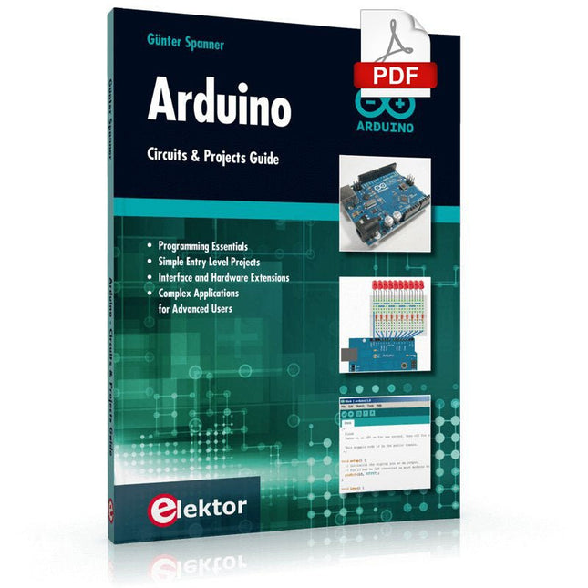
Elektor Digital Arduino – Circuits & Projects Guide (E-book)
Two reasons can be identified for the immense success of the Arduino platform. First, the cheap, ready to go processor board greatly simplifies the introduction to hardware. The second success factor is the free and open-source programming suite that does not require an installation procedure. Simple entry-level examples ensure rapid successes. Complex selection procedures for parameters like the microprocessor version or interface settings are not required. The first sample programs can be uploaded to the Arduino board, and tested, in a matter of minutes. The Arduino user is supported by an array of software libraries. However, the daily increasing volume of libraries poses initial problems to the newcomer, and the way ahead may be uncertain after a few entry-level examples. In many cases, detailed descriptions are missing, and poorly described projects tend to confuse rather than elucidate. Clear guidance and a single motto are missing, usually owing to the projects having been created by several different persons—all with different aims in mind. This book represents a different approach. All projects are presented in a systematical manner, guiding into various theme areas. In the coverage of must-know theory great attention is given to practical directions users can absorb, including essential programming techniques like A/D conversion, timers and interrupts—all contained in the hands-on projects. In this way readers of the book create running lights, a wakeup light, fully functional voltmeters, precision digital thermometers, clocks of many varieties, reaction speed meters, or mouse controlled robotic arms. While actively working on these projects the reader gets to truly comprehend and master the basics of the underlying controller technology.
€ 29,95
Mitglieder: € 26,96
-

Red Pitaya Red Pitaya STEMlab 125-14 PRO Gen 2 Starter Kit (inkl. Buch)
Dieses Bundle enthält das Red Pitaya STEMlab 125-14 PRO Gen 2 Starter Kit und das neue Buch "Experimenting with Red Pitaya STEMlab Gen 2". Das Red Pitaya STEMlab 125-14 PRO Gen 2 Starter Kit ist eine leistungsstarke und flexible Plattform für Signalverarbeitung, Datenerfassung und elektronische Messanwendungen. Dieses Kit wurde für Ingenieure, Entwickler, Forscher und Dozenten konzipiert und bietet alles, was für den Einstieg in die Entwicklung fortschrittlicher Mess- und Steuerungssysteme erforderlich ist. Das Herzstück des Kits ist das STEMlab 125-14 PRO Gen 2-Board, eine verbesserte und ultraleichte Entwicklungsplatine. Angetrieben vom Xilinx Zynq-7010 SoC mit 512 MB RAM kombiniert es die Programmierbarkeit eines FPGAs mit der Rechenleistung eines ARM-Prozessors, um leistungsstarke Messtechnik und kundenspezifische Signalverarbeitungslösungen zu ermöglichen. Das Board bietet eine 14-Bit-ADC- und DAC-Auflösung, eine Abtastrate von 125 MS/s, einen Eingangsbereich von ±20 V und eine Bandbreite von bis zu 60 MHz. Dank seines verbesserten rauscharmen analogen Frontends, der USB-C-Konnektivität und des kompakten Designs eignet es sich für anspruchsvolle Anwendungen wie HF-Entwicklung, Radarsysteme, Photonikforschung, Software-Defined Radio (SDR) und industrielle Automatisierung. Das Starter Kit enthält alles notwendige Zubehör für den sofortigen Einsatz: eine microSD-Karte mit vorinstalliertem Betriebssystem, ein Netzteil, ein Ethernet-Kabel für den Fernzugriff, zwei 100-MHz-Oszilloskop-Messspitzen sowie SMA-zu-BNC-Adapter für flexible Signalanschlüsse. Das Red Pitaya STEMlab 125-14 PRO Gen 2 Starter Kit ist eine hervorragende Plattform für Rapid Prototyping, FPGA-Entwicklung, Messtechnik und fortgeschrittene Elektronikversuche. Features 14-Bit-ADC- und DAC-Auflösung Abtastrate: 125 MS/s Eingangsspannungsbereich: ±20 V Bandbreite: Bis zu 60 MHz Xilinx Zynq-7010 SoC (FPGA + ARM-Prozessor) 512 MB RAM Rauscharme analoge Front- und Backends Anwendungen HF-Entwicklung und -Test Radar- und drahtlose Systeme Software Defined Radio (SDR) Photonik und optische Forschung Industrielle Automatisierungs- und Steuerungssysteme Signalanalyse und -instrumentierung Schnelles Prototyping elektronischer Bauteile Messsysteme Technische Daten Prozessor Dual-Core ARM Cortex-A9 FPGA AMD Xilinx Zynq-7010 SoC RAM 512 MB (4 Gb) Speicher microSD-Karte (bis zu 32 GB) Betriebssystem Linux-basiertes Red Pitaya OS ADC-Auflösung 14 Bit DAC Auflösung 14 Bit Bandbreite 60 MHz (DC) Abtastrate 125 MS/s Analoge Eingangskanäle 2 Analoge Ausgangskanäle 2 Eingangsspannungsbereich ±1 V (LV) / ±20 V (HV) Eingangsimpedanz 1 MΩ / 10 pF Ausgangsspannungsbereich ±1 V Ethernet 1x Gigabit Ethernet (RJ45) USB 2x USB-C 2.0 (für Stromversorgung und Konsole) Digitale Ein-/Ausgänge 16x GPIO (3,3 V) Kommunikationsschnittstellen I²C, SPI, UART, CAN Stromversorgung 5 V/3 A über USB-C Abmessungen 106,8 x 60,0 x 17,9 mm Lieferumfang 1x Red Pitaya STEMlab 125-14 PRO Gen 2 Board 2x 100-MHz-Oszilloskop-Tastköpfe 2x SMA-zu-BNC-Adapter 1x microSD-Karte mit vorinstalliertem Betriebssystem 1x USB-C-Netzteil 1x Ethernet-Kabel Downloads Documentation Schematics Buch: Experimenting with Red Pitaya STEMlab Gen 2 Mit diesem neuen Buch geht Red Pitaya über ein vielseitiges Board hinaus – es wird zu einem leistungsstarken Laborinstrument für präzise Messungen, Analysen und Steuerungen. Von den Grundlagen der Entwicklung elektronischer Projekte über Überwachung, Regelung und Design bis hin zu Tests führt Sie dieses Buch Schritt für Schritt durch alles, was Sie wissen müssen, um das volle Potenzial der Red Pitaya-Hardware und -Software auszuschöpfen. Das Buch stellt Echtzeitprojekte auf FPGA-Basis vor, die auf einem PC mit der Vivado-Umgebung entwickelt und anschließend zur Ausführung und zum Testen auf die Red Pitaya übertragen werden. Sie lernen mehr über gesteigerte Leistung, erweiterte I/O-Möglichkeiten, verbesserte FPGA-Funktionen sowie fortschrittliche Konnektivitätsoptionen, die neue Möglichkeiten für präzise Messungen, Überwachung und Steuerung in Ihren Embedded-Anwendungen eröffnen. Im Buch entdecken Sie: Einen tiefgehenden Einblick in die Red Pitaya-Architektur und das Hardware-Design Elektronische Experimente mit Red Pitaya für Mess- und Überwachungsanwendungen Praxisnahe Projekte mit der Programmiersprache Python Praktische Anleitungen zur FPGA-Programmierung mit Red Pitaya Red Pitaya FPGA-Projekte mit Verilog HDL in der Vivado IDE Die praxisorientierte Entwicklung elektronischer Projekte inklusive Messung und Tests Schritt-für-Schritt-Beispiele, die Theorie und reale Umsetzung miteinander verbinden Ganz gleich, ob Sie eigene elektronische Schaltungen entwerfen, Werkzeuge zur Signalanalyse entwickeln oder Echtzeit-Steuerungs- und Überwachungssysteme erstellen – dieses Buch vermittelt Ihnen das nötige Wissen und die Sicherheit, um die Red Pitaya-Plattform vollständig zu verstehen und individuell anzupassen.
€ 799,00
Bestpreis
-
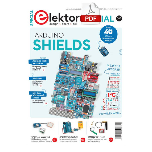
Elektor Digital Elektor Special: Arduino Shields (PDF)
Verwirklichen Sie Ihre Projekt-Träume: Der Kilometerzähler fürs Hamsterrad, eine vollautomatische Steuerung Ihrer Ameisenfarm mit Webinterface, oder den Sandwich-O-Mat – eine Maschine, die Sandwich-Toasts nach Wahl belegt und überbackt. Mit Arduino und der DIY- oder Maker-Bewegung wurde nicht nur der Einstieg in die Mikrocontroller-Programmierung kinderleicht, auch eine zweite Entwicklung fand statt: Viele Entwickler bringen kleine Boards – sogenannte Shields oder Module – auf den Markt, die den Einsatz zusätzlicher Hardware stark vereinfachten. Die kleinen Baugruppen enthalten alle wichtigen elektronischen Teile, um mit ein paar Steckkabeln an den Mikrocontroller angeschlossen zu werden, so dass ein frickeliger und aufwändiger Aufbau auf dem Steckboard entfällt. Zudem ist es so möglich, auch winzige kleine Bauteile zur Hand zu haben, die keine Anschlussbeinchen mehr haben (sogenannte SMDs). Enthaltene Projekte Arduino sucht Anschluss BMP, Einführung in Bibliotheken und I²C Mit den Mehrzweck-Shield I/O-Grundlagen kennenlernen I²C-LCD-Adapter und Punktmatrixanzeigen LCD-Tastaturschutz Level-Konverter W5100: Internetanbindung I/O-Erweiterungs-Shields Relais und Solid-State-Relais Das Multi-Funktions-Shield: eine universelle Bedieneinheit SD-Kartenleser über SPI anbinden Tasten und 7-Segmentanzeigen 16-Bit-ADC DAC MCP4725 16-fach PWM Servo-Treiber MP3-Player GPS-Datenlogger mit SD-Karte Berührungssensor Joystick SHT31: Temperatur und Luftfeuchtigkeit UV A-Sensor VEML6070 VL53L0X Flugzeit Ultraschallsensor-Entfernungsmesser LED-Punktmatrixanzeige mit MAX7219 Echtzeituhr DS3231 Port-Expander MCP23017 433 MHz Funk MPU-650: Gyroskop Beschleunigungssensor ADXL345 WS2812 RGB-LEDs Spannungsversorgung MQ-xx Gassensoren CO2-Gassensor ACS712 Stromstärkesensor INA219 Stromstärkesensor L298 Motortreiber RFID-Modul MFRC522 28BYJ-48 Schrittmotor TMC2209 Leiser Trittschalter X9C10x Digitales Poti Farb-TFT-Display mit ST7735 E-Paper-Anzeige Bluetooth Geigerzähler SIM800L GSM-Modul I²C-Multiplexer Controller Area Network
€ 11,90
Mitglieder: € 10,71
-

Elektor Publishing Hands-on Microcontroller Course for Advanced Arduino Users
32 new Projects, Practical Examples and Exercises with the Elektor Arduino Nano MCCAB Training Board Electronics and microcontroller technology offer the opportunity to be creative. This practical microcontroller course provides you with the chance to bring your own Arduino projects and experience such moments of success. Ideally, everything works as you imagined when you switch it on for the first time. In practice, however, things rarely work as expected. At that point, you need knowledge to efficiently search for and find the reason for the malfunction. In this book for advanced users, we delve deep into the world of microcontrollers and the Arduino IDE to learn new procedures and details, enabling you to successfully tackle and solve even more challenging situations. With this book, the author gives the reader the necessary tools to create projects independently and also to be able to find errors quickly. Instead of just offering ready-made solutions, he explains the background, the hardware used, and any tools required. He sets tasks in which the reader contributes their own creativity and writes the Arduino sketch themselves. If you don’t have a good idea and get stuck, there is, of course, a suggested solution for every project and every task, along with the corresponding software, which is commented on and explained in detail in the book. This practical course will teach you more about the inner workings of the Arduino Nano and its microcontroller. You will get to know hardware modules that you can use to realize new and interesting projects. You will familiarize yourself with software methods such as ‘state machines,’ which can often be used to solve problems more easily and clearly. The numerous practical projects and exercise sketches are once again realized on the Arduino Nano MCCAB Training Board, which you may already be familiar with from the course book ‘Microcontrollers Hands-on Course for Arduino Starters’, and which contains all the hardware peripherals and operating elements we need for the input/output operations of our sketches. Readers who do not yet own the Arduino Nano MCCAB Training Board can purchase the required hardware separately, or alternatively, build it on a breadboard.
€ 49,95€ 39,95Bestpreis
-
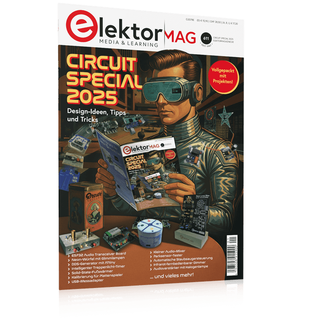
Elektor Circuit Special 2025 (DE)
Diese Ausgabe steht allen GOLD- und GREEN-Mitgliedern auf der ElektorMagazine-Website zum Download bereit! Sie sind noch kein Mitglied? Hier klicken! USB-MessadapterStrom und Signalqualität von USB-Anschlüssen testen 4...20 mA Stromausgang für Arduino UnoEine zuverlässige, EMI-unempfindliche Stromschleifenschnittstelle Automatische StaubsaugersteuerungHalten Sie den Arbeitsbereich Ihrer Werkzeuge sauber DDS-Generator mit ATtiny Opamp-Tester V2Neue Platine – nun auch für SMDs geeignet 550-mW-„Lamp“-AudioverstärkerDer warme Klang von Röhren – ganz einfach SicherungswächterSicherung mit Blink-LED überwachen Hochwertiger RIAA-VorverstärkerHolen Sie das Beste aus Ihren Vinyl-Schallplatten heraus! Drahzahlkalibrator für PlattenspielerEin Arduino-basierter Stroboskopgenerator mit 100–120 Hz Infrarot-fernbedienbarer DimmerSteuern Sie Ihre Halogen- oder LED-Stehleuchte mühelos und mit Stil Wie man switch…case mit Strings in C++/Arduino IDE verwendet Magnetfindermit einfachem Hall-Effekt-Sensor Intelligenter Einschaltknopf für Raspberry PiEine Lösung für Raspberry Pi bis zum Modell 4 Essenzielle Maker-TippsProfessionelle Einblicke für den Maker-Alltag Praktische Projekte mit dem 555-TimerGleichstrommotorsteuerung und Reaktionszeitschallungen Einfacher AC-Last-Ein-MonitorEnergie sparen mit einem einfachen Gerät Powerbanks parallel schaltenEine durchgehende Stromversorgung für drei Tage VFO bis 15 MHzMit Raspberry Pi Pico Geigen-Stimmgerät mit ATtiny202 Elektor Classics: Video-Eingangsverstärker für S/W-Fernseher Kapazitätsmesser20 pF bis 600 nF Quasi-analoges Uhrwerk MkIIZwei LED-Ringe für Stunden und Minuten Sie können alles tun, was Sie wollen(mit dem Arduino-Ökosystem an Ihrer Seite) Neon-Würfel mit Glimmlampen Elektor Classics: Video-Verstärker Inspirierende Hardware-Designs für Ihre ESPs Elektor Classics: RTTY-Abgleichanzeige RGB-LEDs mit integrierter SteuerschaltungLicht mit Präzision: ICLEDs setzen Maßstäbe Experiment: Auf dem Weg zu einem Mixed-Signal-Theremin?Moderne Time-of-Flight-Sensoren im Zusammenspiel mit dem zeitlosen XR2206-Analoggenerator ESP32-Audio-Transceiver-Board (Teil 1)SD-Karten-WAV-Player-Demo Infografiken: Schaltungen & Schaltungsdesign 2025 Kleiner Audio-MixerEinfaches und vielseitiges skalierbares Design Intelligenter Treppenlicht-TimerEffiziente Lichtsteuerung zur Reduzierung des Energieverbrauchs Machen Sie Ihre Rollläden smartVelux-Hardware steuern mit ESP32 und MQTT Solid-State-FußwärmerEnergieeffizienter Komfort Ist der M5Stamp Fly Quadcopter der nächste Tello? Erhöhung der WLAN-Reichweite des ESP32-C3 SuperMiniEine einfache und wirkungsvolle Antennenmodifikation ZD-8968 Heißluft-LötstationEin preisgünstiges Arbeitstier oder nur heiße Luft? Parksensor-TesterDefekte beim PDC-System am Auto finden
€ 15,90
-

FNIRSI FNIRSI DPOS350P (4-in-1) 2-Kanal Tablet-Oszilloskop (350 MHz) + Signalgenerator + Frequenzganganalyzer + Spektrum Analyzer
2 Kanäle • 350 MHz • 1 GSa/s • 50.000 wfm/s • 7 Zoll Touchscreen Das FNIRSI DPOS350P ist ein elegantes 4-in-1-Kraftpaket im Tablet-Format! Dieses kompakte und tragbare Gerät bietet umfangreiche Funktionen: Es vereint ein 2-Kanal Oszilloskop (350 MHz), einen Signalgenerator (50 MHz), einen Frequenzganganalyzer (50 MHz) und einen Spektrum-Analyzer (200 kHz–350 MHz) in einem Gerät. Ob in Forschung und Entwicklung, Fehlersuche oder Feldtests – das DPOS350P bietet Ihnen die Werkzeuge, die Sie zum präzisen und klaren Messen, Generieren, Analysieren und Visualisieren elektronischer Signale benötigen. Der reaktionsschnelle, hochauflösende Touchscreen und die intuitiven Bedienelemente machen die Signalanalyse schnell, flexibel und effizient. Features Leistungsstarke Multifunktionsintegration 350 MHz 2-Kanal-Oszilloskop mit 1 GSa/s Echtzeit-Abtastung 50 MHz Signalgenerator mit 14 Standard- und benutzerdefinierten Wellenformen Spektrumanalysator (200 kHz–350 MHz): Ideal für EMI, HF und HF-Tests Frequenzganganalysator (FRA) bis 50 MHz Hochleistungs-Wellenformerfassung 50.000 wfm/s Bildwiederholrate für klare Signale in Echtzeit 350 MHz Bandbreite (Einzelkanalmodus) Erkennt seltene und unwahrscheinliche Anomalien Scharfes Display & Reibungsloser Betrieb 7-Zoll-IPS-Touchscreen (Auflösung 1024 x 600 Pixel) Umschalten zwischen Graustufen- und Farbtemperaturanzeige Einfache Bedienung in verschiedenen Testumgebungen Zuverlässig, geschützt und schnell ladend Hochspannungsschutz bis 400 V Schnellladen mit QC 18 W (vollständige Ladung in 2 Stunden) Für stabilen Langzeitbetrieb konzipiert Datenspeicherung und -export Speichern Sie bis zu 500 Wellenformaufzeichnungen + 90 Screenshots USB-Export für einfache Berichterstellung und Offline-Analyse Technische Daten Allgemein Display 7 Zoll (IPS, voller Betrachtungswinkel) Auflösung 1024 x 600 Pixel Interaktionsmodus Kapazitiver Touchscreen Gesamtstromverbrauch 10 W Einschaltkonfiguration 5 Voreinstellungen Laden QC 18 W, 12 V/1,5 A (USB-C) Akku 3,7 V, 8000 mAh Lithium-Akku Akkulaufzeit ca. 3 Stunden Betrieb, 5 Stunden Standby Wärmeableitung Luftkühlung Erweiterungsschnittstelle USB-Datenanschluss Automatische Abschaltung 15-60 Minuten / Aus Firmware-Upgrade Unterstützung für ISO-Image-Upgrades Sprachen Englisch / Portugiesisch / Russisch / Chinesisch Abmessungen 190 x 128 x 37 mm Oszilloskop Analogkanäle 2 Analogbandbreite 350 MHz Anstiegszeit 1 ns Echtzeit-Abtastrate 1 GSa/s Speichertiefe 60 Kpts Eingangsimpedanz 1 MΩ / 14 pF Zeitbasis Bereich 5 ns ~ 50 s Rollzeitbasis 50 ms ~ 50 s Vertikale Empfindlichkeit 2 mV ~ 20 V (1X) Vertikaler Bereich 16 mV ~ 160 V (1X) DC-Genauigkeit ±2% Zeitgenauigkeit ±0,01% Eingangskopplung DC / AC Sondendämpfung 1x / 10x / 100x Hardware-Bandbreitenlimit 150 M / 20 M Hochauflösender Modus 8-16 Bit Parametermessungen 12 Typen Cursormessung Zeit, Periode, Frequenz, Pegel, Spannung Triggererkennung Digitaler Trigger Triggerkanal CH1 / CH2 Triggermodus Auto / Einzeln / Normal Triggerflanke Rising edge / Falling edge Triggerunterdrückung L1 ~ L3 Triggerpegel Manuell / Automatisch 10% ~ 90% Screenshot-Speicher 90 Bilder Wellenform-Speicher 500 Gruppen Hintergrundraster Ein-/Ausblenden Wellenform-Bewegung Grobeinstellung/Feineinstellung Überspannungsschutz Spannungsfestigkeit 400 V Wellenform-Helligkeit Einstellbar Einfache FFT-Anzeige Ja Digitale Fluoreszenz Ja Farbtemperaturanzeige Ja X-Y-Modus Ja ZOOM-Zeitbasis Ja Automatische Justierung per Tastendruck Ja Nullrückstellung per Tastendruck Ja Daten Browser Ja Signalgenerator Wellenformtypen 14 Standardfunktionen + erfasste Wellenform Frequenz 0-50 MHz (nur Sinuswelle, andere Wellenformen bis 10M/5M/3M) Amplitude 0–5 VPP Offset -2,5 V ~ +2,5 V Tastverhältnis 0,1-99,9% Frequenz Auflösung 1 Hz Amplitudenauflösung 1 mV Offsetauflösung 1 mV Tastverhältnisauflösung 0,1% Anpassbare erfasste Wellenform 500 Gruppen Frequenzganganalyzer (FRA) Frequenz des Anregungssignals 100 Hz ~ 50 MHz Amplitude des Anregungssignals 0~5 VPP Offset des Anregungssignals -2,5 V ~ +2,5 V Anzahl der Anregungsfrequenzen 20~500 Cursormessung Frequenz / Verstärkung / Phase Betrieb Modus Einzeln / Zyklisch Systemkalibrierung Ja Spektrum Analyzer Konvertierungsmethode FFT FFT-Länge 4K ~ 32K Frequenzbereich 200 KHz ~ 350 MHz Pegelbereich -60 dBmV ~ +260 dBmV Cursormessung Frequenz / Amplitude Markierungsparameter Maximale Energie-Oberschwingungen Wasserfalldiagramm Ja 3D-Wasserfalldiagramm Ja Automatische Anpassung Ja Systemkalibrierung Ja Lieferumfang 1x FNIRSI DPOS350P (4-in-1) 2x 350 MHz Tastköpfe 1x QC 18 W Schnellladegerät (EU) 1x USB-Datenkabel 1x Krokodilklemme 1x Aufbewahrungstasche 1x Manual Downloads Manual Firmware
€ 309,00€ 259,00Bestpreis
-

Elektor Publishing Logic Analyzers in Practice
PC USB Logic Analyzers with Arduino, Raspberry Pi, and Co. Step-by-step instructions guide you through the analysis of modern protocols such as I²C, SPI, UART, RS-232, NeoPixel, WS28xx, HD44780 and 1-Wire. With the help of numerous experimental circuits based on the Raspberry Pi Pico, Arduino Uno and the Bus Pirate, you will learn the practical application of popular USB logic analyzers. All the experimental circuits presented in this book have been fully tested and are fully functional. The necessary program listings are included – no special programming or electronics knowledge is required for these circuits. The programming languages used are MicroPython and C along with the development environments Thonny and Arduino IDE. This book uses several models of flexible and widely available USB logic analyzers and shows the strengths and weaknesses of each price range. You will learn about the criteria that matter for your work and be able to find the right device for you. Whether Arduino, Raspberry Pi or Raspberry Pi Pico, the example circuits shown allow you to get started quickly with protocol analysis and can also serve as a basis for your own experiments. After reading this book, you will be familiar with all the important terms and contexts, conduct your own experiments, analyze protocols independently, culminating in a comprehensive knowledge set of digital signals and protocols.
€ 34,95
Mitglieder: € 31,46
-

Elektor Publishing Control Engineering with Fuzzy Logic
Practical Applications and Project with Arduino, ESP32, and RP2040 Immerse yourself in the fascinating world of control engineering with Arduino and ESP32! This book offers you a practical introduction to classic and modern control methods, including PID controllers, fuzzy logic, and sliding-mode controllers. In the first part, you will learn the basics of the popular Arduino controllers, such as the Arduino Uno and the ESP32, as well as the integration of sensors for temperature and pH measurement (NTC, PT100, PT1000, and pH sensor). You will learn how to use these sensors in various projects and how to visualize data on a Nextion TFT display. The course continues with an introduction to actuators such as MOSFET switches, H-bridges, and solid-state relays, which are used to control motors and actuators. You will learn to analyze and model controlled systems, including PT1 and PT2 control. The book focuses on the implementation of fuzzy and PID controllers for controlling temperature and DC motors. Both the Arduino Uno and the ESP32 are used. The sliding-mode controller is also introduced. In the second-to-last chapter, you will explore the basics of neural networks and learn how machine learning can be used on an Arduino. In the last chapter, there is a practical example of a fuzzy controller for feeding electricity into the household grid. This book is the perfect choice for engineers, students, and electronics engineers who want to expand their projects with innovative control techniques.
€ 44,95
Mitglieder: € 40,46
-

Elektor Special: Sensors for Weather and the Environment
Build your textbook weather station or conduct environmental research together with the whole world. With many practical projects for Arduino, Raspberry Pi, NodeMCU, ESP32, and other development boards. Weather stations have enjoyed great popularity for decades. Every current and even every long discontinued electronics magazine has regularly featured articles on building your own weather station. Over the years, they have become increasingly sophisticated and can now be fully integrated into an automated home — although this often requires loyalty to an (expensive) brand manufacturer across all components. With your own weather and environmental data, you can keep up and measure things that no commercial station can. It’s also fun: expand your knowledge of electronics, current microcontroller development boards and programming languages in a fun and meaningful way. For less than 10 euros you can get started and record your first environmental data — with time and growing interest, you will continue to expand your system. In this Edition Which Microcontroller Fits My Project? The Right Development Environment Tracking Wind and Weather Weather Display with OpenWeatherMap and Vacuum Fluorescent Display Volatile Organic Compounds in the Air We Breathe Working with MQ Sensors: Measuring Carbon Monoxide — Odorless but Toxic CO2 Traffic Light with ThingSpeak IoT Connection An Automatic Plant Watering System Good Indoor Climate: Temperature and Humidity are Important criteria Classy Thermometer with Vintage Tube Technology Nostalgic Weather House for the Whole Family Measuring Air Pressure and Temperature Accurately Sunburn Warning Device DIY Sensor for Sunshine Duration Simple Smartphone Says: Fog or Clear View? Identifying Earthquakes Liquid Level Measurement for Vessels and Reservoirs Water pH Value Measurement Detecting Radioactive Radiation GPS: Sensor Location Service Across the Globe Saving and Timestamping Log Files on SD Cards LoRaWAN, The Things Network, and ThingSpeak Operating a LoRaWAN Gateway for TTN Defying "Wind and Weather" Mega Display with Weather Forecasz
€ 19,95
Mitglieder: € 17,96
-

Elektor Circuit Special 2026 (DE)
Diese Ausgabe steht allen GOLD- und GREEN-Mitgliedern auf der ElektorMagazine-Website zum Download bereit! Sie sind noch kein Mitglied? Hier klicken! Stromquelle zum Testen von (Z-)DiodenPrüfen von Z-Dioden von 1 bis 54 V bei 1 bis 50 mA ESD-Armband-TesterEin Tool zur Funktionsprüfung von Erdungsarmbändern Transientenmesser für LabornetzteileEin reproduzierbarer Lastsprung-Generator für Labornetzteile 3D-Viewer für HTML-SeitenEinfach und fast ohne Code LED-Blinkleuchte für Tore und mehr mit akustischem Alarm Benötigen Sie Leiterplatten? Der Elektor-Leiterplattenservice ist für Sie da. Zahnbürsten-TimerMit einem kleinen PIC Ein berührungsloses magnetisches Kombinationsschlossmit dem AS5600-Drehpositionssensor Rauscharmer, batteriebetriebener Vorverstärkerfür dynamische Mikrofone Das Arduino Nano TestLabMessen, Steuern, Regeln Rhythmische BassleuchteBetonen Sie den Rhythmus Ihrer Musik Low-cut-FilterKein Risiko von Audio-Rückkopplungen in Ihrem System Präziser 1-Hz-Rechteckwellengenerator für SteckbrettEine zuverlässige CMOS-basierte Taktquelle 555 auf den Kopf gestelltTastverhältnisse bis hinunter auf Null Vom „Halfgeleidergids“ zu Circuit Specials65 Jahre Elektronik-Innovation Galvanische TrennungCAN-Schnittstelle mit Digitalisolator und Powermodul SpongillatorEin schwammbasierter Oszillator Echter Zufallszahlengeneratormit integriertem Chi-Quadrat-Test Euklidischer Sequencer ohne MikrocontrollerTrigger-Pattern und CV-Sequenzen mit einfacher CMOS-Logik Programmieren mit TLScriptEine Skriptsprache zum Messen, Testen und Steuern Schaltungsdesign: Tipps von Experten RückkopplungWas ist das und warum ist sie wichtig? Ein Board, endlose Ideen: Arduino UNO QVon Retro-Gaming zur Echtzeit-Umweltüberwachung So bringen Sie eine Donut-Antenne in Ordnung Standby-KillerEin echter Ein-/Ausschalter für den Fernseher Akkus im TestAkkus vermessen mit dem Arduino Nano Stromversorgung für Audio-EndstufenEin gutes Netzteil ohne Netzbrummen Lochrasterplatinen für HFSchnelle Aufbauten mit DIY-Prototyping-Boards T3-ÜberspannungsschutzEin Typ-3-Schutzmodul für empfindliche Geräte IoT-Raumthermostat-Platinemit dem Xiao-MCU-Modul auf Basis des ESP32-C3/S3 Von starr zu smartFlexible und gedruckte Elektronik – zwischen Vision und industrieller Realität
€ 15,90
-

Elektor Special: Robotics and Automation
AI in Practice Dive into the fascinating world of robotics and automation! This Elektor Special shows you how to build your own robots with creativity, a little know-how, and affordable technology. From your first DIY project with Arduino or Raspberry Pi to intelligent systems with AI – this issue makes modern robotics understandable and accessible. Discover practical instructions, inspiring projects, and exciting insights into the maker scene. Learn how experimentation, community, and openness give rise to true innovation – and why robotics is so much more than just a technical hobby. Contents Imagination turns into reality Arduino-controlled Drawing Robot GalaxyRVR Mars Rover Kit for Arduino YDLIDAR X4Pro Lidar xHuskyLens AI Camera DOF Robot Arm with Raspberry Pi Pico Manufacturing Robots with Fischertechnik Pneumatic Industrial Robot Why Do We Keep Building Robot Dogs? Elektor Mini-Wheelie Robot Vehicles and Autonomous Driving
€ 19,95
Mitglieder: € 17,96


