
Suchergebnisse für "epaper OR 2 OR 0 OR display OR 160097 OR 71"
-

Uni-Trend UNI-T UT622E LCR-Meter
Das tragbare LCR-Meter UT622E zeichnet sich durch leistungsstarke Funktionen, hohe Genauigkeit, hohe Geschwindigkeit und lange Standby-Zeit aus. Mit einem klaren und intuitiven 2,8-Zoll-TFT-LCD-Display, einem wiederaufladbaren Akku mit großer Kapazität und einer Testfrequenz von 100 kHz kann das Messgerät bei jeder Gelegenheit für dauerhaft genaue und bequeme Messungen verwendet werden. Es eignet sich für die Messung und Prüfung von Induktivität, Kapazität und Widerstand in Labors, Produktionslinien, Wartungsstellen usw. Features Max. Testfrequenz: 100 kHz Genauigkeit: 0,1% Anzeigeanzahl: 99999 Max. Testrate: 20 mal/s DCR: Ja Konnektivität: Mini-USB Display: 2,8" TFT-LCD Technische Daten Testfrequenz 100 Hz, 120 Hz, 1 kHz, 10 kHz, 100 kHz Teststufe 0,1 Vrms, 0,3 Vrms, 1 Vrms Ausgangsimpedanz 100 Ω Messparameter Primär: L/C/R/Z/DCRSekundär: D/Q/Θ/ESR DSR-Geschwindigkeitstest Schnell (20 Mal/s), mittel (5 Mal/s) oder langsam (2 Mal/s) Bereich Auto/Hold Toleranzbereich 1%~20% Äquivalenter Modus Serie/Parallel Verbindung wird gelöscht Unterbrechung/Kurzschluss Sicherung der Testanschlüsse 0,1 A/250 V Kommunikationsschnittstelle Mini-USB MAX Lesewert der Primärparameter 99999 MIN-Auflösung 0,0001 Maximale Genauigkeit 0,10% L 0,00 µH~99,999 H C 0,00 pF~99,999 mF Z/R 0,0000 Ω~9,9999 MΩ ESR 0,0000 Ω~999,99 Ω D 0,0000~9,9999 Q 0,0000~99999 Θ -179,9°~179,9° DCR 0,01 mΩ~20,000 MΩ Stromversorgung 3,7 V/1800 mAh Lithium-Polymer-Akku Display 2,8-Zoll-TFT-LCD (320 x 240) Abmessungen 93 x 192 x 44 mm Gewicht 420 g Lieferumfang UT622E LCR-Meter Kurzschluss auf der Platine Kelvin-Messleitungen mit vier Anschlüssen USB-Kabel Manual Downloads Datasheet Manual Software
€ 320,11
-
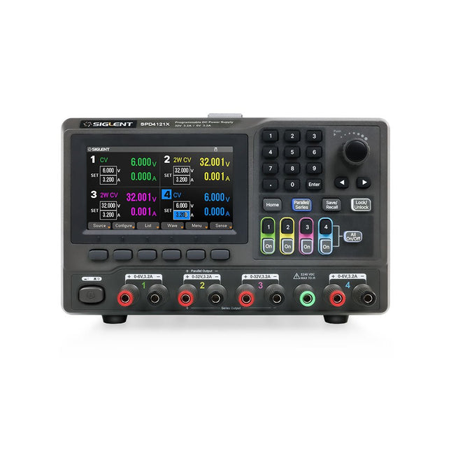
Siglent Siglent SPD4121X 4-Kanal Netzteil (285 W)
The Siglent SPD4121X is a 4-channel DC Linear Programmable Power Supply equipped with a 4.3-inch TFT-LCD display, friendly human-machine interface, and excellent performance indicators. Real-time waveform display provides engineers with an informative user interface. SPD4121X offers a total output power of 285 W with a resolution of 1 mV/1 mA. The maximum voltage and current for each channel are as follows: CH1: 15 V/1.5 A CH2: 12 V/10 A CH3: 12 V/10 A CH4: 15 V/1.5 A Features Rated output power: 285 W Rated voltage: 32 V, 12 V, 30 V Up to four high-precision power supplies with independent controllable outputs, supporting CH2 and CH3 series and parallel connections Clear graphical interface with waveform and timer display modes 5-digit voltage and current display with minimum resolution of 1 mV, 1 mA Fast output response time: <50us The high current channel support remote voltage compensation sense function. The maximum compensation voltage is 0.6 V Overvoltage protection and overcurrent protection or safe and accurate operation Equipped with a 4.3-inch TFT-LCD display (480 x 272 resolution) USB and LAN standard communication USB-GPIB module is optional Excellent channel density with up to 4 channels in a 3U half rack package Internal data storage for setups and parameters Embedded Web Server with instrument communication that doesn’t require software installation Fully SCPI programming command set support as well as a LabView driver for remote control and system automation Technische Daten SPD4323X SPD4121X SPD4306X Channel Output CH1: Voltage 0 to 6 V Current 0 to 3.2 ACH2: Voltage 0 to 32 V Current 0 to 3.2 ACH3: Voltage 0 to 32 V Current 0 to 3.2 ACH4: Voltage 0 to 6 V Current 0 to 3.2 A CH1: Voltage 0 to 15 V Current 0 to 1.5 ACH2: Voltage 0 to 12 V Current 0 to 10 ACH3: Voltage 0 to 12 V Current 0 to 10 ACH4: Voltage 0 to 15 V Current 0 to 1.5 A CH1: Voltage 0 to 15 V Current 0 to 1.5 ACH2: Voltage 0 to 30 V Current 0 to 6 ACH3: Voltage 0 to 30 V Current 0 to 6 ACH4: Voltage 0 to 15 V Current 0 to 1 A Resolution 1 mV, 1 mA 1 mV, 1 mA 1 mV, 1 mA Setting Accuracy Voltage: ±(0.03% of reading+10) mV, Current: ±(0.3% of reading+10) mA Voltage: ±(0.03% of reading+10) mV, Current: ±(0.3% of reading+10) mA Voltage: ±(0.03% of reading+10) mV, Current: ±(0.3% of reading+10) mA Readback Accuracy Voltage: ±(0.03% of reading+10) mV, Current: ±(0.3% of reading+10) mA Voltage: ±(0.03% of reading+10) mV, Current: ±(0.3% of reading+10) mA Voltage: ±(0.03% of reading+10) mV, Current: ±(0.3% of reading+10) mA Display 4.3" TFT-LCD 5-digit voltage and current display 4.3" TFT-LCD 5-digit voltage and current display 4.3" TFT-LCD 5-digit voltage and current display Output power 240 W 285 W 400 W Lieferumfang 1x Siglent SPD4121X Power Supply 1x Power cord (EU) 1x Output test cord (3 A) 1x USB cable 1x Quick start guide Downloads Datasheet Manual Quick start
€ 871,20
Bestpreis
-
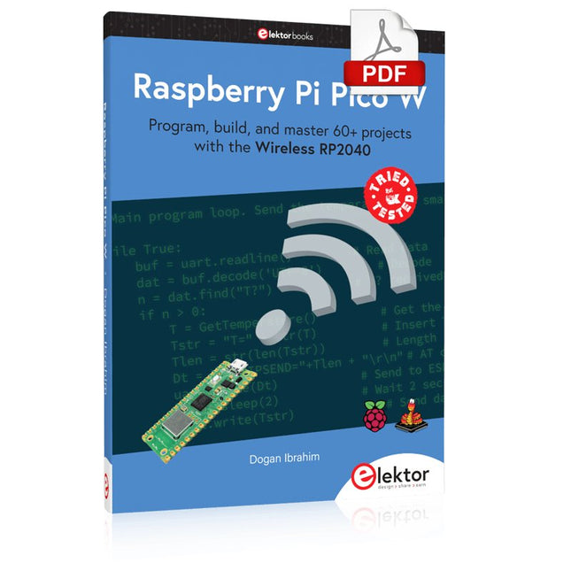
Elektor Digital Raspberry Pi Pico W (E-book)
Program, build, and master 60+ projects with the Wireless RP2040 The Raspberry Pi Pico and Pico W are based on the fast, efficient, and low-cost dual-core ARM Cortex M0+ RP2040 microcontroller chip running at up to 133 MHz and sporting 264 KB of SRAM and 2 MB of Flash memory. Besides spacious memory, the Pico and Pico W offer many GPIO pins, and popular peripheral interface modules like ADC, SPI, I²C, UART, PWM, timing modules, a hardware debug interface, and an internal temperature sensor. The Raspberry Pi Pico W additionally includes an on-board Infineon CYW43439 Bluetooth and Wi-Fi chipset. At the time of writing this book, the Bluetooth firmware was not yet available. Wi-Fi is however fully supported at 2.4 GHz using the 802.11b/g/n protocols. This book is an introduction to using the Raspberry Pi Pico W in conjunction with the MicroPython programming language. The Thonny development environment (IDE) is used in all of the 60+ working and tested projects covering the following topics: Installing the MicroPython on Raspberry Pi Pico using a Raspberry Pi or a PC Timer interrupts and external interrupts Analogue-to-digital converter (ADC) projects Using the internal temperature sensor and external sensor chips Using the internal temperature sensor and external temperature sensor chips Datalogging projects PWM, UART, I²C, and SPI projects Using Bluetooth, WiFi, and apps to communicate with smartphones Digital-to-analogue converter (DAC) projects All projects are tried & tested. They can be implemented on both the Raspberry Pi Pico and Raspberry Pi Pico W, although the Wi-Fi-based subjects will run on the Pico W only. Basic programming and electronics experience are required to follow the projects. Brief descriptions, block diagrams, detailed circuit diagrams, and full MicroPython program listings are given for all projects.
€ 34,95
Mitglieder: € 31,46
-

Elektor Digital Elektor Juli/Augustus 2023 PDF (NL)
Elektor GREEN en GOLD leden kunnen deze uitgave hier downloaden.Nog geen lid? Klik hier om een lidmaatschap af te sluiten. Kiesschijftelefoon als afstandsbedieningvoor licht kies 1; voor koffie kies 2 GPS-gebaseerde snelheidsmeternooit meer bekeuringen RGB-stroboscoop met Arduinokleurige toepassing van een nuttig instrument Draadloze nooddrukknopmeer veiligheid met LoRa Alle begin......volgt de emitter Vrij te kiezen onafhankelijke hystereseniveaus voor comparatorenmet simulaties, spreadsheets en algebra Impedantie-analyzer op basis van een ESP32simpel, weinig onderdelen en goedkoop! Oost West Lab Bestzelfbouw moet gestimuleerd! Het MCCAB Arduino Nano Training Boardalle hardware voor de “Microcontrollers Hands-On Course” Uit het leven gegrepenmodern luddisme Sensor-ABC: de DS18B20 temperatuursensoraansluiting op de 1-Wire bus Gaan Matter en Thread het Smart Home redden?nieuwe standaarden om het slimme huis te vereenvoudigen Een kwestie van samenwerkingontwikkelen met het Thing Plus Matter Board en Simplicity Studio Elektor IIIIinfographicIoT en sensoren Matter, ExpressLink, Rainmaker – waar hebben we het over?vraaggesprek met Amey Inamdar van Espressif De juiste keuze van microcontroller-ontwikkelkitsvoor IoT- en IIoT-toepassingen Condensatoren gedragen zich niet altijd capacitief! Een NTP-klok met CircuitPythonwaarom zou je deze programmeertaal gebruiken? Bouw een cool IoT-display'met de Phambili Newt De doppler-bewegingssensor HB100theorie en praktijk Een gids voor puristisch programmeren (deel 1)voor STM32 en andere controllers Siglent SDM3045X-multimeter Microprocessoren voor embedded systemenvreemde onderdelen Microcontroller-documentatie verklaarddeel 3: blokschema’s en meer Low-power LoRa-weerstationbouw zelf een weerstation met een groot bereik Transverter voor de 70cm-band Klimaat aan ingenieurssnelheid is geboden! Hexadoku
€ 9,95
-

Elektor Digital Mastering the I²C Bus (E-book)
Mastering the I²C Bus takes you on an exploratory journey of the I²C Bus and its applications. Besides the Bus protocol, plenty of attention is given to the practical applications and designing a stable system. The most common I²C compatible chip classes are covered in detail. Two experimentation boards are available that allow for rapid prototype development. These boards are completed by a USB to I²C probe and a software framework to control I²C devices from your computer. All samples programs can be downloaded from the 'Attachments/Downloads' section on this page. Projects built on Board 1: USB to I²C Interface, PCA 9534 Protected Input, PCA 9534 Protected Output, PCA 9553 PWM LED Controller, 24xxx EEPROM Module, LM75 Temperature Sensor, PCA8563 Real-time Clock with Battery Backup, LCD and Keyboard Module, Bus Power Supply. Projects built on Board 2: Protected Input, Protected Output, LM75 Temperature Sensor, PCF8574 I/O Board, SAA1064 LED Display, PCA9544 Bus Expander, MCP40D17 Potentiometer, PCF8591 AD/DA, ADC121 A/D Converter, MCP4725 D/A Converter, 24xxx EEPROM Module.
€ 34,95
Mitglieder: € 31,46
-

Peak Peak Atlas Pro Pack (LCR45 und DCA75)
Dieses Paket enthält den LCR45, perfekt für erfahrene Bastler und Experten. Es beinhaltet außerdem das sehr populäre DCA Pro (model DCA75), fantastisch für die Identifikation von Komponenten. Kompletiert wird das Paket durch ein USB-Kabel und einem USB-Stick mit der nötigen Software. DCA75 Der DCA75 unterstützt alle Komponenten die von PEAK Atlas DCA55 unterstützt werden und beinhaltet sogar noch weitere: Transistoren (BJT’s mit Darlingtons und “digitale” Transistoren), Silikon und Germanuim Typen. Misst den Verstärkungsfaktor, VBE, Ableitstrom und die Sättigungsspannung. Unijunctiontransistoren (UJT’s) werden nicht unterstützt. MOSFET‘s, Anreicherungstyp und Abreicherungstyp. Misst mit einem Ansprechwert (von ID=5 mA), einer geschätzten Transkonduktanz (in einer Spanne von 3 mA - 5 mA) und RDS(on) mit einer Auflösung von 1 Ω. JFETs, mit SiC-Typen. Misst mit pinch-off Spannung (ID=5μA), geschätzter Transkonduktanz (in einer Spanne von 3 mA – 5 mA) und RDS(on) bei einer Auflösung von 1 Ω. IGBTs (Biopolartransistor). Misst mit einem Ansprechwert (IC=5mA), geschätzter Transkonduktanz (in einer Spanne von 3 mA – 5 mA) und Sättigungsspannung. Dioden und Diodennetzwerke. Misst eine Durchlassspannung bei 5 mA. LED’s und zweifarbige LED’s (2 Leiter und 3 Leiter Typ). Misst Durchlassspannung von jedem LED-Element bei 5 mA. Zener Dioden mit einer gemessenen Zener Spannung bis zu 9 V bei 5 mA. Spannungsregulatoren (misst Spannungsregulierung von < 8 V, Abfallspannung, Ruhestrom). Triac’s und Thyristoren welche weniger als 10 mA von Steuerstrom und Haltestrom benötigen. Unabhängig oder mit PC funktionstüchtig Das ATLAS DCA75 PRO kann eigenständig arbeiten oder mit einem PC verbunden werden. Wie auch immer, das DCA Pro wird automatisch die Komponente und die Kontaktbelegung identifizieren. Außerdem misst es eine Reihe von Komponenteneigenschaften, wie den Transistorfaktor, Ableitungen, MOSFET und IGBT-Spannung. Curve Tracing Wenn das ATLAS DCA75 PRO mit einem PC mit dem beiliegenden USB-Kabel verbunden wird, hat man einen Überblick über eine Reihe von Schwachspannungskurven. Verschiedene Graphen sind nutzbar, weitere folgen: Bipolartransistor Ausgabekennlinie, IC vs VCE Bipolartransistor Verstärkungsfaktoren, hFE vs VCE Bipolartransistor Verstärkungsfaktoren, hFE vs IC MOSFET und IGBT Ausgabefunktion, ID vs VDS MOSFET und IGBT Transferfunktion, ID vs VGS JFET Ausgabefunktion, ID vs VDS JFET Transferfunktion, ID vs VGS Spannungsregulator, VOUT vs VIN Spannungsregulator, IQ vs VIN PN Anschluss I/V Kurven, vorwärts und rückwärts Optionen (für Zener Dioden). Beim Curve tracing werden Testparameter von +/- 12 V, +/- 12 mA eingestellt. Sämtliche curve-tracing Daten können direct in Excel© für weitere Grafikanalysen eingespeist werden. Die Software ist für die Betriebssysteme Windows XP, Vista, 7, 8 and 10 gemacht. LCR45 Ein großartiger LCR Analysator, welcher die passiven Komponenten (Spulen, Kondensatoren und Widerstände) messen kann.Das LCR45 bietet eine erhöhte Messauflösung (besser aks 0.1 uH!). Des Weiteren kann die Test-Frequenz DC manuel oder automatisch auf, 1 kHz, 15 kHz und 200 kHz verändert werden. Nicht hergestellt für schaltungsinterne Messungen. Automatische oder manuelle Komponenten Slektion: Spule, Kondensator oder Widerstand Automatische oder manuelle Test-Frequenz- Selektion: DC, 1 kHz, 15 kHz und 200 kHz Induktivitäten von 0.1 uH bis 10 H Kapazitäten von 0.1 pF bis 10,000 uF Widerstände von 0.1 Ohm bis 2 MOhm Induktivitäten Messung zeigt auch die Spulenwiderstände Zeigt "Component type and values", "Complex Impedance", "Magnitude/Phase" und "Admittance" Test-Frequenz wird für alle Messungen angezeigt Abweichung von 1,5% für Spulen und Kondensatoren (siehe Tabelle für weiterer Details) Abweichung von 1% für Widerständen Tastkopf wird mit 2 mm vergoldeten Steckern und Buchsen komplettiert Vergoldete Prüfspitzen sind austauschbar Lieferumfang LCR45 DCA75 Extra GP23 Batterie Extra AAA Zelle Dual Carry Gehäuse
€ 320,11
-

Weller Weller WE1010 Digitale Lötstation (70 W)
High-quality soldering station with the most important tools and consumables, ideal for universal soldering applications. Features 1-Channel Power Unit, digital, 70 W Power unit, 1 channel with soldering iron WEP 70 and safety rest PH 70 70W solder iron with ergonomic handle and providing toolless tip change ESD safe station, iron and heat-resistant silicon cable for safe handling Using ET soldering tips Standby mode and auto setback conserves energy, protects equipment Password-protected to preserve settings Specifications Dimensions: 150 x 120 x 98 mm Weight: 1.4 kg Display: Digital LC Display Temperature range: Adjustable from 100°C - 450°C (200°F - 850°F) Voltage: 230 V Channels: 1 Temperature range (depends on tool) °C: 100-450 Temperature range (depends on tool) °F: 200-850 Temperature accuracy °C: Average tip temperature can be „offset“ to +/- 5°C at idle with no load Temperature accuracy °F: Average tip temperature can be „offset“ to +/- 9°F at idle with no load Temperature stability °C: ±6 Temperature stability °F: ±10 Heat-up time (ca) in seconds (50-350°C / 120-660°F): 28 sec. Heating output: 85 W
€ 155,00
-

Elektor Digital Elektor Special: Introduction to Electronics with Arduino (PDF)
Although the Arduino isn’t a novelty any longer, there are still many beginners who want to try programming and development with a microcontroller, and to them, it is all new. All beginnings can be difficult, though they should be light and enjoyable. You do not need much or expensive equipment for the examples. The circuits are built on a small breadboard, and, if necessary, connected to an Arduino Uno, which you can program on a Windows PC. You will find clear examples of how to build all circuits, ensuring easy and error-free reproduction. Projects Discussed Current & Voltage – How it all began Arduino Hardware Arduino Programming The Electrical Circuit Measuring with the Multimeter Circuit Diagrams and Breadboards Creating Circuit Diagrams Breadboard Views with Fritzing Online Circuit Simulation Indispensable: Resistors (Part 1) Hands-on with Resistors (Part 2) Variable Resistors Diodes: One-way Street for Current The Transistor Switch Electromagnetism Relays and Motors op-amps: Operational Amplifiers Capacitors The NE555 Timer PWM and Analogue Values with Arduino 7-Segment Temperature Display Introduction to Soldering and LCDs
€ 11,95
Mitglieder: € 10,76
-

Elektor Labs Elektor Laserkopf-Upgrade für Sanduhr
Der Elektor Laserkop verwandelt die Elektor Sanduhr in eine Uhr, die die Zeit auf eine im Dunkeln leuchtende Folie statt auf Sand schreibt. Neben der Anzeige der Zeit können damit auch flüchtige Zeichnungen erstellt werden. Der 5-mW-Laserpointer mit einer Wellenlänge von 405 nm erzeugt leuchtend grüne Zeichnungen auf der im Dunkeln leuchtenden Folie. Um optimale Ergebnisse zu erzielen, verwenden Sie das Kit in einem schwach beleuchteten Raum. Achtung: Schauen Sie niemals direkt in den Laserstrahl! Der Bausatz enthält alle notwendigen Komponenten, es ist jedoch das Anlöten von drei Drähten erforderlich. Hinweis: Dieses Kit ist auch mit der originalen Arduino-basierten Sanduhr aus dem Jahr 2017 kompatibel. Weitere Einzelheiten finden Sie unter Elektor 1-2/2017 und Elektor 1-2/2018.
€ 34,95
Mitglieder: € 31,46
-

Elektor Academy Pro Arduino (Programmierkurs)
Dieser komplette Mikrocontroller-Programmierkurs auf Basis des Arduino Uno umfasst ein Lehrbuch, ein Komponenten-Kit, praxisnahe Projekte sowie einen umfassenden Online-Kurs mit Simulationen. Er eignet sich ideal für das schrittweise Erlernen der Embedded-Programmierung mit Arduino anhand eines praktischen, hands-on Ansatzes. Eine praxisnahe Einführung in Embedded Systems mit dem Arduino Uno Dieser Kurs richtet sich an Personen ohne Vorkenntnisse im Bereich Embedded Systems, die einen strukturierten und beispielbasierten Einstieg suchen. Ein Kit bestehend aus LEDs und Widerständen, Schaltern, Sensoren und Aktoren, Displays, einem Breadboard und Kabeln sowie weiteren Komponenten ist enthalten. Diese werden im Kurs verwendet, um Beispielanwendungen zu veranschaulichen. Vorkenntnisse mit Arduino oder Embedded-Entwicklung sind nicht erforderlich. Jeder Abschnitt enthält praktische Beispiele und Mini-Projekte, die wichtige Konzepte festigen und zur weiteren Vertiefung anregen. Am Ende des Kurses werden Sie nicht nur in der Lage sein, die Beispiele nachzuvollziehen, sondern auch eigene Ideen und Anwendungen umzusetzen. Was werden Sie lernen? Mikrocontroller-Programmierung mit Arduino unter Verwendung des Uno R3 Boards Arbeiten mit digitalen Ein- und Ausgängen, Auslesen von Tastern und Encodern, Steuern von LEDs und Relais Auslesen analoger Eingänge, Spannungen und analoger Sensoren Erzeugung analoger Ausgangssignale und PWM Verwendung serieller Kommunikation wie UART, I²C und SPI zur Steuerung von Displays und zum Auslesen digitaler Sensoren und SD-Karten Zeitmanagement Arbeiten mit Interrupts Echtzeit-Sensordatenerfassung und Steuerung über Taster, LEDs und Displays Steuerung von Aktoren wie Relais und Servomotoren Für wen ist dieser Kurs geeignet? Studierende und Selbstlerner im Bereich Embedded Systems Makers und IoT-Enthusiasten, die ihre Hardware-Kenntnisse verbessern möchten Lehrkräfte und Trainer, die sofort einsetzbares Unterrichtsmaterial suchen Was ist im Lieferumfang enthalten? Zugang zum vollständigen Kurs auf der Elektor Academy Pro-Lernplattform Uno R3 Mikrocontroller-Board (+ USB-Kabel) Buch: Programming Microcontrollers in C/C++ Using Arduino Downloadbare Projektdateien für jedes Modul Komponenten-Set: 2× LED, rot, 5 mm LED, grün, 5 mm 3× Widerstand, 470 Ω, 0,25 W LDR Potentiometer, 10 kΩ, linear Taster Drehencoder-Modul Relaismodul DHT22 Feuchtigkeits- und Temperatursensor TM1637-kompatibles 4-stelliges 7-Segment-Display MPU-6050 IMU mit Stiftleisten SSD1306-kompatibles I²C OLED-Display Micro-SD-Kartenadapter mit Stiftleiste Buzzer SG90 Mikro-Servo ILI9341-kompatibles SPI 240×320 TFT-Display 20× Jumperkabel Breadboard Alle Programmierkurse (und Unterschiede im Inhalt) Kurs Arduino Raspberry Pi Pico with Arduino C/C++ ESP32 with Arduino C/C++ Raspberry Pi Pico with MicroPython ESP32 with MicroPython Online-Kurs Access to Arduino Course Access to Pico with Arduino C/C++ Course Access to ESP32 with Arduino C/C++ Course Access to Pico with MicroPython Course Access to ESP32 with MicroPython Course Board Uno R3 Raspberry Pi Pico ESP32 Raspberry Pi Pico ESP32 Buch Programming Microcontrollers in C/C++ Using Arduino Programming Microcontrollers in C/C++ Using Arduino Programming Microcontrollers in C/C++ Using Arduino Programming Microcontrollers in MicroPython Programming Microcontrollers in MicroPython Kit 40-teiliges Komponenten-Set 40-teiliges Komponenten-Set 40-teiliges Komponenten-Set 40-teiliges Komponenten-Set 40-teiliges Komponenten-Set
€ 69,95
Mitglieder: € 62,96
-

Elektor Digital Embedded in Embedded (E-book)
ARM Cortex-M Embedded Design from 0 to 1 Hobbyists can mash together amazing functional systems using platforms like Arduino or Raspberry Pi, but it is imperative that engineers and product designers understand the foundational knowledge of embedded design. There are very few resources available that describe the thinking, strategies, and processes to take an idea through hardware design and low-level driver development, and successfully build a complete embedded system. Many engineers end up learning the hard way, or never really learn at all. ARM processors are essentially ubiquitous in embedded systems. Design engineers building novel devices must understand the fundamentals of these systems and be able to break down large, complicated ideas into manageable pieces. Successful product development means traversing a huge amount of documentation to understand how to accomplish what you need, then put everything together to create a robust system that will reliably operate and be maintainable for years to come. This book is a case study in embedded design including discussion of the hardware, processor initialization, low‑level driver development, and application interface design for a product. Though we describe this through a specific application of a Cortex-M3 development board, our mission is to help the reader build foundational skills critical to being an excellent product developer. The completed development board is available to maximize the impact of this book, and the working platform that you create can then be used as a base for further development and learning. The Embedded in Embedded program is about teaching fundamental skill sets to help engineers build a solid foundation of knowledge that can be applied in any design environment. With nearly 20 years of experience in the industry, the author communicates the critical skill development that is demanded by companies and essential to successful design. This book is as much about building a great design process, critical thinking, and even social considerations important to developers as it is about technical hardware and firmware design. Downloads EiE Software Archive (200 MB) IAR ARM 8.10.1 (Recommended IDE version to use) (1.2 GB) IAR ARM 7.20.1 (Optional IDE version to use) (600 MB)
€ 44,95
Mitglieder: € 40,46
-
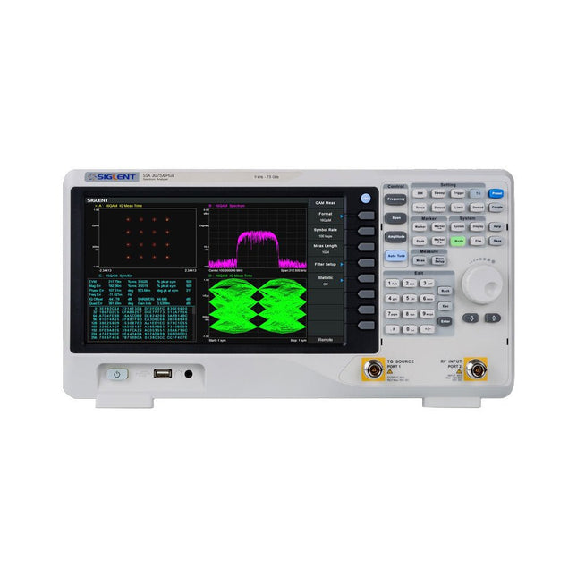
Siglent Siglent SSA3075X Plus Spektrum-Analyzer (9 kHz - 7,5 GHz)
Der Siglent SSA3075X Plus Spektrum-Analyzer ist ein leistungsstarkes und flexibles Werkzeug für die HF-Signal- und Netzwerkanalyse. Mit einem Frequenzbereich von 7,5 GHz bietet der Analysator zuverlässige automatische Messungen und mehrere Betriebsarten: Spektrum-Analyzer als Basis, optionale Funktionen umfassen HF-Leistungsmessung, Vektorsignal-Modulationsanalyse, Reflexionsmessung und EMI-Test. Zu den Anwendungsbereichen gehören die Überwachung/Bewertung von Sendungen, Standortvermessung, S-Parameter-Messung, analoge/digitale Modulationsanalyse, EMI-Vorprüfung, Forschung und Entwicklung, Ausbildung, Produktion und Wartung. Features Frequenzbereich des Spektrum-Analyzer von 9 kHz bis 7,5 GHz –165 dBm/Hz Angezeigter durchschnittlicher Geräuschpegel (typisch) –98 dBc/Hz. @ 10 kHz Offset-Phasenrauschen (1 GHz, typ.) Pegelmessunsicherheit <0,7 dB (typ.) 1 Hz Mindestauflösungsbandbreite (RBW) Vorverstärker (Std.) Tracking Generator (kostenlos inkl.) Analysemodus für analoge und digitale Signalmodulation (opt.) Reflexionsmesskit (opt.) EMI-Filter und Quasi-Peak-Detektor-Kit (opt.) Erweitertes Messkit (opt.) 10,1-Zoll-Multi-Touch-Bildschirm, Maus und Tastatur werden unterstützt Webbrowser-Fernsteuerung auf PCs und mobilen Endgeräten sowie Dateibetrieb Technische Daten SSA3015X Plus SSA3021X Plus SSA3032X Plus SSA3075X Plus Frequenzbereich 9 kHz ~ 1,5 GHz 9 kHz ~ 2,1 GHz 9 kHz ~ 3,2 GHz 9 kHz ~ 7,5 GHz Auflösung Bandbreite 1 Hz ~ 1 MHz 1 Hz ~ 1 MHz 1 Hz ~ 1 MHz 1 Hz ~ 3 MHz Phasenrauschen <–99 dBc/Hz <–98 dBc/Hz <–98 dBc/Hz <–98 dBc/Hz Genauigkeit der Gesamtamplitude <1,2 dB <0,7 dB <0,7 dB <0,7 dB Anzeige des durchschnittlichen Geräuschpegels –156 dBm/Hz –161 dBm/Hz –161 dBm/Hz –165 dBm/Hz Lieferumfang Siglent SSA3075X Plus Spektrum-Analyzer USB-Kabel Netzkabel Kurzanleitung Downloads Datasheet Manual Documentation Firmware
€ 7.875,89
Bestpreis


