Das SparkFun RedBoard Qwiic ist eine Arduino-kompatible Platine, die Funktionen verschiedener Arduinos mit dem Qwiic Connect System kombiniert.
Merkmale
ATmega328-Mikrocontroller mit Optiboot-Bootloader
Kompatibel mit R3 Shield
CH340C Seriell-USB-Konverter
Spannungspegel-Jumper von 3,3 V bis 5 V
A4 / A5 Brücken
Spannungsregler AP2112
ISP-Header
Eingangsspannung: 7 V - 15 V
1 Qwiic-Anschluss
16 MHz Taktfrequenz
32 k Flash-Speicher
Komplette SMD-Konstruktion
Verbesserter Reset-Knopf
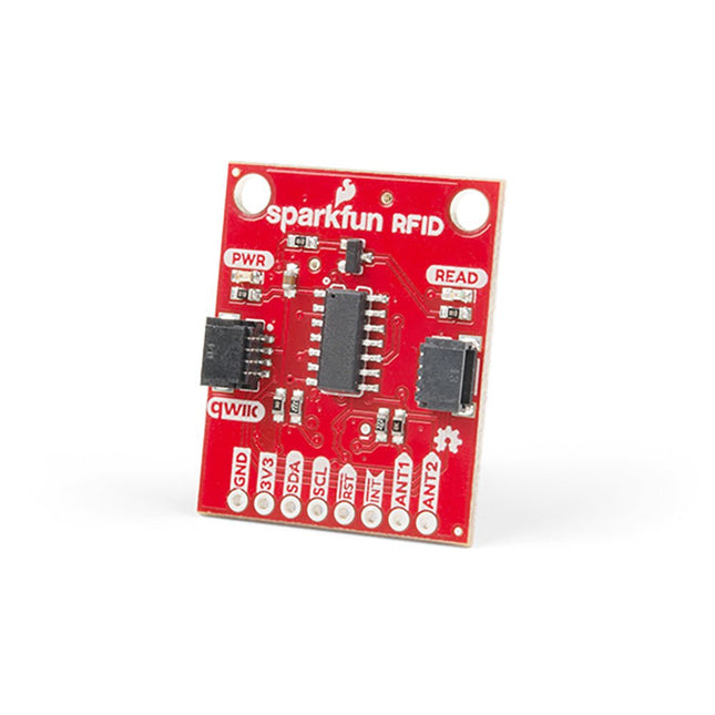
Stecken Sie ein Lesegerät in die Header, verwenden Sie ein Qwiic-Kabel, scannen Sie Ihren 125kHz-ID-Tag, und die eindeutige 32-Bit-ID wird auf dem Bildschirm angezeigt. Das Gerät kommt mit einer Lese-LED und einem Summer, aber keine Sorge, es gibt einen Jumper, den Sie schneiden können, um den Summer zu deaktivieren, wenn Sie wollen. Durch die Verwendung von SparkFuns praktischem Qwiic-System ist kein Löten erforderlich, um das Gerät mit dem Rest Ihres Systems zu verbinden. Dennoch haben wir die Pins im 0,1"-Abstand herausgebrochen, falls Sie lieber ein Breadboard verwenden möchten.
Der Qwiic RFID nutzt den integrierten ATtiny84A, um die sechs Byte lange ID Ihrer 125kHz-RFID-Karte zu erfassen, mit einem Zeitstempel zu versehen und auf einen Stapel zu legen, der bis zu 20 eindeutige RFID-Scans auf einmal speichert. Diese Informationen sind mit einigen einfachen I2C-Befehlen leicht abrufbar.
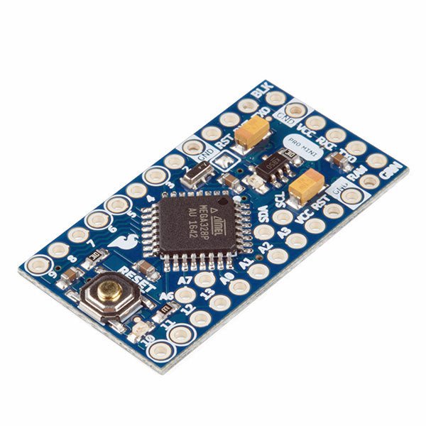
Der Arduino Pro Mini ist ein Mikrocontroller-Board auf Basis des ATmega328P.
Es hat 14 digitale Eingangs-/Ausgangs-Pins (von denen 6 als PWM-Ausgänge verwendet werden können), 6 analoge Eingänge, einen On-Board-Resonator, eine Reset-Taste und Löcher für die Montage von Stiftleisten. Eine sechspolige Stiftleiste kann mit einem FTDI-Kabel oder einem SparkFun-Breakout-Board verbunden werden, um die Platine über USB mit Strom zu versorgen und mit ihr zu kommunizieren.
Der Arduino Pro Mini ist für die semi-permanente Installation in Objekten oder Ausstellungen gedacht. Die Platine wird ohne vormontierte Stiftleisten geliefert, was die Verwendung verschiedener Arten von Steckern oder das direkte Anlöten von Drähten ermöglicht. Das Pin-Layout ist mit dem Arduino Mini kompatibel.
Technische Daten
Microcontroller
ATmega328P
Board Stromversorgung
5-12 V
Schaltung Betriebsspannung
5 V
Digitale E/A-Pins
14
PWM Pins
6
UART
1
SPI
1
I²C
1
Analogeingangs-Pins
6
Externe Interrupts
2
DC-Strom pro I/O-Pin
40 mA
Flash Memory
32 KB, davon 2 KB vom Bootloader verwendet
SRAM
2 KB
EEPROM
1 KB
Taktgeschwindigkeit
16 MHz
Abmessungen
18 x 33.3 mm
Downloads
Eagle files
Schematics
Maker Line ist ein Zeilensensor mit einem Array aus 5 IR-Sensoren, der Linien mit einer Breite von 13 mm bis 30 mm verfolgen kann.
Auch die Sensorkalibrierung wird vereinfacht. Es ist nicht mehr nötig, das Potentiometer für jeden einzelnen IR-Sensor einzustellen. Sie müssen nur die Kalibrierungstaste 2 Sekunden lang drücken, um in den Kalibrierungsmodus zu wechseln. Anschließend müssen Sie das Sensorarray über die Linie bewegen, die Taste erneut drücken und schon kann es losgehen.
Die Kalibrierungsdaten werden im EEPROM gespeichert und bleiben auch nach dem Ausschalten des Sensors erhalten. Die Kalibrierung muss daher nur einmal durchgeführt werden, es sei denn, die Sensorhöhe, Linienfarbe oder Hintergrundfarbe hat sich geändert.
Maker Line unterstützt auch zwei Ausgänge: 5 x digitale Ausgänge für den Zustand jedes Sensors unabhängig voneinander, was einem herkömmlichen IR-Sensor ähnelt, aber Sie profitieren von der einfachen Kalibrierung, und auch ein analoger Ausgang, dessen Spannung die Linienposition darstellt. Der analoge Ausgang bietet auch eine höhere Auflösung im Vergleich zu einzelnen digitalen Ausgängen. Dies ist besonders nützlich, wenn beim Bau eines Linienverfolgungsroboters mit PID-Steuerung eine hohe Genauigkeit erforderlich ist.
Features
Betriebsspannung: DC 3,3 V und 5 V kompatibel (mit Verpolungsschutz)
Empfohlene Linienbreite: 13 mm bis 30 mm
Wählbare Linienfarbe (hell oder dunkel)
Erfassungsabstand (Höhe): 4 mm bis 40 mm (Vcc = 5 V, schwarze Linie auf weißer Oberfläche)
Sensor-Aktualisierungsrate: 200 Hz
Einfacher Kalibrierungsprozess
Duale Ausgabetypen: 5 x digitale Ausgänge repräsentieren jeden IR-Sensorstatus, 1 x analoger Ausgang repräsentiert die Zeilenposition.
Unterstützt eine breite Palette von Controllern wie Arduino, Raspberry Pi usw.
Downloads
Datenblatt
Tutorial: Einen kostengünstigen Linienverfolgungsroboter bauen
Principles, Systems, and Electronics
This handbook provides a detailed study of the sensors and actuators at the heart of modern vehicle electronics. It begins with basic electrical and electronic concepts, introducing the principles and terminology essential for understanding automotive systems.
The book explores sensors and actuators on a system-by-system basis, including:
Fundamentals of electrical engineering, electromagnetic phenomena, and motor principles
Passive and active electronic components, integrated circuits, protection devices, and automotive-grade electronics
Sensor characteristics, signal conditioning, ADCs, PWM and frequency outputs, and interface adaptation
Automotive communication links and protocols, including LIN and SENT
Engine sensors: air mass, pressure, temperature, speed, position, exhaust and emissions-related sensors
Transmission sensors for manual and automatic systems
Steering and suspension sensors for conventional and active systems
Vehicle body and electrical system sensors for comfort, climate, access, and monitoring functions
Engine actuators such as throttle bodies, injectors, turbo actuators, EGR systems, ignition components, and pumps
Transmission, brake, steering, suspension, and body actuators
Identification and coding of electronic components and packages commonly used in automotive applications
The structure and operating principles of each component are explained, with relevant electronic circuitry illustrated. Its system-oriented organization and practical focus make it a valuable reference for understanding, testing, and troubleshooting automotive electronic systems.
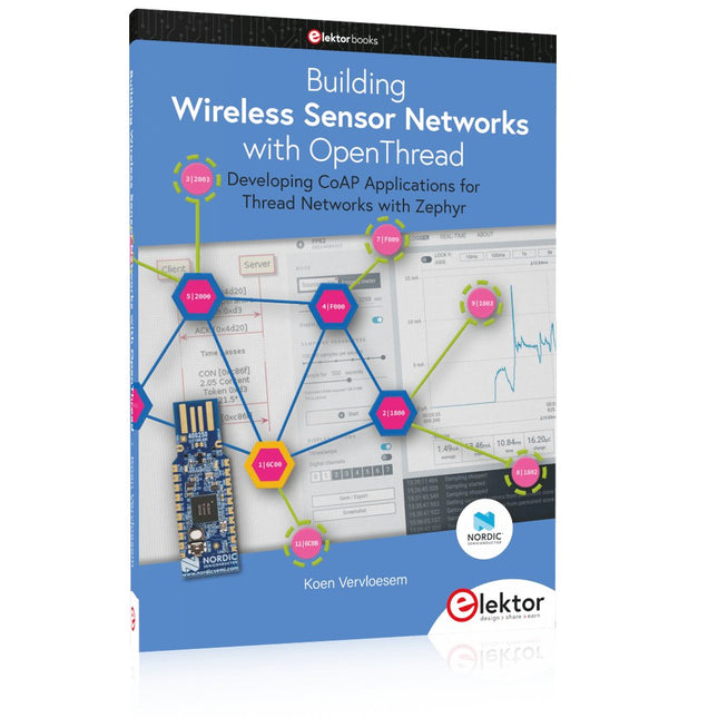
Developing CoAP applications for Thread networks with Zephyr
This book will guide you through the operation of Thread, the setup of a Thread network, and the creation of your own Zephyr-based OpenThread applications to use it. You’ll acquire knowledge on:
The capture of network packets on Thread networks using Wireshark and the nRF Sniffer for 802.15.4.
Network simulation with the OpenThread Network Simulator.
Connecting a Thread network to a non-Thread network using a Thread Border Router.
The basics of Thread networking, including device roles and types, as well as the diverse types of unicast and multicast IPv6 addresses used in a Thread network.
The mechanisms behind network discovery, DNS queries, NAT64, and multicast addresses.
The process of joining a Thread network using network commissioning.
CoAP servers and clients and their OpenThread API.
Service registration and discovery.
Securing CoAP messages with DTLS, using a pre-shared key or X.509 certificates.
Investigating and optimizing a Thread device’s power consumption.
Once you‘ve set up a Thread network with some devices and tried connecting and disconnecting them, you’ll have gained a good insight into the functionality of a Thread network, including its self-healing capabilities. After you’ve experimented with all code examples in this book, you’ll also have gained useful programming experience using the OpenThread API and CoAP.
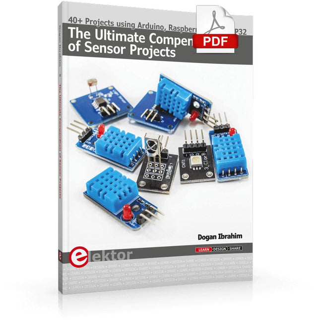
40+ Projects using Arduino, Raspberry Pi and ESP32
This book is about developing projects using the sensor-modules with Arduino Uno, Raspberry Pi and ESP32 microcontroller development systems. More than 40 different sensors types are used in various projects in the book. The book explains in simple terms and with tested and fully working example projects, how to use the sensors in your project. The projects provided in the book include the following:
Changing LED brightness
RGB LEDs
Creating rainbow colours
Magic wand
Silent door alarm
Dark sensor with relay
Secret key
Magic light cup
Decoding commercial IR handsets
Controlling TV channels with IT sensors
Target shooting detector
Shock time duration measurement
Ultrasonic reverse parking
Toggle lights by clapping hands
Playing melody
Measuring magnetic field strength
Joystick musical instrument
Line tracking
Displaying temperature
Temperature ON/OFF control
Mobile phone-based Wi-Fi projects
Mobile phone-based Bluetooth projects
Sending data to the Cloud
The projects have been organized with increasing levels of difficulty. Readers are encouraged to tackle the projects in the order given. A specially prepared sensor kit is available from Elektor. With the help of this hardware, it should be easy and fun to build the projects in this book.
Principles, Systems, and Electronics
This handbook provides a detailed study of the sensors and actuators at the heart of modern vehicle electronics. It begins with basic electrical and electronic concepts, introducing the principles and terminology essential for understanding automotive systems.
The book explores sensors and actuators on a system-by-system basis, including:
Fundamentals of electrical engineering, electromagnetic phenomena, and motor principles
Passive and active electronic components, integrated circuits, protection devices, and automotive-grade electronics
Sensor characteristics, signal conditioning, ADCs, PWM and frequency outputs, and interface adaptation
Automotive communication links and protocols, including LIN and SENT
Engine sensors: air mass, pressure, temperature, speed, position, exhaust and emissions-related sensors
Transmission sensors for manual and automatic systems
Steering and suspension sensors for conventional and active systems
Vehicle body and electrical system sensors for comfort, climate, access, and monitoring functions
Engine actuators such as throttle bodies, injectors, turbo actuators, EGR systems, ignition components, and pumps
Transmission, brake, steering, suspension, and body actuators
Identification and coding of electronic components and packages commonly used in automotive applications
The structure and operating principles of each component are explained, with relevant electronic circuitry illustrated. Its system-oriented organization and practical focus make it a valuable reference for understanding, testing, and troubleshooting automotive electronic systems.
,
von Saad Imtiaz
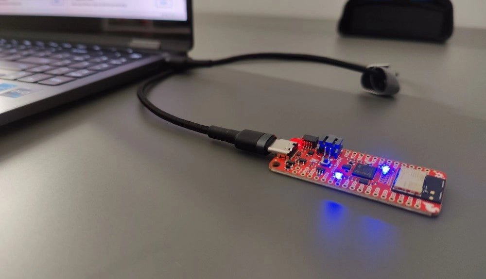
SparkFun Thing Plus Matter (MGM240P): Ein vielseitiges IoT-Entwicklungsboard basierend auf Matter (Testbericht)
Das SparkFun Thing Plus Matter - MGM240P ist ein vielseitiges und funktionsreiches Entwicklungsboard für die Erstellung von Matter-basierten IoT-Geräten. Matter, früher bekannt als Project CHIP...
,
von Clemens Valens
Review: Strahlungsdetektion mit dem Geigerzähler-Kit von MightyOhm
Der Geigerzähler von MightyOhm kann Beta- und Gammastrahlung erkennen. Da radioaktive Strahlung so gefährlich ist, sollten Sie Ihre Umgebung im Auge behalten und sich einen...
,
von Lobna Belarbi
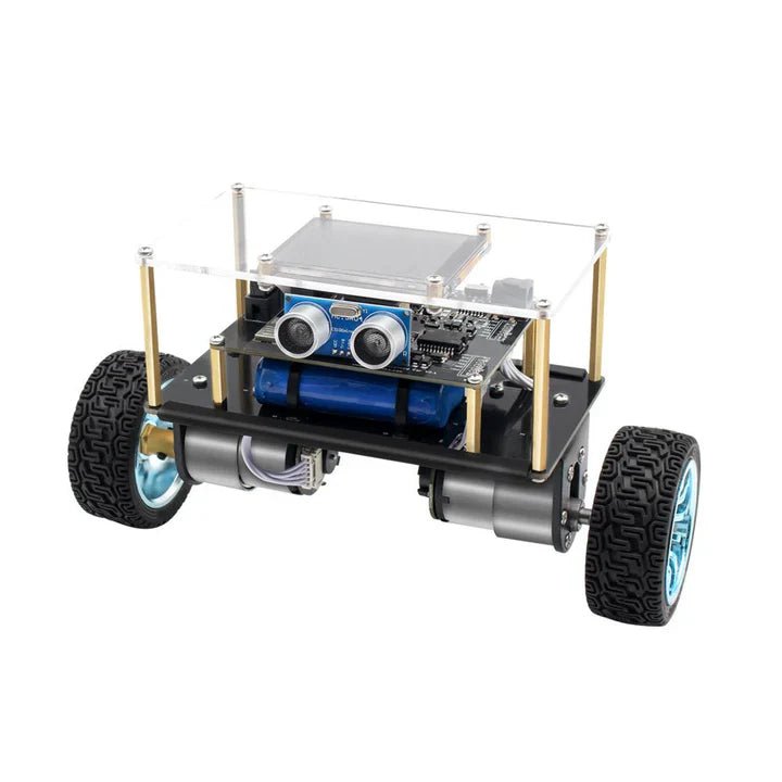
Affordable Robot Kits to Kickstart Your Robotics Journey
Robotics is an exciting and rewarding field, but getting started can be intimidating—especially when it comes to choosing the right kit. Fortunately, Elektor offers a...
,
von Lobna Belarbi
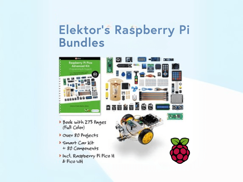
Elektors Raspberry Pi Bundles: Von Einsteiger-Sets bis zu fortgeschrittenen Kits
Finde das perfekte Raspberry Pi Bundle für dein Erfahrungsniveau Egal, ob du gerade erst in die Welt des Raspberry Pi eintauchst oder bereits anspruchsvolle Projekte...