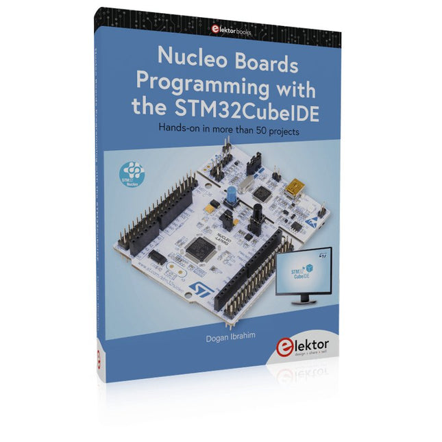
Hands-on in more than 50 projects
STM32 Nucleo family of processors are manufactured by STMicroelectronics. These are low-cost ARM microcontroller development boards. This book is about developing projects using the popular STM32CubeIDE software with the Nucleo-L476RG development board. In the early Chapters of the book the architecture of the Nucleo family is briefly described.
The book covers many projects using most features of the Nucleo-L476RG development board where the full software listings for the STM32CubeIDE are given for each project together with extensive descriptions. The projects range from simple flashing LEDs to more complex projects using modules, devices, and libraries such as GPIO, ADC, DAC, I²C, SPI, LCD, DMA, analogue inputs, power management, X-CUBE-MEMS1 library, DEBUGGING, and others. In addition, several projects are given using the popular Nucleo Expansion Boards. These Expansion Boards plug on top of the Nucleo development boards and provide sensors, relays, accelerometers, gyroscopes, Wi-Fi, and many others. Using an expansion board together with the X-CUBE-MEMS1 library simplifies the task of project development considerably.
All the projects in the book have been tested and are working. The following sub-headings are given for each project: Project Title, Description, Aim, Block Diagram, Circuit Diagram, and Program Listing for the STM32CubeIDE.
In this book you will learn about
STM32 microcontroller architecture;
the Nucleo-L476RG development board in projects using the STM32CubeIDE integrated software development tool;
external and internal interrupts and DMA;
DEBUG, a program developed using the STM32CubeIDE;
the MCU in Sleep, Stop, and in Standby modes;
Nucleo Expansion Boards with the Nucleo development boards.
What you need
a PC with Internet connection and a USB port;
STM32CubeIDE software (available at STMicroelectronics website free of charge)
the project source files, available from the book’s webpage hosted by Elektor;
Nucleo-L476RG development board;
simple electronic devices such as LEDs, temperature sensor, I²C and SPI chips, and a few more;
Nucleo Expansion Boards (optional).
The FRDM-MCXN947 is a compact and versatile development board designed for rapid prototyping with MCX N94 and N54 microcontrollers. It features industry-standard headers for easy access to the MCU's I/Os, integrated open-standard serial interfaces, external flash memory, and an onboard MCU-Link debugger.
Technische Daten
Microcontroller
MCX-N947 Dual Arm Cortex-M33 cores @ 150 MHz each with optimized performance efficiency, up to 2 MB dual-bank flash with optional full ECC RAM, External flash
Accelerators: Neural Processing Unit, PowerQuad, Smart DMA, etc.
Memory Expansion
*DNP Micro SD card socket
Connectivity
Ethernet Phy and connector
HS USB-C connectors
SPI/I²C/UART connector (PMOD/mikroBUS, DNP)
WiFi connector (PMOD/mikroBUS, DNP)
CAN-FD transceiver
Debug
On-board MCU-Link debugger with CMSIS-DAP
JTAG/SWD connector
Sensor
P3T1755 I³C/I²C Temp Sensor, Touch Pad
Expansion Options
Arduino Header (with FRDM expansion rows)
FRDM Header
FlexIO/LCD Header
SmartDMA/Camera Header
Pmod *DNP
mikroBUS
User Interface
RGB user LED, plus Reset, ISP, Wakeup buttons
Lieferumfang
1x FRDM-MCXN947 Development Board
1x USB-C Cable
1x Quick Start Guide
Downloads
Datasheet
Block diagram
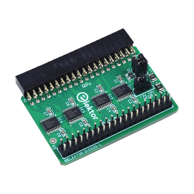
Wenn Sie regelmäßig mit dem Raspberry Pi experimentieren und eine Vielzahl von externer Hardware über die Stiftleiste an den GPIO-Port anschließen, haben Sie in der Vergangenheit vielleicht schon einige Schäden verursacht. Das Elektor Raspberry Pi Buffer Board ist dazu da, dies zu verhindern! Das Board ist kompatibel mit Raspberry Pi Zero, Zero 2 (W), 3, 4, 5, 400 und 500.
Alle 26 GPIOs sind mit bidirektionalen Spannungswandlern gepuffert, um den Raspberry Pi beim Experimentieren mit neuen Schaltungen zu schützen. Die Platine ist dafür vorgesehen, auf der Rückseite des Raspberry Pi 400/500 eingesetzt zu werden. Der Stecker zum Anschluss an den Raspberry Pi ist eine rechtwinklige 40-polige Buchse (2x20). Die Platine ist nur ein wenig breiter. An die Pufferausgangsbuchse kann ein 40-poliges Flachbandkabel mit entsprechenden 2x20-Steckern angeschlossen werden, um z. B. mit einer Schaltung auf einem Breadboard oder einer Platine zu experimentieren.
Die Schaltung verwendet 4x TXS0108E ICs von Texas Instruments. Die Platine lässt sich auch auf einem Raspberry Pi aufstellen.
Downloads
Schematics
Layout
STM32 Nucleo family of processors are manufactured by STMicroelectronics. These are low-cost ARM microcontroller development boards. This book is about developing projects using the popular Nucleo development board. In the early chapters of the book, the architecture of the Nucleo family is briefly described.
Software development tools that can be used with the Nucleo boards such as the Mbed, Keil MDK, TrueSTUDIO, and the System Workbench are described briefly in later Chapters.
The book covers many projects using most features of the STM32 Nucleo development boards where the full software listings for Mbed and System Workbench are given for every project. The projects range from simple flashing LEDs to more complex projects using modules and devices such as GPIO, ADC, DAC, I²C, LCD, analog inputs and others.
In addition, several projects are given using the Nucleo Expansion Boards, including popular expansion boards such as solid-state relay, MEMS and environmental sensors, DC motor driver, Wi-Fi, and stepper motor driver.
These Expansion Boards plug on top of the Nucleo development boards and simplify the task of project development considerably.
Features of this book
Learn the architecture of the STM32 microcontrollers
Learn how to use the Nucleo development board in projects using Mbed and System Workbench Toolchains
Learn how to use the Nucleo Expansion Boards with the Nucleo development boards
Update
The Mbed compiler has been replaced with two software packages: The Mbed Studio and Keil Studio Cloud. Both of these software packages are free of charge and are available on the Internet. If you need assistance using the Keil Studio Cloud, please download the Guide below.
Merkmale
Eingebaute USB-zu-Seriell-Schnittstelle
Eingebaute PCB-Antenne
Angetrieben durch Pineseed BL602 SoC mit Pinenut-Modell: 12S-Stempel
2 MB Flash
USB-C-Anschluss
Geeignet für Steckbrett-BIY-Projekte
An Bord befinden sich drei Farb-LEDs
Abmessungen: 25,4 x 44,0 mm
Hinweis: USB-Kabel ist nicht im Lieferumfang enthalten.
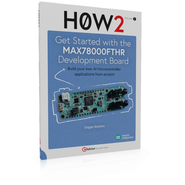
Build your own AI microcontroller applications from scratch
The MAX78000FTHR from Maxim Integrated is a small development board based on the MAX78000 MCU. The main usage of this board is in artificial intelligence applications (AI) which generally require large amounts of processing power and memory. It marries an Arm Cortex-M4 processor with a floating-point unit (FPU), convolutional neural network (CNN) accelerator, and RISC-V core into a single device. It is designed for ultra-low power consumption, making it ideal for many portable AI-based applications.
This book is project-based and aims to teach the basic features of the MAX78000FTHR. It demonstrates how it can be used in various classical and AI-based projects. Each project is described in detail and complete program listings are provided. Readers should be able to use the projects as they are, or modify them to suit their applications. This book covers the following features of the MAX78000FTHR microcontroller development board:
Onboard LEDs and buttons
External LEDs and buttons
Using analog-to-digital converters
I²C projects
SPI projects
UART projects
External interrupts and timer interrupts
Using the onboard microphone
Using the onboard camera
Convolutional Neural Network
Hands-on in more than 50 projects
STM32 Nucleo family of processors are manufactured by STMicroelectronics. These are low-cost ARM microcontroller development boards. This book is about developing projects using the popular STM32CubeIDE software with the Nucleo-L476RG development board. In the early Chapters of the book the architecture of the Nucleo family is briefly described.
The book covers many projects using most features of the Nucleo-L476RG development board where the full software listings for the STM32CubeIDE are given for each project together with extensive descriptions. The projects range from simple flashing LEDs to more complex projects using modules, devices, and libraries such as GPIO, ADC, DAC, I²C, SPI, LCD, DMA, analogue inputs, power management, X-CUBE-MEMS1 library, DEBUGGING, and others. In addition, several projects are given using the popular Nucleo Expansion Boards. These Expansion Boards plug on top of the Nucleo development boards and provide sensors, relays, accelerometers, gyroscopes, Wi-Fi, and many others. Using an expansion board together with the X-CUBE-MEMS1 library simplifies the task of project development considerably.
All the projects in the book have been tested and are working. The following sub-headings are given for each project: Project Title, Description, Aim, Block Diagram, Circuit Diagram, and Program Listing for the STM32CubeIDE.
In this book you will learn about
STM32 microcontroller architecture;
the Nucleo-L476RG development board in projects using the STM32CubeIDE integrated software development tool;
external and internal interrupts and DMA;
DEBUG, a program developed using the STM32CubeIDE;
the MCU in Sleep, Stop, and in Standby modes;
Nucleo Expansion Boards with the Nucleo development boards.
What you need
a PC with Internet connection and a USB port;
STM32CubeIDE software (available at STMicroelectronics website free of charge)
the project source files, available from the book’s webpage hosted by Elektor;
Nucleo-L476RG development board;
simple electronic devices such as LEDs, temperature sensor, I²C and SPI chips, and a few more;
Nucleo Expansion Boards (optional).
Das Elektor Arduino Nano MCCAB Trainingsboard enthält alle Bauteile (inkl. Arduino Nano), die für die Übungen des "Mikrocontroller-Praxiskurs für Arduino-Einsteiger" benötigt werden wie Leuchtdioden, Schalter, Taster, akustische Signalgeber usw. Auch externe Sensoren, Motoren oder Baugruppen können mit diesem Mikrocontroller-Übungssystem abgefragt oder gesteuert werden.
Technische Daten (Arduino Nano Trainingsboard MCCAB)
Stromversorgung
Über die USB-Verbindung des zur Erstellung der Programme sowieso angeschlossenen PCs oder ein externes Netzteil (nicht im Lieferumfang enthalten)
Betriebsspannung
+5 Vcc
Eingangsspannung
Alle Eingänge
0 V bis +5 V
VX1 und VX2
+8 V bis +12 V (nur bei Verwendung eines externen Netzteils)
Mikrocontrollermodul
Arduino Nano
Hardwareperipherie
LCD
2x16 Zeichen
Potenziometer P1 & P2
JP3: Auswahl der Betriebsspannung von P1 & P2
Verteiler
SV4: Verteiler für die BetriebsspannungenSV5, SV6: Verteiler für die Ein-/Ausgänge des Mikrocontrollers
Schalter und Taster
RESET-Taster auf dem Arduino Nano-Modul6x Tastschalter K1 … K66x Schiebeschalter S1 … S6JP2: Verbindung der Schalter mit den Eingängen des Mikrocontrollers
Summer
Piezo-Summer Buzzer1 mit Steckbrücke auf JP6
Leuchtanzeigen
LED L auf dem Arduino Nano-Modul, verbunden mit GPIO D1311x LED: Zustandsanzeige für die Ein-/AusgängeJP6: Verbindung der LEDs LD10 … LD20 mit den GPIOs D2 … D12
Serielle SchnittstellenSPI & I²C
JP4: Auswahl des Signals an Pin X der SPI-Steckerleiste SV12SV9 bis SV12: SPI-Interface (3,3 V/5 V) bzw. I²C-Interface
Schaltausgang für externe Geräte
SV1, SV7: Schaltausgang (maximal +24 V/160 mA, extern zugeführt)SV2: 2x13 Pins zum Anschluss externer Module
3x3 LED-Matrix (9 rote LEDs)
SV3: Spalten der 3x3 LED-Matrix (Ausgänge D6 … D8)JP1: Verbindung der Reihen mit den GPIOs D3 … D5
Software
Library MCCABLib
Steuerung der Hardware-Komponenten (Schalter, Taster, Leuchtdioden, 3x3 LED-Matrix, Summer) auf dem MCCAB Trainingsboard
Betriebstemperatur
bis +40 °C
Abmessungen
100 x 100 x 20 mm
Technische Daten (Arduino Nano)
Mikrocontroller
ATmega328P
Architektur
AVR
Betriebsspannung
5 V
Flashspeicher
32 KB, davon 2 KB vom Bootloader belegt
SRAM
2 KB
Taktfrequenz
16 MHz
Analoge IN-Pins
8
EEPROM
1 KB
DC-Strom pro I/O-Pin
40 mA an einem I/O-Pin, insgesamt maximal 200 mA an allen Pins gemeinsam
Eingangsspannung
7-12 V
Digitale I/O-Pins
22 (6 davon sind PWM-fähig)
PWM-Ausgänge
6
Stromverbrauch
19 mA
Abmessungen
18 x 45 mm
Gewicht
7 g
Lieferumfang
1x Elektor Arduino Nano Trainingsboard (MCCAB)
1x Arduino Nano
Das AVR-IoT WA-Entwicklungsboard kombiniert einen leistungsstarken ATmega4808 AVR MCU, einen ATECC608A CryptoAuthentication™ Secure Element IC und den vollständig zertifizierten ATWINC1510 Wi-Fi-Netzwerkcontroller – was die einfachste und effektivste Möglichkeit bietet, Ihre eingebettete Anwendung mit Amazon Web Services zu verbinden ( AWS). Das Board verfügt außerdem über einen integrierten Debugger und erfordert keine externe Hardware zum Programmieren und Debuggen der MCU.
Im Auslieferungszustand ist auf der MCU ein Firmware-Image vorinstalliert, mit dem Sie mithilfe der integrierten Temperatur- und Lichtsensoren schnell eine Verbindung zur AWS-Plattform herstellen und Daten an diese senden können. Sobald Sie bereit sind, Ihr eigenes benutzerdefiniertes Design zu erstellen, können Sie mithilfe der kostenlosen Softwarebibliotheken in Atmel START oder MPLAB Code Configurator (MCC) ganz einfach Code generieren.
Das AVR-IoT WA-Board wird von zwei preisgekrönten integrierten Entwicklungsumgebungen (IDEs) unterstützt – Atmel Studio und Microchip MPLAB X IDE – und gibt Ihnen die Freiheit, mit der Umgebung Ihrer Wahl Innovationen zu entwickeln.
Merkmale
ATmega4808 Mikrocontroller
Vier Benutzer-LEDs
Zwei mechanische Tasten
mikroBUS-Header-Footprint
TEMT6000 Lichtsensor
MCP9808 Temperatursensor
ATECC608A CryptoAuthentication™-Gerät
WINC1510 WiFi-Modul
Onboard-Debugger
Auto-ID zur Platinenidentifizierung in Atmel Studio und Microchip MPLAB
Eine grüne Betriebs- und Status-LED auf der Platine
Programmieren und Debuggen
Virtueller COM-Port (CDC)
Zwei DGI GPIO-Leitungen
USB- und batteriebetrieben
Integriertes Li-Ion/LiPo-Akkuladegerät
,
von Clemens Valens
Zwei neue Arduino UNO R4 Boards: Minima und Wi-Fi
Der leistungsstarke Arduino UNO R4 ist das neueste Mitglied der kultigen Arduino UNO Familie. Es gibt ihn sogar in zwei Versionen. Werfen wir einen Blick...
,
von Lobna Belarbi
Unverzichtbare Boards, Kits & Werkzeuge von Elektor für deinen Arduino-Einstieg
Egal ob du als Einsteiger die Welt der Mikrocontroller entdecken oder als erfahrener Maker dein Werkzeugarsenal erweitern möchtest – Elektor bietet eine sorgfältig zusammengestellte Auswahl...