Suchergebnisse für "dds OR rf OR signal OR generator OR pcb OR measure OR transmitter"
-

Elektor Academy Pro Design PCBs Like a Pro
KiCad lernen mit Peter Dalmaris Die Academy Pro Box "Design PCBs like a Pro" bietet ein umfassendes, strukturiertes Schulungsprogramm im PCB-Design, das Online-Lernen mit praktischer Anwendung kombiniert. Das 15-wöchige Programm basiert auf Peter Dalmaris’ KiCad-Kurs und integriert Videolektionen, gedruckte Materialien (2 Bücher) und praktische Projekte. So stellen die Teilnehmer sicher, dass sie nicht nur die Theorie verstehen, sondern auch die Fähigkeiten entwickeln, diese in der Praxis anzuwenden. Im Gegensatz zu Standardkursen bietet die Academy Pro Box einen geführten Lernpfad mit wöchentlichen Meilensteinen und physischen Komponenten zum Entwerfen, Testen und Produzieren funktionsfähiger PCBs. Dieser Ansatz fördert ein intensiveres Lernerlebnis und eine bessere Wissensspeicherung. Die Box ist ideal für Ingenieure, Studierende und Fachleute, die praktische PCB-Design-Kenntnisse mit Open-Source-Tools erwerben möchten. Mit der zusätzlichen Option, ihr Abschlussprojekt fertigstellen zu lassen, schließen die Teilnehmer das Programm mit echten Ergebnissen ab – bereit zum Einsatz, Testen oder zur Weiterentwicklung. Learn by doing Fähigkeiten aufbauen. Echte Leiterplatten entwerfen. Gerber-Dateien erstellen. Ihre erste Bestellung aufgeben. Dies ist nicht nur ein Kurs – es ist ein komplettes Projekt von der Idee bis zum Produkt. Was Sie lernen/erhalten Grundkenntnisse der KiCad-Tools Sicherheit beim Entwurf eigener Leiterplatten Eine vollständig herstellbare Leiterplatte – von Ihnen selbst erstellt Was ist in der Box (Kurs)? Beide Bände von „KiCad Like a Pro“ (im Wert von 105 €) Vol 1: Fundamentals and Projects Vol 2: Advanced Projects and Recipes Gutscheincode für den erfolgreichen KiCad 9-Onlinekurs von Peter Dalmaris auf Udemy mit über 20 Stunden Videotraining. Sie erstellen drei komplette Designprojekte: Breadboard-Stromversorgung Winzige Solarstromversorgung Datenlogger mit EEPROM und Uhr Gutschein von Eurocircuits für die Herstellung von Leiterplatten (im Wert von 85 € exkl. MwSt.) Lernmaterial (dieser Box) 15-wöchiges Lernprogramm ▶ Klicken Sie hier zum Öffnen Week 1: Setup, Fundamentals, and First Steps in PCB Design Week 2: Starting Your First PCB Project – Schematic Capture Week 3: PCB Layout – From Netlist to Board Design Week 4: Design Principles, Libraries, and Workflow Week 5: Your First Real-World PCB Project Week 6: Custom Libraries – Symbols, Footprints, and Workflow Week 7: Advanced Tools – Net Classes, Rules, Zones, Routing Week 8: Manufacturing Files, BOMs, and PCB Ordering Week 9: Advanced Finishing Techniques – Graphics, Refinement, and Production Quality Week 10: Tiny Solar Power Supply – From Schematic to Layout Week 11: Tiny Solar Power Supply – PCB Layout and Production Prep Week 12: ESP32 Clone Project – Schematic Design and Layout Prep Week 13: ESP32 Clone – PCB Layout and Manufacturing Prep Week 14: Final Improvements and Advanced Features Week 15: Productivity Tools, Simulation, and Automation KiCad-Kurs mit 18 Lektionen auf Udemy (von Peter Dalmaris) ▶ Klicken Sie hier zum Öffnen Introduction Getting started with PCB design Getting started with KiCad Project: A hands-on tour of KiCad (Schematic Design) Project: A hands-on tour of KiCad (Layout) Design principles and PCB terms Design workflow and considerations Fundamental KiCad how-to: Symbols and Eeschema Fundamental KiCad how-to: Footprints and Pcbnew Project: Design a simple breadboard power supply PCB Project: Tiny Solar Power Supply Project: MCU datalogger with build-in 512K EEPROM and clock Recipes KiCad 9 new features and improvements Legacy (from previous versions of KiCad) KiCad 7 update (Legacy) (Legacy) Gettings started with KiCad Bonus lecture Über den Autor Dr. Peter Dalmaris, PhD, ist Pädagoge, Elektroingenieur und Maker. Er erstellt Online-Videokurse zum Thema DIY-Elektronik und ist Autor mehrerer Fachbücher. Seit 2013 ist er Chief Tech Explorer bei Tech Explorations, dem von ihm in Sydney (Australien) gegründeten Unternehmen. Seine Mission ist es, Technologie zu erforschen und die Welt zu bilden. Was ist Elektor Academy Pro? Elektor Academy Pro bietet maßgeschneiderte Lernlösungen für Fachkräfte, Ingenieurteams und technische Experten in der Elektronik- und Embedded-Systems-Branche. Sie unterstützt Einzelpersonen und Organisationen dabei, ihr praktisches Know-how zu vertiefen, ihre Skills gezielt auszubauen und dank hochwertiger Inhalte und praxisnaher Tools stets einen Schritt voraus zu sein. Von realen Projekten und spezialisierten Kursen bis hin zu fundierten technischen Insights – Elektor versetzt Ingenieure in die Lage, aktuelle Herausforderungen der Branche erfolgreich zu meistern. Unser Bildungsportfolio umfasst Academy-Bücher, Pro-Boxen, Webinare, Konferenzen und B2B-Fachmagazine – alles mit Blick auf praxisnahe Weiterbildung und berufliches Wachstum. Ob Ingenieur, F&E-Spezialist oder technischer Entscheider: Elektor Academy Pro schlägt die Brücke zwischen Theorie und Praxis – und hilft Ihnen, neue Technologien zu beherrschen und Innovationen in Ihrem Unternehmen gezielt voranzutreiben.
€ 199,95€ 164,95
Bestpreis
-

The Elektor RF & Communications Collection (USB-Stick)
Dieser USB-Stick enthält eine Auswahl von mehr als 350 Artikeln über HF, Funk und Kommunikation, die im Elektor-Magazin veröffentlicht wurden. Der Inhalt besteht sowohl aus Hintergrundartikeln als auch aus Projekten zu den folgenden Themen: Grundlegende funkbezogene Schaltungen sowie komplexere Schaltungen wie Filter, Oszillatoren und Verstärker. Entwurf, Konstruktion und Theorie von Antennen zum effizienten Senden und Empfangen von Funksignalen. Entwurf und Analyse von RF-Schaltungen einschließlich Filtern, Mischern, PLLs und Frequenzsynthesizern. Werkzeuge und Techniken zur Vorhersage der Ausbreitungswege von Funkwellen und zur Messung der RF-Signalstärke. Techniken zur Verarbeitung digitaler Signale in HF-Systemen, einschließlich Modulations- und Demodulationsverfahren. Projekte zu Funkempfängern, AM, FM, SSB, CW, DRM, DAB, DAB+, Software Defined Radio und mehr. Projekte zu Wi-Fi, Bluetooth, LoRaWAN und mehr. Sie können die Artikelsuchfunktion nutzen, um bestimmte Inhalte im Volltext zu finden. Die Ergebnisse werden immer als vorformatierte PDF-Dokumente angezeigt. Mit Adobe Reader können Sie die Artikel durchblättern und mit der integrierten Suchfunktion von Adobe Reader nach einzelnen Wörtern und Ausdrücken suchen.
€ 49,95€ 34,95
Bestpreis
-

Zhongdi ZD-11E Platinenhalter
Dieser verstellbare Platinenhalter ist ideal zum Klemmen von Platinen zum Löten, Entlöten oder Nacharbeiten. Fetaures 2 verstellbare Griffe auf einem einziehbaren Ständer für verschiedene Boardgrößen. Die verstellbaren Klemmen ermöglichen es der Leiterplatte, sich um 360 Grad zu drehen und in jeder Position zu bleiben. Die Grundplatte dieses starren Metallständers verfügt über vier Gummifüße, um Stabilität zu gewährleisten. Technische Daten Produktgröße 30 x 16,5 x 12,5 cm Max. Größe der Halterung 20 x 14 cm Gewicht 450 g
€ 7,82
-

FNIRSI FNIRSI SG-003A Signalgenerator
Der FNIRSI SG-003A ist ein kleiner, hochpräziser Signalgenerator mit einem 2,4' TFT-Farbdisplay mit einem Frequenzbereich von bis zu 10 kHz und einem aktiven und passiven Stromausgang von 24 mA. Die maximale Ausgangsspannung beträgt 24 V. Die eingebaute 3000-mAh-Lithiumbatterie hat eine Laufzeit von 10 Stunden. FNIRSI SG-003A wird hauptsächlich für die Fehlersuche in industriellen SPS, Prozessinstrumenten, elektrischen Ventilen usw. verwendet. Features Genauigkeit (Spannung/Strom) 0,1% ±0,005 Auflösung (aktuell) 0,01 mA Frequenz 0-10 kHz Auflösung 5 Ziffern Ausgangsleistung 24 V Display 2,4" TFT-LCD (320 x 240) Abmessungen 92 x 72 x 30 mm Gewicht 165 g Technische Daten Signal Bereich Genauigkeit Auflösung Maximale Belastung Externe Stromversorgung Aktiver Stromausgang 0~24 mA ±(0,1% + 0,005) 0,01 mA 750 Ω Passiver Stromausgang (XMT) 0~24 mA ±(0,1% + 0,005) 0,01 mA 0~30 V Spannungsausgang 0~24 V ±(0,1% + 0,005) 0,01 V 24-V-Schleife 0~24 mA ±(0,1% + 0,005) 0,01 mA Frequenzausgang 0~9999 Hz ±2% 5 Ziffern Stromeingang 0~24 mA ±(0,1% + 0,005) 0,01 mA Spannungseingang 0~30 V ±(0,1% + 0,005) 0,01 V Lieferumfang 1x FNIRSI SG-003A Signalgenerator 4x Testclips 1x USB-Ladegerät 1x USB-C Kabel 1x Manual Downloads Manual Firmware V4.3
€ 68,79
-

Seeed Studio Seeed Studio RF Explorer 3G Combo Spectrum Analyzer
You can use RF Explorer 3G Combo equally well outdoor and indoor, and you can also connect it to a PC for extra functionality using standard mini-USB 2.0 connector. This model includes a WSUB1G baseline unit plus an RFEMWSUB3G Expansion Module conveniently assembled and tested. It comes with two SMA connectors and two antennas,a dual band telescopic 144 / 430 MHz antenna for all Sub-GHz frequencies and a whip helical antenna for 2.4 GHz band. Additional, specific band antennas may be needed to cover efficiently some of the frequencies supported. The combination of these two models offer the wide band coverage of the WSUB3G module, together with the highest sensitivity and quick response of the WSUB1G model for the popular sub-1GHz frequencies. Features Pocket size and light weight Solid aluminum metal case Includes a transport EVA carry case for RF Explorer Spectrum Analyzer mode with Peak Max and Hold, Normal, Overwrite and Averaging modes Lifetime free firmware upgrades available, open to community requested features High capacity Lipo for 16 hours+ of continuous run, rechargeable by USB Windows PC client Open Source Can be extended with internal Expansion Modules for additional band and functionality Wide band coverage to all popular RF frequencies, starting at 15 MHz and going up to 2.7 GHz. This includes very interesting frequency areas such as 2 m HAM radio, all VHF and UHF, FM radio, GPS, WiFi and WiMax, Bluetooth, etc. Firmware: RF Explorer 3G Combo is delivered with upgraded firmware v1.09. Note some of the features and operation accuracy will be improved in upcoming free firmware revisions. Specifications Battery Lithium Cells / Batteries contained in equipment UN3481 - PI967 Frequency band 15-2700 MHz Frequency span 112 KHz - 600 MHz Graphics LCD 128 x 64 pixels, great visibility outdoors PC Windows client supports Windows XP/Vista/Win7 both 32 and 64bits Backlight for great indoor visibility 2 standard SMA 50 ohms connector, one for Sub-GHz wideband Nagoya NA-773 telescopic antenna included and another 2.4 GHz one for 15-2700 MHz band with helical antenna included. Amplitude resolution 0.5 dBm Dynamic range Left SMA port (WSUB1G) -115 dBm to 0 dBm Right SMA port (WSUB3G) -110 dBm to -10 dBm Absolute Max input power Left SMA port (WSUB1G) +5 dBm Right SMA port (WSUB3G) +30 dBm Average noise level (typical) -110 dBm Frequency stability and accuracy (typical) +-10 ppm Amplitude stability and accuracy (typical) +-6 dBm Frequency resolution 1 KHz Resolution bandwidth (RBW) automatic 3 KHz to 600 KHz Weight 185 g Size 113 x 70 x 25 mm Included RF Explorer 3G Combo Nagoya NA-773 wideband telescopic antenna 2.4 GHz band antenna EVA Case Documentation For more info and to get started with your RF Explorer, visit the start page. For questions and support, please visit https://support.rf-explorer.com
€ 275,32
-

Seeed Studio Seeed Studio RF Explorer WSUB1G+ Slim Spectrum Analyzer
Features Internal LNA amplifier and selectable attenuator Low frequency support from 50KHz covering LF, MF, HF, VHF and UHF up to 960Mhz New HELP and SET buttons to improve user interface and configuration selection with 2-clicks Wide band coverage to all popular sub-1Ghz bands, including FM, TV and DTV, ISM, RFID, GSM, etc. Ideal choice for HAM bands from 160meters to 33cm Pocket size and light weight Solid metal case Spectrum Analyzer mode with Peak Max and Hold, Normal, Overwrite and Averaging modes High capacity internal Lithium battery for 20hs+ of continuous run, rechargeable by USB Multi-platform Windows/Linux/MacOS Open Source software and API libraries Can be extended with internal Expansion Modules for additional band and functionality Specifications Frequency band: 0.05 MHz - 960 MHz Frequency span: 0.1 MHz - 960 MHz Internal selectable LNA 25 dB gain Internal selectable Attenuator 30 dB Graphics LCD 128 x 64 pixels, great visibility outdoors Support included for Windows, Linux and MacOS X Backlight for great visibility indoor Internal Lithium Ion 1800mA/h rechargeable battery Standard SMA 50 Ω connector Wideband 144/433MHz dual band telescopic antenna included UHF 400-900 MHz rubber duck articulated antenna included Amplitude resolution: 0.5dBm Dynamic range: -125 dBm to 10 dBm Absolute Max input power: +30dBm Average noise level (typical LNA): -125 dBm Frequency stability and accuracy (typical): +-10 ppm Amplitude stability and accuracy (typical): +-2d Bm Frequency resolution: 1kHz Resolution bandwidth (RBW): automatic 2.6 kHz to 600 kHz Included 1x RF Explorer WSUB1G+ Spectrum Analyzer 1x Mini USB cable 1x Dual band 144/430MHz Telescopic antenna 1x UHF 400-900Mhz antenna 1x EVA case
€ 201,11
-

Elektor Digital Red Pitaya for Test and Measurement (E-book)
The Red Pitaya (STEMlab) is a credit card-sized, open-source test and measurement board that can be used to replace most measurement instruments used in electronics laboratories. With a single click, the board can transform into a web-based oscilloscope, spectrum analyser, signal generator, LCR meter, Bode plotter, and microcontroller. The Red Pitaya (STEMlab) can replace the many pieces of expensive measurement equipment found at professional research organisations and teaching laboratories. The device, that based on Linux, includes an FPGA, digital signal processing (DSP), dual core ARM Cortex processor, signal acquisition and generation circuitry, micro USB socket, microSD card slot, RJ45 socket for Ethernet connection, and USB socket – all powered from an external mains adaptor. This book is an introduction to electronics. It aims to teach the principles and applications of basic electronics by carrying out real experiments using the Red Pitaya (STEMlab). The book includes many chapters on basic electronics and teaches the theory and use of electronic components including resistors, capacitors, inductors, diodes, transistors, and operational amplifiers in electronic circuits. Many fun and interesting Red Pitaya (STEMlab) experiments are included in the book. The book also makes an introduction to visual programming environment. The book is written for college level and first year university students studying electrical or electronic engineering.
€ 29,95
Mitglieder: € 23,96
-

Elektor Digital The Arduino-Inside Measurement Lab (E-book)
An 8-in-1 test & measurement instrument for the electronics workbench A well-equipped electronics lab is crammed with power supplies, measuring devices, test equipment and signal generators. Wouldn‘t it be better to have one compact device for almost all tasks? Based on the Arduino, a PC interface is to be developed that’s as versatile as possible for measurement and control. It simply hangs on a USB cable and – depending on the software – forms the measuring head of a digital voltmeter or PC oscilloscope, a signal generator, an adjustable voltage source, a frequency counter, an ohmmeter, a capacitance meter, a characteristic curve recorder, and much more. The circuits and methods collected here are not only relevant for exactly these tasks in the "MSR" electronics lab, but many details can also be used within completely different contexts.
€ 29,95
Mitglieder: € 23,96
-
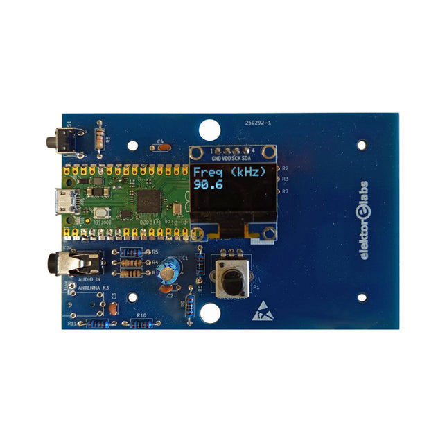
Elektor Labs Elektor AM-Sender-Kit
Bauen Sie Ihren eigenen Vintage-Radiosender Das Elektor AM-Sender-Kit ermöglicht das Streamen von Audio auf Vintage-AM-Radioempfänger. Basierend auf einem Raspberry Pi Pico Mikrocontroller-Modul kann der AM-Sender auf 32 Frequenzen im AM-Band senden, von 500 kHz bis 1,6 MHz in 32 Schritten von ca. 35 kHz. Die Frequenz wird mit einem Potentiometer gewählt und auf einem 0,96" OLED-Display angezeigt. Eine Taste ermöglicht das Umschalten des Sendemodus zwischen Ein und Aus. Die Reichweite des Senders hängt von der Antenne ab. Die integrierte Antenne bietet eine Reichweite von wenigen Zentimetern, sodass der AM-Sender nahe am Radio oder im Radio selbst platziert werden muss. Eine externe Loop-Antenne (nicht enthalten) kann angeschlossen werden, um die Reichweite zu erhöhen. Das Elektor AM-Sender-Kit wird als Bausatz geliefert, den Sie selbst auf die Platine löten müssen. Features Die Platine ist kompatibel mit einem Hammond-1593N-Gehäuse (nicht enthalten).Ein 5-VDC-Netzteil mit Micro-USB-Anschluss (z. B. ein altes Handy-Ladegerät) wird benötigt, um das Kit zu betreiben (nicht enthalten). Stromaufnahme: 100 mA. Die Arduino-Software (benötigt Earle Philhowers RP2040-Boards-Paket) für das Elektor-AM-Sender-Kit sowie weitere Informationen sind auf der Elektor-Labs-Seite dieses Projekts verfügbar. Stückliste Widerstände R1, R4 = 100 Ω R2, R3, R8 = 10 kΩ R5, R6, R9, R10, R11 = 1 kΩ R7 = optional (nicht enthalten) P1 = Potentiometer 100 kΩ, linear Kondensatoren C1 = 22 µF 16V C2, C4 = 10 nF C3 = 150 pF Sonstiges K1 = 4×1 Stiftleiste K2, K3 = 3,5-mm-Buchse Raspberry Pi Pico Drucktaste, Winkelmontage 0,96" monochromes I²C-OLED-Display Leiterplatte 150292-1
€ 34,95€ 29,95
Bestpreis
-

Elektor Digital Linux PC-based Measurement Electronics (E-book)
This book is intended as a highly-practical guide for Hobbyists, Engineers and Scientists wishing to build measurement and control systems to be controlled by a local or remote Personal Computer running the Linux operating system. Both hardware and software aspects of designing typical embedded systems are covered in detail with schematics, code listings and full descriptions. Numerous examples have been designed to show clearly how straightforward it can be to create the interfaces between digital and analog electronics, with programming techniques for creating control software for both local and remote systems. Hardware developers will appreciate the variety of circuits, including a novel, low cost modulated wireless link and will discover how using Matlab® overcomes the need for specialist programming skills. Software developers will appreciate how a better understanding of circuits plus the freedom offered by Linux to directly control at the register level enables them to optimize related programs. There is no need to buy special equipment or expensive software tools in order to create embedded projects covered in this book. You can build such quality systems quickly using popular low-cost electronic components and free distributed or low-cost software tools. Some knowledge of basic electronics plus the very basics of C programming only is required. Many projects in this book are developed using Matlab® being a very popular worldwide computational tool for research in engineering and science. The book provides a detailed description of how to combine the power of Matlab® with practical electronics. With an emphasis on learning by doing, readers are encouraged by examples to program with ease; the book provides clear guidelines as to the appropriate programming techniques “on the fly”. Complete and well-documented source code is provided for all projects. If you want to learn how to quickly build Linux-based applications able to collect, process and display data on a PC from various analog and digital sensors, how to control circuitry attached to a computer, then even how to pass data via a network or control your embedded system wirelessly and more – then this is the book for you! Features of this Book Use the power, flexibility and control offered only by a Linux operating system on a PC. Use a free, distributed downloadable GNU C compiler Use (optional) a low-cost Student Version of Matlab®. Use low-cost electronic sub-assemblies for projects. Improve your skills in electronics, programming, networking and wireless design. A full chapter is dedicated to controlling your sound card for audio input and output purposes. Program sound using OSS and ALSA. Learn how to combine electronic circuits, software, networks and wireless technologies in the complete embedded system.
€ 29,95
Mitglieder: € 23,96
-

OWON OWON HDS2202s 2-Kanal Oszilloskop (200 MHz) + Multimeter + Signalgenerator
Der OWON HDS2202s ist ein tragbarer 3-in-1-Multifunktionstester, der als 2-Kanal-Oszilloskop mit einer Bandbreite von 200 MHz, Multimeter und Signalgenerator verwendet werden kann. Es verfügt über ein kontrastreiches 3,5-Zoll-Farbdisplay, das sich für die Wartung von Außenanlagen, schnelle Messungen vor Ort, die Wartung von Kraftfahrzeugen und die Stromerkennung eignet. usw.Funktionen Oszilloskop + Multimeter + Wellenformgenerator, Multifunktion in einem 3,5 Zoll hochauflösendes, kontrastreiches Farb-LCD-Display, geeignet für den Außenbereich 18650-Lithiumbatterie, kann 3–6 Stunden lang ununterbrochen arbeiten USB-Typ-C-Schnittstelle, unterstützt Powerbank, unterstützt PC-Software-Verbindung Selbstkalibrierungsfunktion SCPI unterstützt, erleichtert die sekundäre Entwicklung Technische Daten Bandwidth 100 MHz Channels 2-ch Oscilloscope + 1-ch Generator Sample Rate 1 GSa/s Acquisition Model Normal, Peak detect Record Length 8K Display 3.5-inch LCD Waveform Refresh Rate 10,000 wfrms/s Input Coupling DC, AC, and Ground Input Impedance 1 MΩ ±2%, in parallel with 16pF ±10pF Probe Attenuation Factors 1X,10X,100X,1000X,10000X Max. input Voltage 400 V (DC+AC, PK-PK, 1MΩ input impedance) (10:1 probe attenuation) Bandwidth Limit (typical) 20 MHz Horizontal Scale 2ns/div - 1000s/div, step by 1 - 2 - 5 Vertical Sensitivity 10mV/div - 10V/div Vertical Resolution 8 bits Trigger Type Edge Trigger Modes Auto, Normal, single Automatic Measurement Frequency, Period, Amplitude, Max, Min, Mean, PK-PK Cursor Measurement ΔV, ΔT, ΔT&ΔV between cursors Communication Interface USB Type-C Multimeter Specifications Max. Resolution 20,000 counts Testing Mode Voltage, Current, Resistance, Capacitance, Diode, and Continuity test Input Impedance 10 MΩ Max Input Voltage AC 750 V, DC 1000 V Max Input Current DC: 10 A, AC: 10 A Diode 0-2 V Waveform Generator Specifications Frequency Output Sine 0.1 Hz - 25 MHz Square 0.1 Hz - 5MHz Ramp 0.1 Hz - 1 MHz Pulse 0.1 Hz - 5 MHz Arbitrary 0.1 Hz - 5 MHz Sampling Rate 125 MSa/s Channel 1-ch Amplitude Range (high impedance) 20 mVpp - 5 Vpp Waveform Length 8K Vertical Resolution 14 bits Output Impedance 50Ω Lieferumfang 1x OWON HDS2202s 1x Netzteil 1x USB-Kabel 1x Passive Sonden 2x Krokodilklemmenkabel 1x Satz Multimeter-Sonden (eine rote und eine schwarze) 1x Manual 1x Sondenkorrektur-Einstellmesser Downloads User Manual Specifications SCPI Protocol Quick Guide Software
€ 238,00


-

, von Clemens Valens FNIRSI SG-003A Signalgenerator
Der multifunktionale Signalgenerator FNIRSI SG-003A ist eine Art Prozessmessgerät zur Erzeugung und Messung von Spannungen, Strömen und Frequenzen, das mit SPS und anderen (industriellen) Prozesssteuerungssystemen...
